

Page 1

LIBRETTO ISTRUZIONI
Italiano English Deutsch Français
INSTRUCTIONS BOOKLET
BEDIENUNGSSANLEITUNG
LIVRET D’INSTRUCTIONS
Cod. 110030298 (ECLISSE)
Ed. 2014
Page 2

Gentile Signora/Signore, congratulazioni!
Lei ha acquistato una cappa di prestigio e di sicura qualità. Perché Lei possa ottenere
le migliori prestazioni, Le suggeriamo di seguire con attenzione le istruzioni per l’uso e
manutenzione che troverà in questo libretto; inoltre, per ordinare i filtri di ricambio al carbone
attivo utilizzi l’apposito tagliando che troverà allegato alla copertina.
Dear Sir/Madam, congratulations!
You have purchased a prestigious range hood of guaranteed quality. For best results, we
suggest that you carefully follow the operating and maintenance instructions provided in this
booklet; in addition, to order spare charcoal filters, use the special coupon on the cover.
Verehrte Kundin, verehrter Kunde
Kompliment! Sie haben eine qualitativ hochwertige Dunstabzugshaube erworben. Um ihre
Leistungsfähigkeit optimal nutzen zu können, sollten Sie die beiliegende Gebrauchs- und
Wartungsanleitung sorgfältig durchlesen und befolgen. Für die Bestellung der ErsatzAktivkohlefilter verwenden Sie bitte den Coupon, der dem Deckblatt beiliegt.
Chère Madame/Cher Monsieur, félicitations!
Vous venez d’acheter une hotte haut de gamme. Pour en tirer les performances les meilleures
veuillez lire avec attention le mode d’emploi et la maintenance que vous trouvez dans ce
manuel ; pour commander les filtres de rechange au carbone actif veuillez vous servir du
coupon annexé à la couverture.
Page 3
600
90
228
1250
472
246
1202
min 10/max 25
180
200
220
407
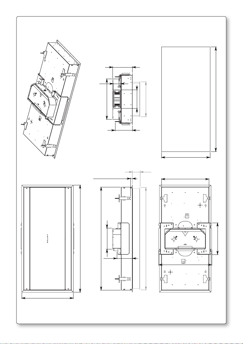
DIMENSIONE FORATURA / HOLE SIZES: 1218x565
565
90
552
1195
617
1218
370
1
Page 4
600
376
1250
275
275
1202
273
200
min 10/max 25
150
407
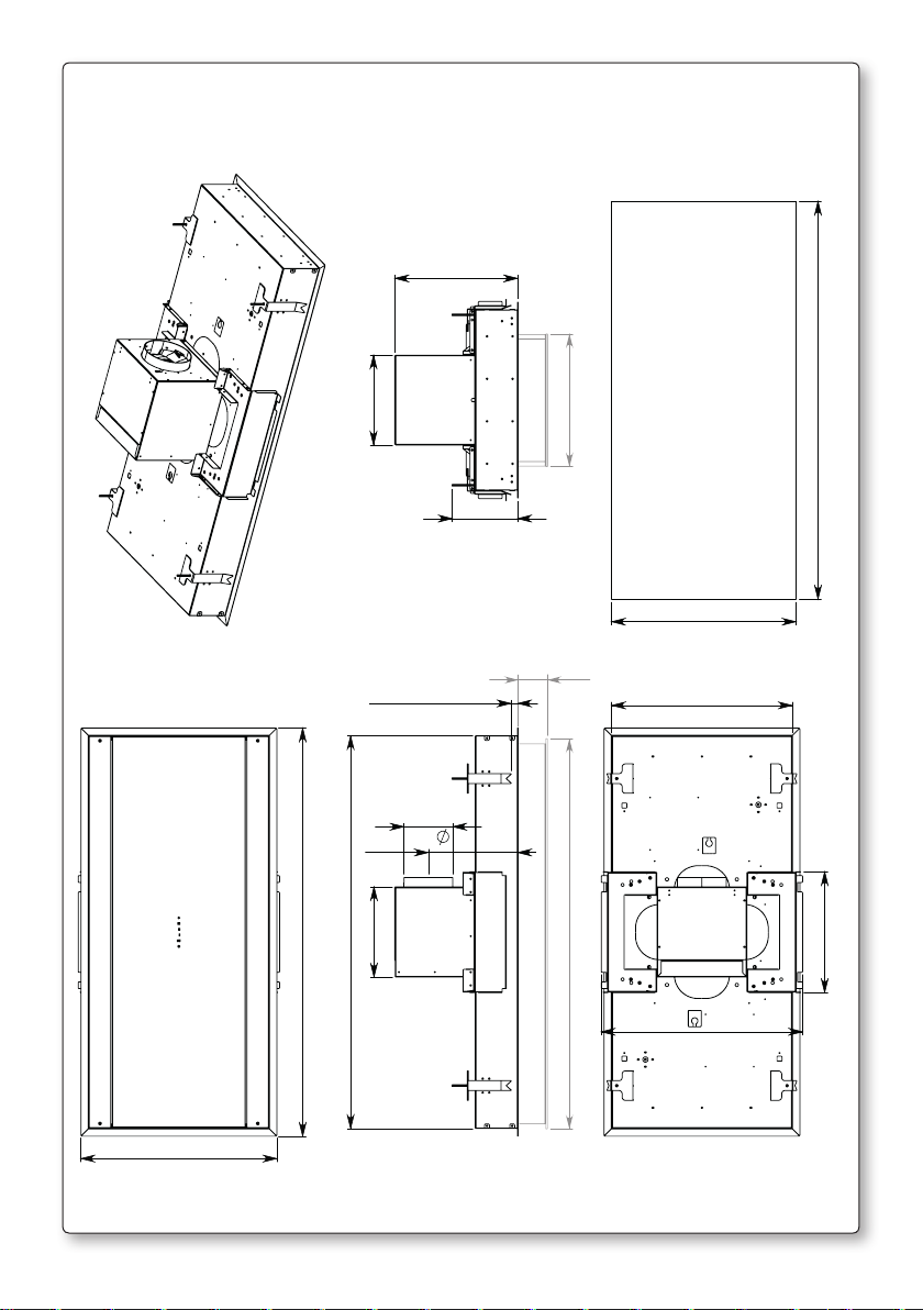
DIMENSIONE FORATURA / HOLE SIZES: 1218x565
1218
565
90
552
1195
370
617
2
Page 5
600
130
1250
150
1202
407
200
90
min 10/max 25
1195
1218
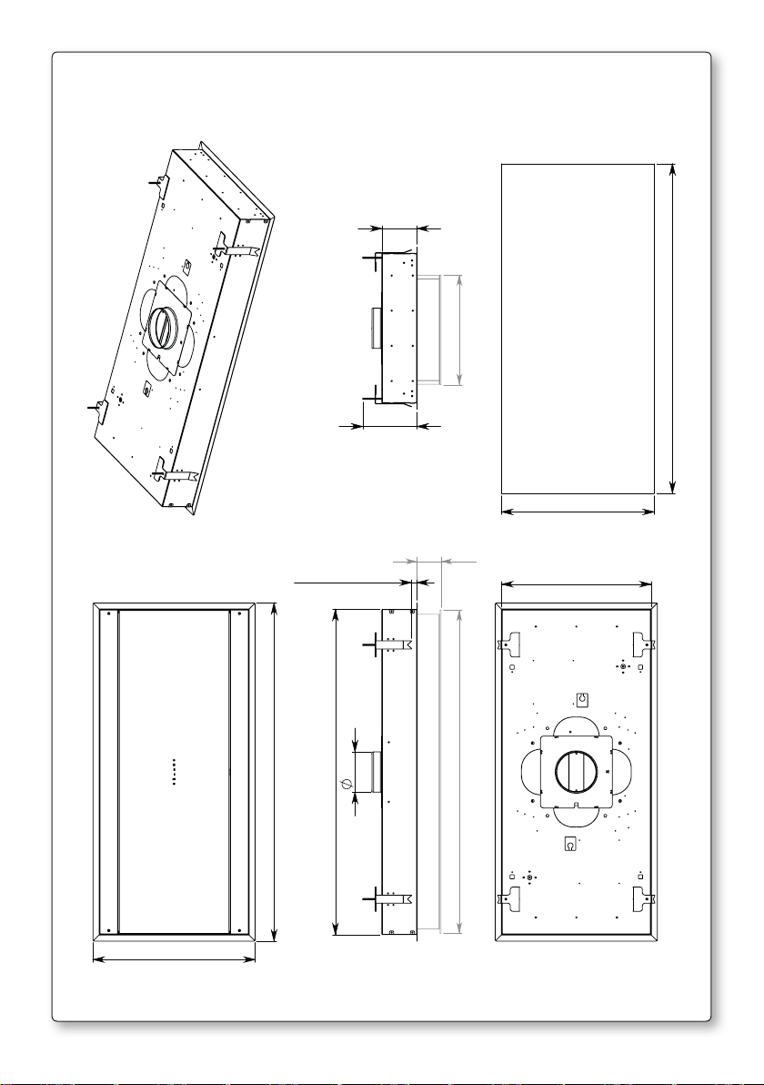
DIMENSIONE FORATURA / HOLE SIZES: 1218x565
565
552
3
Page 6
1A
V1
P
1B
V1
V1
P
V
2
V1
G
V2
V1
4
V2
1
V2
FC
5
V2
UM
V2
FM
4
Page 7
2
A
FL
UM
AIR
B
3
FL
360°
AIR
UM
UM
x8
5
Page 8
4
FALSE CEILING
CONTROSOFFITTO
A
rinforzo controsotto
false ceiling reinforcement
5
Smontaggio / Disassembly
B
UM
G
FALSE CEILING
CONTROSOFFITTO
Montaggio / Assembly
B
B
C
A
G
B
C
6
Page 9
6
FR (optional)
360°
UM
7
FC
UM
7
Page 10
g. 8
A
B
TC SLIM
2
AIR
1
TC SLIM
AIR
2
1
8
Page 11

g. 9
UM SLIM
A
UM SLIM
B
AIR
AIR
SM SLIM
SM SLIM
9
Page 12
g. 10
FALSE CEILING
CONTROSOFFITTO
FALSE CEILING
CONTROSOFFITTO
controsotto
false ceiling
rinforzo controsotto
false ceiling reinforcement
biadesivo
double adhesive
sotto
ceiling
sotto
ceiling
rinforzo controsotto
false ceiling reinforcement
controsotto
false ceiling
10
Page 13
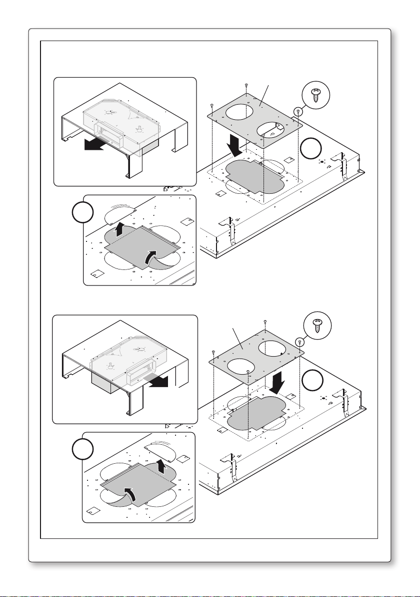
g. 11
g. 12 g. 13
CM
CE
CM
CE
g. 14 g. 15
G
MFL
P
P
11
Page 14

12
Page 15
I
LIBRETTO ISTRUZIONI
A
Se l’apparecchio dovesse essere venduto o trasferito ad un’altra persona, assicurarsi
Queste avvertenze sono state redatte per la vostra sicurezza e per quella degli altri,
Non collegare l’apparecchio a condotti di scarico dei fumi prodotti dalla combustione (caldaie,
Non fare cotture a fiamma “libera” sotto la cappa. Controllare le friggitrici durante l’uso: I’olio
AVVERTENZE
È molto importante che questo libretto istruzioni sia conservato insieme all’apparec-
chiatura per qualsiasi futura consultazione.
che il libretto venga fornito assieme, in modo che il nuovo utente possa essere messo
al corrente del funzionamento della cappa e delle avvertenze relative.
Vi preghiamo, dunque, di volerlo leggere attentamente prima d’installare e di utilizzare l’apparecchio.
Il presente dispositivo non è stato progettato per essere utilizzato da persone (bambini inclusi)
con ridotte capacità fisiche, sensoriali o mentali, o prive di esperienza o conoscenze adeguate,
a meno che non agiscano sotto la supervisione di una persona responsabile della sicurezza o
abbiano ricevuto istruzioni relativamente all’uso del dispositivo.
Occorre sorvegliare i bambini affinché non giochino con il dispositivo.
Il lavoro di installazione deve essere eseguito, da installatori competenti e qualificati, secondo
le norme in vigore.
Se il cavo di alimentazione è danneggiato, esso deve essere sostituito dal costruttore o dal
suo servizio assistenza tecnica o comunque da una persona con qualifica similare, in modo da
prevenire ogni rischio.
Ogni eventuale modifica che si rendesse necessaria all’impianto elettrico per installare la cappa
dovrà essere eseguita solo da persone competenti.
È pericoloso modificare o tentare di modificare le caratteristiche di questo impianto. In caso di
riparazioni o mal funzionamento dell’apparecchio, non tentare di risolvere da soli il problema.
Le riparazioni effettuate da persone non competenti possono provocare danni.
Per eventuali interventi rivolgersi ad un Centro Assistenza Tecnica autorizzato ad eseguire parti
di ricambio.
Controllare sempre che tutte le parti elettriche, (luci, aspiratore), siano spente quando l’apparecchio non viene usato. Leggere tutto il libretto istruzioni prima di effettuare operazioni sulla
cappa.
L’utilizzo della cappa non può essere diverso da quello di aspiratori di fumi di cottura
su cucine domestiche.
Qualsiasi utilizzo diverso da questo solleva il costruttore da qualsiasi responsabilità.
Il peso massimo complessivo di eventuali oggetti posizionatio appesi (ove previsto)
sulla cappa non deve superare 1,5 Kg.
Dopo l’installazione delle cappe in acciaio inox bisogna eseguire la pulizia della stessa per rimuovere i residui di collante protettivo e le eventuali macchie di grasso o oli.
Per questa operazione il costruttore raccomanda l’utilizzo delle salviette in dotazione, disponibili anche in acquisto.
L’utilizzo di altre tipologie di detergenti solleva il costruttore dalla responsabilità sui
danni che ne potrebbero derivare.
L’impianto elettrico è munito di collegamento a terra secondo le norme di sicurezza internazio-
nali; è inoltre conforme alle normative Europee sull’antidisturbo radio.
caminetti,ecc). Verificare che la tensione di rete corrisponda a quella riportata dalla targhetta
posta all’interno della cappa.
surriscaldato potrebbe infiammarsi.
Italiano
13
Page 16
- Assicurarsi che vi sia una adeguata ventilazione nella stanza se la cappa è utilizzata con altri
apparecchi che utilizzano combustibili come gas o altro.
- Non accendere fiamme libere sotto la cappa.
- Non collegare l’apparecchio a condotti di scarico dei fumi prodotti dalla combustione (caldaie, caminetti, ecc).
- Assicurarsi che tutte le normative vigenti sullo scarico dell’aria all’esterno del locale siano
rispettate prima dell’utilizzo della cappa.
Prima di procedere a qualsiasi operazione di pulizia o di manutenzione, disinserire
l’apparecchio togliendo la spina o agendo sull’interruttore generale. La casa costruttrice declina ogni responsabilità per eventuali danni che possano, direttamente o
indirettamente, essere causati a persone, cose ed animali domestici in conseguenza
alla mancanza di tutte le prescrizioni indicate nell’apposito libretto istruzioni e concernenti, specialmente, le avvertenze in tema di installazione, uso e manutenzione
dell’apparecchio.
ATTENZIONE: parti accessibili possono essere calde quando usate con apparecchi di
- Rischio di incendio se la pulizia non è condotta secondo le istruzioni del presente libretto.
cottura.
- Avvertenza: l’installazione delle viti o dei dispositivi di fissaggio non conforme alle presenti
istruzioni può comportare rischi di natura elettrica.
AVVISO:
Il presente prodotto deve essere smaltito al termine della sua vita utile conformemente alle normative in vigore.
B
C
D
CARATTERISTICHE TECNICHE
I dati tecnici dell’elettrodomestico sono riportati su delle targhette, posizionate all’interno della
cappa.
INSTALLAZIONE
(parte riservata solo a persone qualificate per il montaggio della cappa)
La distanza, fra piano cottura e parte inferiore della cappa, consigliata per l’installazione è di circa 110 cm. In casi limiti, perdendo un po’ di efficienza, la distanza può essere incrementata a circa 150 cm. La distanza minima non può essere inferiore a 65 cm come previsto dalla normativa.
Se le istruzioni del piano di cottura a gas specificano una distanza maggiore, bisogna tenerne
conto.
Nella versione aspirante il tubo di uscita dei fumi deve avere un diametro non inferire a quello
del raccordo della cappa.
Nei tratti orizzontali il tubo deve avere una leggera inclinazione (10% circa) verso l’alto per
convogliare l’aria all’esterno dell’ambiente.
Ridurre al minimo le curve, verificare che i tubi abbiano una lunghezza minima indispensabile.
Rispettare le norme vigenti sullo scarico dell’aria all’esterno.
In caso di utilizzo contemporaneo di altre utenze (caldaie, stufe, caminetti, ecc.) alimentate a
gas o con altri combustibili, provvedere ad una adeguata ventilazione del locale in cui avviene
l’aspirazione dei fumi, secondo le norme vigenti.
Istruzioni di montaggio: vedi sez. “O” del presente manuale.
ALLACCIAMENTO ELETTRICO
(parte riservata solo a persone qualificate per l’allacciamento)
ATTENZIONE!
Prima di effettuare qualsiasi operazione all’interno della cappa scollegare l’apparec-
14
Page 17

chio dalla rete elettrica.
Assicurarsi che non vengano scollegati o tagliati fili elettrici all’interno della cappa;
nel caso si verifichino tali situazioni contattare il centro assistenza più vicino. Per
l’allacciamento elettrico rivolgersi a personale qualificato.
Il collegamento deve essere eseguito in conformità con le disposizioni di legge in vigore. Controllare che la valvola limitatrice e l’impianto elettrico possano sopportare il carico dell’apparecchio (vedere targhetta caratteristiche tecniche al punto B). Alcuni tipi di apparecchi possono
essere dotati di cavo senza spina; in questo caso, la spina da utilizzare deve essere dei tipo
“normalizzato” tenendo conto che:
- il filo giallo-verde deve essere utilizzato per la messa a terra,
- il filo blu deve essere utilizzato per il neutro,
- il filo marrone deve essere utilizzato per la fase, il cavo non deve entrare in contatto con parti
calde aventi temperature superiori a 70°C.
- montare sul cavo di alimentazione una spina adatta al carico e collegarla ad una adeguata
spina di sicurezza.
Se un apparecchio fisso non è provvisto di cavo di alimentazione e di spina, o di altro dispositivo che assicuri la disconnessione dalla rete, con una distanza di apertura dei contatti che
consenta la disconnessione completa nelle condizioni della categoria di sovratensione III, le
istruzioni devono indicare che tali dispositivi di disconnessione devono essere previsti nella
rete di alimentazione conformemente alle regole di installazione.
Il cavo di terra giallo/verde non deve essere interrotto dall’interruttore.
Prima di collegare l’apparecchio alla rete elettrica, controllare che:
- la tensione d’alimentazione corrisponda a quella indicata dalla targhetta caratteristiche tec-
niche.
- la presa di terra sia corretta e funzionale.
- l’impianto di alimentazione sia munito di efficace collegamento di terra secondo le norme
vigenti.
- la presa o l’interruttore omnipolare usati siano facilmente raggiungibili con l’apparecchiatura
installata.
La casa costruttrice declina ogni responsabilità nel caso le norme di sicurezza non
vengano rispettate.
Italiano
E
CAPPA IN VERSIONE
AD EVACUAZIONE ESTERNA (aspirante)
In questa versione i fumi e i vapori della cucina vengono convogliati verso l’esterno attraverso
un tubo di scarico.
Il convogliatore di scarico che sporge sulla parte superiore della cappa deve essere collegato
con un tubo che conduce i fumi e i vapori in una uscita esterna. In questa versione vanno tolti i
filtri al carbone attivo se esistenti; per l’estrazione vedere istruzioni al punto F. Quando la cappa
da cucina viene utilizzata contemporaneamente ad altri apparecchi che impiegano gas o altri
combustibili, il locale deve disporre di sufficiente ventilazione secondo le norme vigenti.
Deviazione per la Germania:
Quando la cappa da cucina e apparecchi alimentati con energia diversa da quella elettrica
sono in funzione simultaneamente, la pressione negativa nel locale non deve superare i 4 Pa
(4 x 10⁻⁵ bar).
F
Cappa non predisposta per filtro carbone.
CAPPA IN VERSIONE A RICICLO INTERNO (filtrante)
15
Page 18

G
FUNZIONAMENTO CONTROLLO ELETTRONICO
TASTO 1
Timer:
Con il motore in funzione la pressione del tasto attiva lo spegnimento temporizzato del motore
dopo 15 minuti. Il tasto 1 lampeggia ad indicare che la funzione è attiva. Al termine dei 15 minuti
il motore e la luce si spengono.
Variando la velocità del motore non si interrompe il conteggio. Se il motore viene fermato con
il tasto 2 la funzione si disinserisce automaticamente. Quando la funzione timer è attiva, è possibile disinserirla premendo il tasto 1.
Apertura dell’elemento mobile (modalità assistenza):
Quando tutti i led della tastiera sono spenti (luce e motore off) la pressione prolungata del tasto
consente di abbassare l’elemento mobile della cappa per poter effettuare la manutenzione.
Durante questo stato non è possibile azionare il motore, i tasti T2..T5 sono inibiti.
Chiusura dell’elemento mobile (modalità assistenza):
Per ottenere la chiusura dell’elemento mobile in modalità assistenza (anta aperta e motore spento) effettuare una pressione prolungata del tasto1. Da questo momento i tasti T2..T5 riprendono
a funzionare.
TASTO 2
1°/OFF:
Se il motore è fermo, la pressione del tasto abbassa l’elemento mobile ed attiva il motore alla 1°
velocità: questo avviene dopo 20 secondi a partire da quando la parte mobile inizia l’apertura
(il tasto T2 si illumina). Se il motore è alla 1° velocità, la pressione del tasto ferma il motore e il
led del tasto T2 si spegne.Se il motore è ad una velocità diversa dalla 1°, la pressione del tasto
aziona la 1° velocità.
Funzione Ricircolo:
A motore spento la pressione prolungata del tasto T2 attiva la funzione ricircolo; il tasto T2
lampeggia. Durante la funzione ricircolo (della durata di 24 ore), la cappa effettua un ciclo di
funzionamento che prevede l’attivazione del motore alla 1° velocità per 1 ora, seguito da 3 ore
nelle quali il motore è fermo.Tali cicli vengono ripetuti fino al timeout delle 24 ore. L’elemento
mobile rimane sempre abbassato (la 1° velocità si attiva sempre dopo 20 secondi a partire da
quando la parte mobile inizia l’apertura).
Con questa funzione attivata non si possono selezionare le altre velocità. Per togliere questa
funzione, tenere premuto per almeno 3 secondi il tasto T2.
TASTO 3
Se il motore è ad una velocità diversa dalla 2°, la pressione del tasto aziona la 2° velocità, e il tasto
T3 si illumina. Se il motore è fermo, il tasto è disattivato.
TASTO 4
Se il motore è ad una velocità diversa dalla 3°, la pressione del tasto aziona la 3° velocità, e il tasto
T4 si illumina. Se il motore è fermo, il tasto è disattivato.
TASTO 5
Se il motore è ad una velocità diversa dalla 4°, la pressione del tasto aziona la 4° velocità, e il tasto
T5 lampeggia. Se il motore è fermo, il tasto è disattivato.
La 4° velocità è temporizzata; se l’utente seleziona una diversa velocità, il motore rimane in 4°
per 7 minuti e successivamente si posiziona in 3°. Il tasto T5 si spegne e si illumina il tasto T4.
16
Page 19

TASTO 6
Luce:
La pressione breve del tasto T6 accende e spegne la luce.
Associazione del radiocomando alla cappa :
Con motore e luce spenta, la pressione prolungata del tasto T6 attiva la modalità di associazione
del radiocomando.
Il Tasto T6 lampeggia per un massimo di 10 secondi. Durante questo periodo è necessario premere almeno un tasto del radiocomando per effettuare l’associazione. La funzione si disattiva
allo scadere dei 10 secondi o prima nel caso venga viene rilevato un telecomando compatibile.
Funzione Radiocomando:
Tasto Luce: La pressione del tasto Luce accende/spegne la luce
Tasto ‘
‘ : La pressione del tasto decrementa la velocità del motore. Se si è in 1° velocità, la pressione del tasto spegne il motore.
Tasto ‘
‘ : Se il motore è spento, la pressione del tasto attiva il motore alla 1° velocità. Se il motore
è in funzione, la pressione del tasto incrementa la velocità fino alla velocità massima.
Tasto Timer: Se il motore è attivo, la pressione del tasto timer attiva/disattiva la funzione timer
Cambio Codice trasmissione radiocomando (solo in caso di più cappe posizionate
vicine tra loro e che necessitano di funzionare in modo indipendente)
Premere il tasto “Luce” insieme al tasto “Timer” del radiocomando fino a che il led blu non inizia
a lampeggiare lentamente. Se entro 5 secondi si preme il tasto “-” del radiocomando viene
generato e memorizzato il nuovo codice. La memorizzazione viene confermata da 3 lampeggi
brevi del led.
Ogni volta che viene generato un nuovo codice o impostato il codice di default nel radiocomando,
bisogna eseguire anche la procedura “Associazione del radiocomando alla cappa” (Tasto Luce
della pulsantiera) descritta precedentemente.
Per ritornare al codice di default bisogna premere il tasto “-” insieme al tasto “+” del radiocomando per più di 5 secondi. La memorizzazione del codice di default viene segnalata con 3 brevi
lampeggi del led.
Italiano
H
FILTRI METALLICI E FILTRI CARBONE
1. FILTRI METALLICI
Per accedere ai filtri metallici deve essere abbassata la parte mobile in modalità assistenza
(descritta precedentemente) attenendosi alla seguente procedura: quando tutti i led della
tastiera sono spenti (luce e motore off) la pressione prolungata del tasto consente di
abbassare l’elemento mobile della cappa per poter effettuare la manutenzione. Durante
questo stato non è possibile azionare il motore, i tasti T2..T5 sono inibiti. Rimuovere i filtri
metallici fissati con dei magneti alla parte mobile, tirandoli leggermente verso il lato esterno della cappa. Procedere con la pulizia dei filtro metallici come indicato al punto L1 e riposizionarli con cura sulla parte mobile della cappa. Per la chiusura dell’elemento mobile in
modalità assistenza: effettuare una pressione prolungata del tasto1. Da questo momento i
tasti T2..T5 riprendono a funzionare.
2. FILTRI AL CARBONE ATTIVO
Cappa non predisposta per filtro carbone e quindi non installabile in versione a riciclo
interno.
17
Page 20

ILLUMINAZIONE MONTAGGIO E SOSTITUZIONE
I
La cappa è dotata di illuminazione con faretti led ad alta efficienza, basso consumo e durata
molto elevata in condizioni di normale utilizzo.
L
Una costante manutenzione garantisce un buon funzionamento ed un buon rendimento
MANUTENZIONE E PULIZIA
nel tempo. Particolari attenzioni vanno rivolte ai filtri metallici antigrasso ed ai filtri al carbone
attivo, infatti la pulizia frequente dei filtri e dei loro supporti garantisce che sulla cappa non si
accumulino grassi che sono pericolosi per la facilità di incendio.
1. FILTRI ANTIGRASSO METALLICI
Hanno la funzione di trattenere le particelle grasse in sospensione, pertanto si consiglia di
lavarli ogni mese in acqua calda e detersivo evitando di piegarli. Attendere che siano ben
asciutti prima di rimontarli.
Per lo smontaggio e montaggio vedi istruzioni al punto H1. Si raccomanda costante fre-
quenza nell’operazione.
2. FILTRI AL CARBONE ATTIVO
Cappa non predisposta per filtro carbone.
3. PULIZIA ESTERNA
Si raccomanda di pulire le superfici esterne delle cappe almeno ogni 15 giorni per evitare
che le sostanze oleose o grasse possano intaccare le superfici in acciaio.
La pulizia della cappa va eseguita usando un panno umido con detersivo liquido neutro o
con alcool denaturato.
Nel caso di materiale con trattamento antimpronta (Fasteel) eseguire la pulizia solo con
acqua e sapone neutro utilizzando un panno morbido avendo cura di risciacquare e
asciugare accuratamente. Non si devono utilizzare prodotti contenenti sostanza abrasive,
panni con superfici ruvide o panni comunemente in commercio per la pulizia dell’acciaio.
L’utilizzo di sostanze abrasive e panni ruvidi danneggerà irreparabilmente il trattamento
superficiale dell’acciaio.
Conseguenza diretta del non rispetto di tali avvertenze sarà il deterioramento irreversibile
della superficie dell’acciaio.
Tali avvertenze dovranno essere conservate insieme al libretto istruzioni della cappa. Il
produttore declina ogni responsabilità qualora non vengano rispettate tali istruzioni.
4. PULIZIA INTERNA
É vietata la pulizia di parti elettriche o parti relative al moto re all’interno della cappa, con
liquidi o solventi;
Non usare prodotti contenenti abrasivi.
Effettuare tutte queste operazioni scollegando preven tivamente l’apparecchio dalla
La sua nuova apparecchiatura è coperta da garanzia. Le condizioni di garanzia sono riportate
18
rete elettrica.
M
GARANZIA
per esteso sull’ulti ma pagina di copertina di questo libretto.
La casa costruttrice non risponde delle possibili ine sattezze, imputabili ad errori di stam-
pa o di trascrizio ne, contenute nel presente libretto. Si riserva di appor tare ai propri prodotti quelle modifiche che ritenesse necessarie o utili, anche nell’interesse dell’utenza,
senza pregiudicare le ca ratteristiche essenziali di fun zionalità e di sicurezza.
Page 21

N
ATTENZIONE IL CONTROSOFFITTO DEVE ESSERE OPPORTUNAMENTE RINFORZA
MONTAGGIO CAPPA
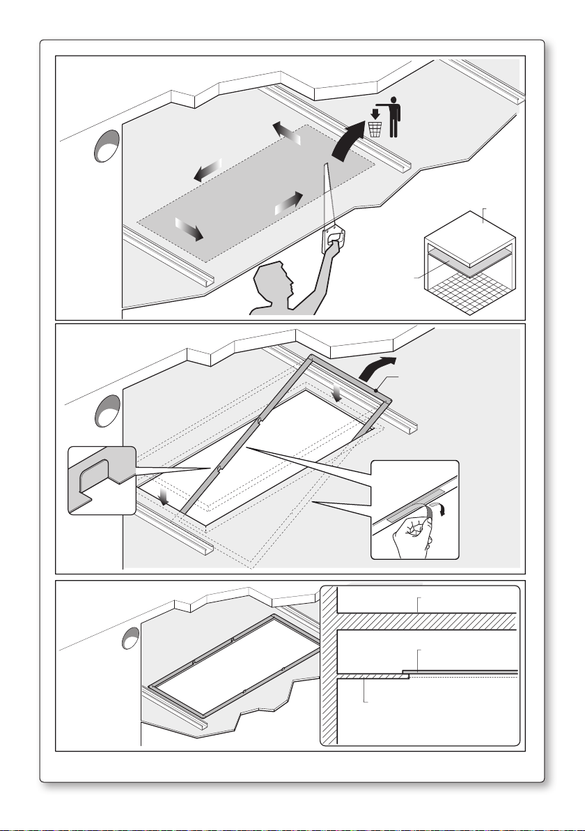
- Predisporre foro sul contro-soffitto secondo le indicazioni dei disegni presenti all’inizio del
libretto. Fissare la dima di ulteriore rinforzo, in dotazione, sulla parte interna non in vista del
controsoffitto come illustrato in figura 10.
TO PER SORREGGERE IN SICUREZZA LA CAPPA.
Nota: in caso di utilizzo della valvola di non ritorno in plastica si suggerisce di montarla sull’uscita del convogliatore nel caso UM sia montata sulla cappa; diversamente, installarla sul raccordo
ricavato nella flangia FC. Per la modalità di montaggio della valvola vedi istruzioni presenti nel
suo imballo.
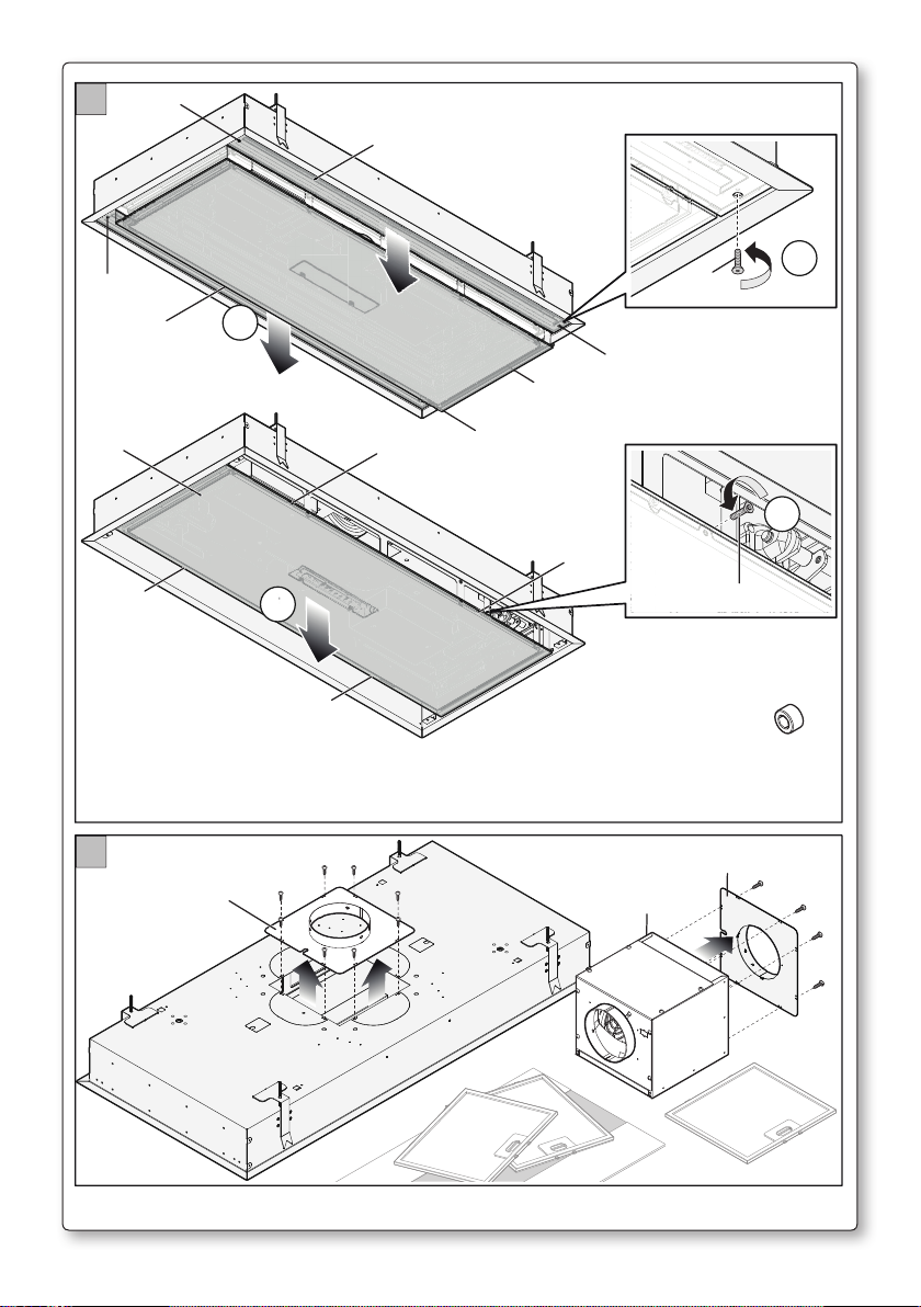
- Rimuovere i pannelli in vetro laterali; ai pannelli sono associate le strip led che fungono da
illuminazione, per cui è necessario scollegare il connettore presente.
- Rimuovere successivamente il vetro centrale (G), vedi fig. 1°; per rimuovere il vetro scollegare
il connettore della pulsantiera elettronica.
In questo modo si ha libero accesso ai fori di fissaggio delle unità motore.
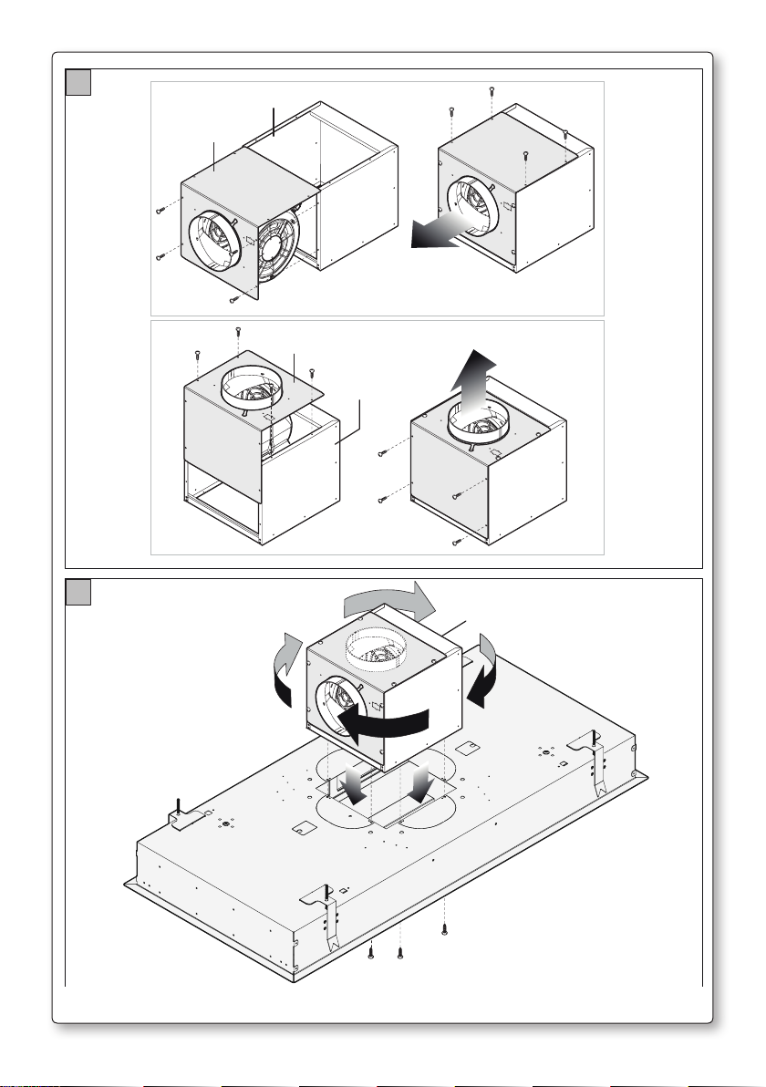
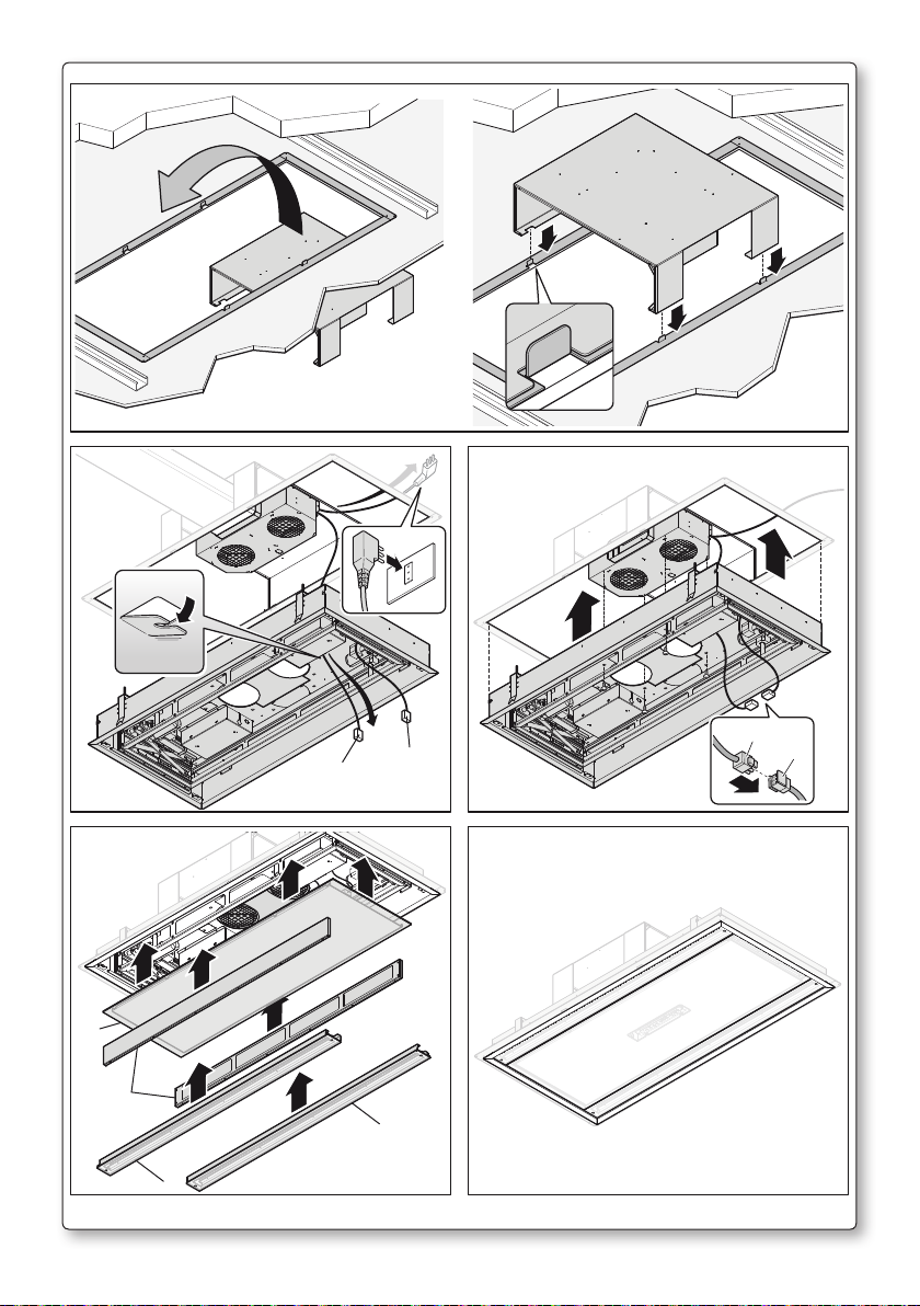
- Individuare il tipo di installazione per la versione aspirante:
Con unità motore (UM) fissata sulla cappa
1) Rimuovere la flangia FC montata sulla cappa e la flangia FM montata sulla UM (fig. 1B).
Definire la direzione di uscita dell’aria mediante la rotazione della flangia FL dell’unità motore
(vedi fig. 2). Fissare UM alla cappa secondo la direzione di uscita dell’aria desiderata (vedi fig. 3).
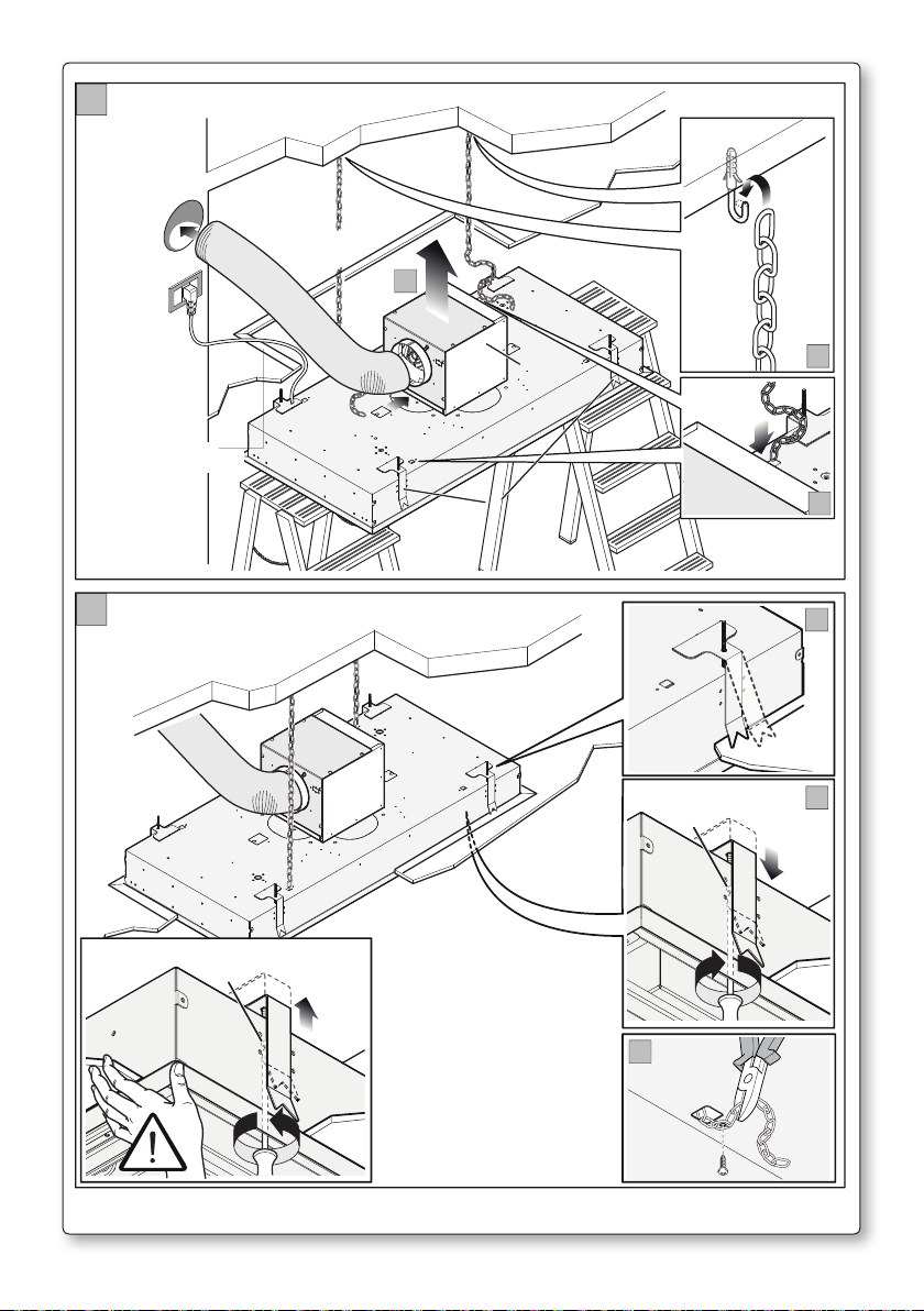
2) Fissare le catenelle di sicurezza al soffitto con le viti e i tasselli in dotazione (vedi fig. 4).
3) Sollevare la cappa in prossimità del contro-soffitto: collegare con tubo flessibile l’uscita del
motore di UM al condotto di scarico esterno dell’aria. Eseguire il collegamento elettrico solo
dopo aver disinserito l’alimentazione elettrica che alimenta la cappa. Infilare le catenelle di
sicurezza sui fori predisposti nella parte superiore della cappa (fig. 5).
4) Inserire la cappa nel contro-soffitto precedentemente rinforzato. I ganci G aprendosi sorreggono provvisoriamente la cappa sul contro-soffitto.
Avvitare (girare in senso orario) tutte le viti (B) in modo da aprire i ganci e bloccare la
cappa sul pannello del contro-soffitto. Per rimuovere la cappa dal contro-soffitto svitare
(girare senso anti-orario) le viti (B) prestando attenzione a sorreggere la cappa adeguatamente
per evitare la caduta della cappa.
Fissare la catenella alla cappa con le viti in dotazione e tagliare la catena in eccesso. Verificare
che la cappa sia ben fissata al contro-soffitto (vedi fig. 5).
5) Rimontare i filtri (MFL) i pannelli in vetro laterali e il vetro centrale, avendo cura di ricollegare
i connettori relativi alle strip led ed alla pulsantiera elettronica, seguendo l’operazione inversa
descritta in fig. 1 A (vedi anche fig. 14).
Italiano
19
Page 22

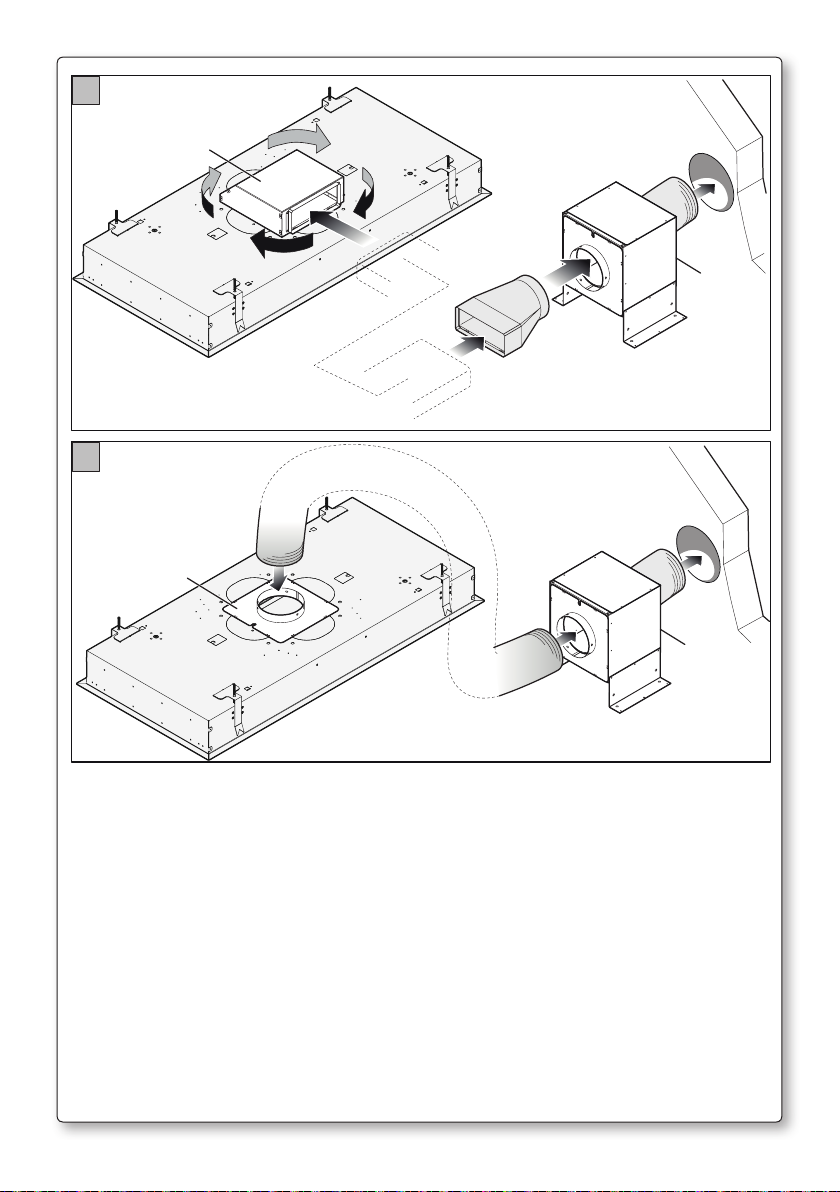
Motore remoto posizionato in un vano tecnico protetto dagli agenti
atmosferici all’interno dell’abitazione
Definire il tipo di uscita:
- Uscita rettangolare da 90x220 mm (fig. 6).
Rimuovere la flangia FC fissata sulla cappa e montare la flangia per tubo rettangolare FR (optio-
nal). Installare UM nella posizione desiderata.
- Uscita circolare diam.150 mm (fig. 7).
Verificare che la flangia FC sia montata sulla cappa. Installare UM nella posizione desiderata.
- Nel caso di installazione con motore remoto collegare il corpo cappa alla terra dell’impianto
elettrico (dopo verifica della sua funzionalità), mediante idoneo cavo. Si raccomanda di rispettare le norme vigenti in materia di sicurezza elettrica degli impianti e degli apparecchi per la
messa a terra degli apparecchi.
- Seguire le istruzioni del paragrafo precedente a partire dal punto 2.
- Rispettare le norme vigenti per lo scarico dell’aria.
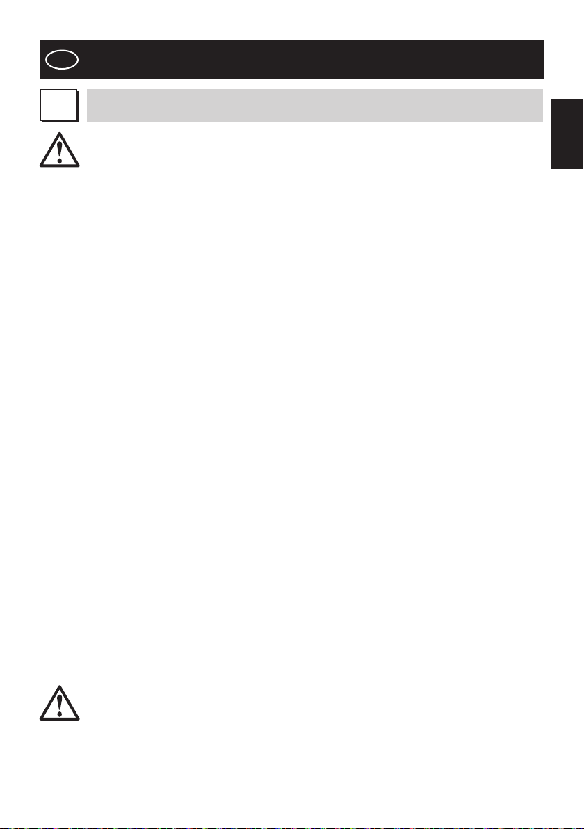
Con unità motore slim (UM SLIM) fissata sulla cappa
1) Definire direzione uscita aria desiderata soluzione A o B.
2) Fissare di conseguenza il tampone (TC SLIM) sulla cappa (vedi fig. 8) e rimuovere semitranciati relativi.
3) Fissare (UM SLIM) sul supporto (SM SLIM) usando le viti in dotazione in base alla direzione di
uscita aria stabilita (vedi fig. 9).
4) Collocare l’assieme (SM SLIM+UM SLIM) sul controsoffitto come illustrato in figura 10-11
(vedi dettaglio per centraggio).
5) Seguire poi le indicazioni montaggio punti 2-3-4 della versione “Montaggio con unità (UM)
fissata sulla cappa”, ricordandosi di far passare il cablaggio con connettore (CM) attraverso l’apposita asola predisposta sulla parte superiore della cappa (fig. 12).
6) Fissare il motore slim (UM SLIM) al corpo cappa mediante le 4 viti in dotazione. Collegare il
connettore (CM) al connettore (CE) dell’elettronica della cappa (fig.13).
7) Rimontare i filtri (MFL) i pannelli in vetro laterali e il vetro centrale, avendo cura di ricollegare
i connettori relativi alle strip led ed alla pulsantiera elettronica, seguendo l’operazione inversa
descritta in fig. 1 A (vedi anche fig. 14).
Alimentare elettricamente la cappa e verificare le relative funzionalità.
20
Page 23

GB
INSTRUCTIONS BOOKLET
A
Do not connect the appliance to flues (from boilers, fireplaces, etc.). Make sure the mains volt-
Never cook on “open” flames under the range hood.
Check deep-fryers during use: superheated oil may be flammable.
WARNINGS
This instruction booklet must be kept together with the appliance for future refer-
ence. If the appliance is sold or consigned to other parties, check that the booklet
is supplied with it, to ensure that the new user has the correct information on the
operation of the range hood and is aware of the warnings. These warnings have been
provided for the your safety and the safety of others. As a result, please read them
carefully before installing and operating the appliance.
This appliance is not intended for use by persons (including children) with reduced physical,
sensory or mental capabilities, or lack of experience and knowledge, unless they have been
given supervision or instruction concerning use of the appliance by a person responsible for
their safety.
Children should be supervised to ensure that they do not play with the appliance.
The appliance must be installed by qualified personnel, in accordance with the standards
in force. If the supply cord is damaged, it must be re-placed by the manufacturer, its service
agent or similarly qualified persons in order to avoid a hazard. Any modifications that may be
required to the electrical system for the installation of the range hood must only be made by
qualified electricians.
It is dangerous to modify or attempt to modify the characteristics of this system. In the event of
malfunctions or if repairs are required to the appliance, do not attempt to solve the problems
directly.
Repairs performed by unqualified persons may cause damage. For all repair and other work on
the appliance, contact an authorised service/spare parts centre.
Always check that all the electrical parts (lights, exhaust device), are off when the appliance is
not being used. Read the entire instruction booklet before performing any operations on the
range hood.
The range hood must only be used for the exhaust of cooking fumes in home kitchens. The manufacturer disclaims all liability for any other use of the appliance. The
maximum weight of any object placed above the hood, or hung to it (if possible)
must not exceed 1,5 kilos. After installing the stainless steel hood, clean it in order
to remove any residue of the protective glue, and stains of grease or oil. The manufacturer recommends its cleaning cloth available for purchase. The manufacturer
accepts no liability in case of damage caused by the use of different detergent types.
The electrical system features an earth connection in compliance with international safety
standards; furthermore, it is compliant with the European standard for electromagnetic compatibility.
age corresponds to the values on the rating plate located inside the range hood.
- Ensure there is adequate ventilation of the room when the rangehood is used at the same
time as appliances burning gas or other fuels.
- Do not flambe under the rangehood
- The exhaust air must not be discharged into a flue which is used for exhausting fumes from
appliances burning gas or other fuels.
- Ensure that all regulations concerning the discharge of exhaust air have been fulfilled before
you use the appliance.
English
21
Page 24

Before performing any cleaning or maintenance operations, disconnect the appli-
ance by unplugging it or using the main switch. The manufacturer disclaims all liability for any damage that may be directly or indirectly caused to people, things and
animals due to the failure to follow all the instructions provided in this booklet and
above all the warnings relating to the installation, operation and maintenance of the
appliance.
CAUTION: Accessible parts may become hot when used with cooking appliances
- there is a fire risk if cleaning is not carried out in accordance with the instructions
Warning: Failure to install the screws or fixing device in accordance with these instructions
may result in electrical hazards
CAUTION:
This product must be disposed of at end of life according to the rules in force.
B
TECHNICAL SPECIFICATIONS
The technical data pertaining to the electric appliance The technical specifications of the appliance are shown on the rating plates located inside the range hood.
C
D
INSTALLATION
(Section reserved for qualified installers of the range hood)
The recommended distance between the cooker and the lower part of the range hood for the
installation is about 110 cm. In borderline cases, with a slight efficiency loss, the distance can be
increased to about 150 cm. The minimum distance cannot be less than 65 cm, as envisioned
by the Standard.
Should the instructions of the gas cooker specify a greater distance, take this into consideration.
In the outside exhaust version, the diameter of the fume discharge duct must be no smaller
than the range hood connection.
In the horizontal sections, the duct must slope slightly (around 10%) upwards, so at to better
convey the air outside of the room.
Reduce curves to the bare minimum, and check that the length of the ducts is also the bare
minimum.
Comply with the current regulations on air discharge into the atmosphere.
If other appliances that use gas or other fuels are being used at the same time (boiler, stove,
fireplaces, etc.), make sure the room where the fumes are extracted is well ventilated, in compliance with the current regulations.
Assembly instructions: see section “O” of the booklet.
ELECTRICAL CONNECTIONS
(Section reserved for qualified installers)
WARNING!
Before doing any work inside the range hood, disconnect the appliance from the
mains power supply.
Check that the wires inside the range hood are not disconnected or cut; if this is the
case, contact your nearest service centre. The electrical connections must be performed by qualified personnel.
The connections must be performed in compliance with the legal standards in force. Check
22
Page 25

that the relief valve and the electrical system are able to support the load of the appliance (see
the technical specifications in point B).
Some types of appliance are supplied with a cable without plug; in this case, “standardised”
plugs must be used, keeping in mind that:
- the yellow-green wire must be used for the earth,
- the blue wire must be used for the neutral,
- the brown wire must be used for the phase; the cable must not come into contact with hot
parts (over 70°C).
- fit a plug that is suitable for the load to the power cable, and connect it to a suitable power
outlet.
For appliances that come supplied with cable and plug please ensure they are plugged into a
circuit suitable for this appliance.
Please refer to a qualifed person. (See technical specifications in point B).
The manufacturer declines all liability if the safety standards are not observed.
English
E
F
G
RANGE HOOD WITH OUTSIDE DISCHARGE
In this version, the fumes and steam from the kitchen are conveyed outside through an exhaust duct.
The exhaust conveyor that protrudes from the upper part of the range hood must be connected to a duct that carries the fumes and steam outside. In this version, the charcoal filters,
if fitted, should be removed; to do this, see the instructions in point F. There must be adequate
ventilation of the room when the range hood is used at the same time as appliances burning
gas or other fuels, according to the standard.
Deviation for Germany:
When the range hood and appliances supplied with energy other than electricity are simultaneously in operation, the negative pressure in the room must not exceed 4 Pa (4x10 E-5 bar).
RECIRCULATING RANGE HOOD (with filter)
Hood not designed for charcoal filters.
ELECTRONIC CONTROL FUNCTIONING
(exhaust)
KEY 1
Timer:
When the motor is running, pressing this key will activate the timer for the motor to shut-down
after 15 minutes. Key 1 flashes to indicate that the function is active. The motor and light switch
off after 15 minutes.
The countdown does not stop if the motor speed is changed. If the motor is stopped with
key 2, the function will automatically deactivate. When the timer function is active, it can be
deactivated by pressing key 1.
Opening the mobile part (assistance mode):
When all the LEDs on the keyboard are switched off (light and motor off), pressing and holding
the key will allow you to open the mobile part of the range hood for maintenance operations.
In this state, the motor cannot be activated. Keys T2..T5 are inhibited.
Closing the mobile part (assistance mode):
To close the mobile part in assistance mode (door open and motor off) press and hold key 1.
Keys T2..T5 will start working again.
23
Page 26

KEY 2
1°/OFF:
If the motor is stopped, pressing the key lowers the mobile part and activates the motor at the
1st speed: this takes place 20 seconds after the mobile part starts opening (key T2 lights up).
If the motor is at the 1st speed, pressing the key makes the motor stop and the LED for key
T2 switches off. If the motor is at a speed other than the 1st speed, pressing the key activates
the 1st speed.
Recirculation Function:
When the motor is switched off, pressing and holding key T2 activates the recirculation function; key T2 flashes. During the recirculation function (that lasts 24 hours), the hood runs an
operating cycle that involves the activation of the motor at the 1st speed for 1 hour, followed
by 3 hours during which the motor is idle. These cycles are repeated until the 24 hours have
elapsed. The mobile part always remains lowered (the 1st speed is activated 20 seconds after
the mobile part starts opening).
With this feature enabled, you cannot select other speeds. To deactivate this function, keep the
T2 key pressed for at least 3 seconds.
KEY 3
If the motor is at a speed other than the 2nd speed, pressing the key activates the 2nd speed
and key T3 lights up. If the motor is stopped, the key is disabled.
KEY 4
If the motor is at a speed other than the 3rd speed, pressing the key activates the 3rd speed
and key T4 lights up. If the motor is stopped, the key is disabled.
KEY 5
If the motor is at a speed other than the 4th speed, pressing the key activates the 4th speed
and key T5 lights up. If the motor is stopped, the key is disabled.
The 4th speed is timed; if the user selects another speed, the motor will stay at the 4th speed
for 7 minutes and will then switch to the 3rd speed. The T5 key will switch off and the T4 key
will light up.
KEY 6
Light:
By briefly pressing key T6, you can turn the light on and off.
Associating the radio control with the hood:
Pressing and holding key T6 with the motor and light off activates the radio control association
mode. Key T6 will flash for a maximum of 10 seconds. During this period, press at least one key
on the radio control to associate the device. The function will be disabled after 10 seconds have
elapsed, or earlier in the event that a compatible remote control is detected.
Radio control
Place the device away from sources of electromagnetic waves which could interfere with the
radio control and consequently with the hood electronics. The maximum operating distance
is 3 metres; the distance may vary according to the presence of electromagnetic interference
from other devices.
Radio control function:
Light Key: Pressing the Light key will switch the light on/off
24
Page 27

‘ ‘ key: Pressing the key will decrease motor speed. If the 1st speed is active, pressing the key
switches the motor off.
‘
‘ key: If the motor is turned off, pressing the key activates the motor at the 1st speed. If the
motor is running, pressing the key increases the motor speed to the maximum speed.
Timer key: If the motor is active, pressing the timer key activates/deactivates the timer function
Changing the radio control transmission code (only in the event that there are several hoods close to each other and they need to operate independently)
Press the Light key together with the radio control Timer key until the blue LED starts
flashing slowly. If the “-” key on the radio control is pressed within 5 seconds, the new code will
be generated and saved. Saving is confirmed by 3 short flashes of the LED.
Every time a new code is generated or the radio control default code is set,
you must carry out the “Associating the radio control with the hood” procedure (pushbutton
panel Light key) described above.
To return to the default code, press the “-” and “+” keys together for over 5 seconds. Successfully
saving the default code will be signalled by 3 short flashes of the LED.
English
H
METALLIC FILTERS AND CARBON FILTER
1 METAL FILTERS
In order to access the metal filters, the mobile part must be lowered in assistance mode (described above) by following this procedure: when all the LEDs on the keyboard are switched
off (light and motor off) pressing and holding the key allows the mobile part of the hood to be
lowered for maintenance. In this state, the motor cannot be activated. Keys T2..T5 are inhibited.
Remove the metal filters fastened with magnets to the mobile part, pulling them gently towards the outside of the hood.
Clean the metal filters as described in section L1 and put them back in place carefully on the
mobile part of the hood.
To close the mobile part in assistance mode: press and hold key 1. Keys T2..T5 will start working again.
2. ACTIVATED CARBON FILTERS
Hood not suitable for a carbon filter and therefore the internal recirculation version cannot be
installed.
LIGHTING ASSEMBLY AND REPLACEMENT
I
The range hood is equipped with high efficiency, low consumption LED spotlights with ex-
Constant maintenance ensures the correct operation and efficiency of the appliance over time.
tremely long duration under normal use conditions.
L
MAINTENANCE AND CLEANING
Special attention should be paid to the metal grease-trapping filters and the charcoal filters.
Frequent cleaning of the filters and their supports will ensure that fats and grease do not accumulate on the range hood, with the consequent risk of fire.
1. METAL GREASE-TRAPPING FILTERS
These trap the fat and grease particles suspended in the air, and therefore should be
washed every month in hot water and detergent, without bending them. Wait until they
25
Page 28

are completely dry before repositioning them. To remove and replace these filters, see
the instructions in point H1. This operation should be performed at regular intervals.
2. CARBON FILTERS
Hood not set up for carbon filter.
3. CLEANING THE OUTSIDE OF THE APPLIANCE
It is advised to clean the external hood surfaces at least every 15 days in order to avoid that
oily or greasy substances affect the steel surfaces.
The ouside of the range hhod should be cleaned using a damp cloth and neutral liquid
detergent or denatured alcohol.
In case of fingerprint-less finish (fasteel) clean only with water and neutral soap using clean
with a soft cloth, rinse and wipe dry thoroughly. Do not use products that contain abrasive
substances, rough cloths or cloths specifically designed for cleaning steel. Using abrasive
substances or rough cloths will inevitably damage the finish of steel. The steel surface will
be irrevocably damaged if the instructions above are not complied with.
Keep these instructions together with the instructions for use of your hood.
The manufacturer accepts no liability for any damage caused by non-compliance with the
instructions above.
4. CLEANING THE INSIDE OF THE APPLIANCE
The electrical parts or parts of the motor assembly inside the range hood must not be
cleaned using liquids or solvents.
Do not use abrasive products. All the above operations must be performed after hav-
ing disconnected the appliance from the mains power supply.
M
The new equipment is covered by warranty.
The warranty conditions are provided by the distributor.
N
WARNING: Failure to install the screws or fixing device in accordance with these instructions
- Make a hole on the false ceiling according to the drawing indications at the beginning of
ATTENTION the false ceiling must be suitably reinforced to support the range hood safely.
- Remove the side glass panels. The panels are associated with the LED strips that provide
26
WARRANTY
The manufacturer is not liable for any inaccuracies in this booklet resulting from
printing or transcription errors. The manufacturer reserves the right to modify its
products as it considers necessary or in the interests of the user, without compromising their essential safety and operating characteristics.
HOOD ASSEMBLY
may result in an electric shock hazard.
this booklet. Fasten the additional reinforcement template, supplied, to the internal part of
the false ceiling that is not visible, as shown in figure 10
Note: in the event that the plastic check valve is used, it is recommended to mount it on the
conveyor outlet if the UM is mounted on the hood; otherwise, install it on the fitting in the
FC flange. To fit the valve, follow the instructions on its packaging.
lighting, therefore the connector must be disconnected.
Page 29

Then remove the central glass panel (G), see fig. 1. To remove the glass, disconnect the elec-
tronic pushbutton panel connector.
This way you have direct access to the motor unit fastening holes.
- Find the type of installation for the extraction version:
With the motor unit (UM) fastened to the range hood:
1) Remove the FC flange fitted on the range hood and the FM flange fitted on the UM (fig.
1B). Define the direction of the air outlet by rotating the FL flange of the motor unit (see fig.
2). Fix UM to the range hood according to the output direction of the wanted air (see fig. 3).
2) Fasten the safety chains to the ceiling using the screws and plugs provided (see fig. 4).
3) Lift the hood near the false ceiling: using a hose, connect the UM motor outlet to the
external air exhaust pipe. Carry out the electric connection only after having disconnected
the electric power supply powering the range hood. Introduce the safety chains inside the
holes in the upper part of the range hood (fig. 5).
4) Insert the range hood in the previously reinforced false ceiling. As the hooks G open they
provisionally support the range hood to the false ceiling.
Tighten all the screws (B) by turning them clockwise in order to open the hook and fasten
the hood to the false ceiling panel. To remove the hood from the false ceiling, undo the
screws (B) by turning them anticlockwise, supporting the hood suitably to prevent it from
falling.
Fix the chain to the range hood using the provided screws and cut the excess chain. Check
that the range hood is fastened securely to the false ceiling (see fig. 5).
5) Remount the filters (MFL), the side glass panels and the central glass panel, reconnecting
the connectors relating to the LED strips and to the electronic pushbutton panel, following
the procedure described in fig. 1 A in the reverse order (also see fig. 14).
Remote motor positioned in a technical compartment protected
against the weather inside the house: define the type of outlet:
- 90x220 mm rectangular outlet (fig. 6). Remove the FC flange fitted on the range hood and
assemble the rectangular pipe FR flange (optional) (fig. B2). Install the UM in the desired
position.
- 150 mm diam. circular outlet (fig. 7). Verify that the FC flange is assembled on the range
hood. Install the UM in the desired position.
- In the event of an installation with remote motor, connect the range hood body to the
electrical system’s earth (after having checked that it works properly), by means of suitable
cable. It is recommended that you comply with the current regulations on electrical safety
of systems and devices for earthing equipment.
- Follow the instructions in the previous paragraph, starting from point 2.
- Comply with current regulations for air discharge.
With the slim motor unit (UM SLIM) fastened on the range hood:
1) Define the required air outlet direction, solution A or B.
2) Remove the blind plug (TC SLIM) from the range hood (see fig. 8) and relative knockouts.
3) Fasten (UM SLIM) to the support (SM SLIM) using the supplied screws according to the
direction of the air outlet (see fig. 9).
4) Place the assembly (SM SLIM+UM SLIM) on the false ceiling, as shown in figure 10-11 (see
detail for centring).
5) Now follow the assembly instructions in sections 2-3-4 of “Assembly with unit (UM) fastened to the range hood” version; remember that the wiring with connector (CM) must be fed
through the specific slot located at the top of the range hood (fig. 12).
English
27
Page 30

6) Fasten the slim motor (UM SLIM) to the range hood body using the 4 supplied screws.
Connect connector (CM) to the hood electronic connector (CE) (fig.13).
7) Remount the filters (MFL), the side glass panels and the central glass panel, reconnecting
the connectors relating to the LED strips and to the electronic pushbutton panel, following
the procedure described in fig. 1 A in the reverse order (also see fig. 14).
Power the hood and check that it is working properly.
28
Page 31

D
BEDIENUNGSANLEITUNG
A
Sollte das Gerät verkauft bzw. einer anderen Person übergeben werden, muss die
Diese Hinweise sind für Ihre Sicherheit und die anderer Personen abgefasst worden.
Das Gerät auf keinen Fall an die Ablassleitungen von Rauch, das durch Verbrennung entsteht
HINWEISE
Diese Bedienungsanleitung muss unbedingt zusammen mit dem Gerät aufbewahrt
werden, um in Zukunft nachgeschlagen werden zu können.
Bedienungsanleitung unbedingt mitgeliefert werden, damit der neue Benutzer mit
dem Betrieb der Dunstabzugshaube und den diesbezüglichen Hinweisen vertraut
werden kann.
Daher sollten Sie die Bedienungsanleitung vor der Installation und Verwendung des
Gerätes aufmerksam durchlesen.
Dieses Gerät ist nicht zur Verwendung durch Personen (Kinder eingeschlossen) bestimmt, die
eingeschränkte körperliche, sensorische oder geistige Fähigkeiten aufweisen oder denen Erfahrung und Kenntnisse fehlen, es sei denn, sie werden von einer Person, die für ihre Sicherheit
verantwortlich ist, zum Gebrauch des Geräts angeleitet und überwacht.
Kinder müssen beaufsichtigt werden, um sicherzustellen, dass sie nicht mit dem Gerät spielen
Die Installation hat den geltenden Vorschriften gemäß von kompetenten, qualifizierten Installateuren durchgeführt zu werden.
Beschädigte Speisekabel sind vom Hersteller bzw. von dessen Kundenservice bzw. von einer
Person mit ähnlicher Qualifikation auszuwechseln, um Gefahren vorzubeugen.
Eventuelle erforderliche Änderungen, die für die Installation der Dunstabzugshaube an der
elektrischen Anlage durchgeführt werden müssen, dürfen ausschließlich von kompetenten
Personen vorgenommen werden.
Es ist gefährlich, die Eigenschaften dieser Anlage abzuändern bzw. versuchen abzuändern.
Bei Reparaturen bzw. Betriebsstörungen des Gerätes nicht versuchen, das Problem alleine zu
lösen.
Die Reparaturen, die von nicht kompetenten Personen durchgeführt werden, können Schäden verursachen.
Sich für eventuelle Eingriffe an einen zugelassenen Kundenservice, der über die geeigneten Ersatzteile verfügt, wenden.
Wenn das Gerät nicht benutzt wird, müssen alle elektrischen Teile (Beleuchtung,
Absaugvorrichtung) ausgeschaltet sein. Vor Durchführung von Arbeitsvorgängen an
der Dunstabzugshaube die Bedienungsanleitung lesen.
Die Dunstabzugshaube darf ausschließlich zum Absaugen des Dampfes, der beim
Kochen in einer Haushaltsküche entsteht, verwendet werden.
Bei anderen Einsätzen wird der Hersteller von jeder Haftung befreit.
Das Gesamtgewicht von Gegenständen, die eventuell auf die Dunstabzugshaube
positioniert bzw. an diese gehängt werden (falls vorgesehen), darf höchstens 1,5 Kg
betragen. Nach der Installation von Edelstahlhauben muss man diese reinigen, um
Schutzkleberreste und eventuelle Fett- und Ölflecken zu entfernen.
Der Hersteller empfiehlt für doesen Arbeitsvorgang die Verwendung der mitgelieferten Reinigungstücher.
Die Verwendung anderer Reinigungsmittel befreit den Hersteller von jeder Haftung
für eventuelle auf deren Benutzung zurückzuführende Schäden.
Die elektrische Anlage ist mit einer Erdung ausgestattet, die den internationalen Sicherheits-
vorschriften entspricht; sie erfüllt außerdem die europäischen Entstörungsvorschriften.
(Heizkessel, Kamine, usw...), anschließen. Sich vergewissern, dass die Netzspannung mit den im
Deutsch
29
Page 32

Auf keinen Fall unter der Dunstabzugshaube auf “offenem Feuer” kochen. Die Friteusen wäh-
Für eine ausreichende Lüftung im Raum sorgen, wenn die Dunstabzugshaube zusammen mit
- Kein offenes Feuer unter der Haube anzünden.
- Das Gerät auf keinen Fall an die Ablassleitungen von Rauch, das durch Verbrennung entsteht
- Sich vergewissern, dass alle gelten Vorschriften bezüglich der Luftablasses außerhalb des
VORSICHT: Erreichbare Bauteile könnten sich erhitzen, wenn sie Kochgeräten verwendet werden.
Inneren der Dunstabzugshaube angegebenen Daten übereinstimmt.
rend der Benutzung kontrollieren: das überhitzte Öl könnte sich entzünden.
anderen Geräten, die mit Brennstoffen und ähnlichen Stoffen arbeiten, verwendet wird.
(Heizkessel, Kamine, usw...), anschließen.
Raumes erfüllt werden, bevor man die Dunstabzugshaube benutzt.
Vor Durchführung von Reinigungs- oder Wartungsarbeiten muss man die Stromver-
sorgung unterbrechen, indem man den Stecker zieht bzw. den Hauptschalter betätigt.
Der Hersteller lehnt jede Haftung für eventuelle direkte oder indirekte Schäden an
Personen, Gegenständen und Haustieren ab, die auf die Nichteinhaltung der in der
vorliegenden Bedienungsanleitung enthaltenen Vorschriften zurückzuführen sind
und insbesondere die Installation, Bedienung und Wartung des Gerätes betreffen.
- Wenn die Reinigung nicht entsprechend den Anweisungen erfolgt, besteht Brandgefahr.
- Warnung: Erfolgt die Installation der Schrauben oder Befestigungsvorrichtungen nicht ent-
sprechend den vorliegenden Anweisungen, führt dies zu Gefahr durch Stromschlag.
VORSICHT:
Dieses Produkt muss am Ende seiner Lebensdauer gemäß den geltenden Vorschriften entsorgt werden.
B
C
30
TECHNISCHE MERKMALE
Die technischen Daten des Elektrogeräts sind an den Typenschildern im Innern der Dunstabzugshaube angegeben.
INSTALLATION
(Dieser Abschnitt ist Fachpersonal mit der für die Montage der Dunstabzugshaube erforderlichen Qualifikation
vorbehalten)
Für die Installation wird ein Abstand von ca. 110 cm zwischen dem Kochfeld und dem unteren Teil der Abzugshaube empfohlen. In Grenzfällen kann der Abstand auf ca. 150 cm erhöht
werden, wobei das Leistungsvermögen etwas reduziert wird. Der Abstand muss gemäß den
geltenden gesetzlichen Bestimmungen mindestens 65 cm betragen.
Wenn die Anleitung der Gaskochebene einen größeren Abstand vorschreibt, muss dies beachtet werden. Bei der Abluftversion muss der Durchmesser des Abzugsrohrs mindestens dem
des Anschlusses der Abzugshaube entsprechen.
In den waagrechten Abschnitten muss das Rohr leicht nach oben geneigt sein (ca. 10 %), um
die Luft nach außen zu leiten.
Die Kurven auf ein Minimum reduzieren und prüfen, ob alle Rohre die erforderliche Mindestlänge aufweisen.
Die geltenden Vorschriften bezüglich des Luftablasses nach draußen beachten.
Bei gleichzeitiger Verwendung anderer mit Gas oder anderen Brennstoffen gespeister Verbraucher (Heizkessel, Öfen, Kamine, etc.) für eine angemessene, vorschriftsmäßige Lüftung des
Raumes, in dem die Rauchabsaugung erfolgt, sorgen.
Montageanleitungen: siehe Abschnitt „O” der vorliegenden Bedienungsanleitung.
Page 33

D
ELEKTRISCHER ANSCHLUSS
(Dieser Abschnitt ist Fachpersonal mit der für den Stromanschluss erforderlichen Qualifikation vorbehalten)
ACHTUNG! Vor jedem Eingriff im Innern der Haube muss das Gerät vom Stromnetz
getrennt werden. Sicherstellen, dass die Stromkabel im Innern der Dunstabzugshaube nicht abgeklemmt oder durchgeschnitten werden; sollte dies dennoch vorkommen, den nächst gelegenen Kundendienst kontaktieren.
Der Anschluss muss unter Befolgung der gültigen Rechtsvorschriften erfolgen. Sicherstellen,
dass das Reduzierventil und die Elektroanlage der Geräteleistung entsprechen (siehe technische Spezifikationen in Punkt B). Einige Gerätetypen können mit einem Kabel ohne Stecker
ausgestattet sein, in diesem Fall ist ein „genormter“ Stecker zu verwenden, wobei folgendes
zu beachten ist:
- Der gelb/grüne Draht ist für die Erdung zu benutzen;
- der blaue Draht ist für den Nullleiter, und
- der braune Draht für die Phase bestimmt. Das Kabel darf auf keinen Fall mit heißen Teilen in
Berührung kommen (über 70°C).
- Am Netzkabel einen der Geräteleistung entsprechenden Stecker anbringen und diesen in
eine Sicherheits- Steckdose stecken.
Bei Geräten, die mit Kabel und Stecker ausgestattet geliefert werden, muss man sicherstellen,
dass sie mit einem geeigneten Kreislauf verbunden werden. Sich an eine qualifizierte Person
wenden (siehe technische Spezifikationen in Punkt B).
Die Herstellerfirma ist nicht haftbar, wenn die Unfallverhütungsvorschriften nicht
eingehalten werden.
Deutsch
E
F
G
HAUBE MIT ABLUFTBETRIEB (absaugend)
Bei dieser Ausführung wird der während des Kochens entstehende Dampf durch ein Abzugsrohr nach außen abgeführt.
Der sich oberhalb der Haube befindliche Rauchzug ist an ein Abzugsrohr anzuschließen, über
das Rauch und Dampf zu einem Auslass ins Freie geleitet werden. Bei dieser Ausführung sind
eventuell vorhandene Aktivkohlefilter wie in Punkt F beschrieben zu entfernen. Wenn die
Dunstabzugshaube gleichzeitig mit anderen Geräten benutzt wird, die mit Gas oder anderen
Brennstoffen betrieben werden, muss eine ausreichende Belüftung des Raums gesorgt werden.
Germany (Feuerungsverordnung vom 31-01-1986 und DVGW-TRGI 1986, Amtsblatt G 600):
Bei gleichzeitigem Betrieb der Dunstabzugshau-be im Abluftbetrieb und Feuerstätten darf
im Aufstellraum der Feuerstätte der Unterdruck nicht größer als 4 Pa (4 x 10⁻⁵ bar) sein.
HAUBE MIT UMLUFTBETRIEB (filtrierend)
Haube nicht für Kohlestofffilter vorgerüstet.
ARBEITSWEISE ELEKTRONISCHES BEDIENFELD
TASTE 1
Timer:
Bei eingeschaltetem Motor wird durch die Betätigung der Taste das zeitgeregelte Ausschalten
des Motors nach 15 Minuten aktiviert. Die Taste 1 blinkt, um zu melden, dass die Funktion akti-
31
Page 34

viert ist. Nach 15 Minuten schalten sich der Motor und die Leuchte aus.
Auch wenn die Motorgeschwindigkeit verändert wird, wird die Zählung nicht unterbrochen.
Wenn der Motor mit der Taste 2 gestoppt wird, wird die Funktion automatisch abgeschaltet.
Wenn die Funktion Timer aktiviert ist, kann sie mit der Taste 1 ausgeschaltet werden.
Öffnung des beweglichen Elements (Kundendienst-Modus):
Wenn alle Led-Anzeigen der Tastatur ausgeschaltet sind (Leuchte und Motor Off) ermöglicht
der längere Druck der Taste das Senken des beweglichen Teils der Abzugshaube, um die Wartung durchführen zu können. In diesem Zustand ist es nicht möglich den Motor zu starten, die
Tasten T2..T5 sind gehemmt.
Schließung des beweglichen Elements (Kundendienst-Modus):
Für die Schließung des beweglichen Elements im Kundendienst-Modus (Klappe geöffnet und
Motor ausgeschaltet) ist ein verlängerter Druck auf die Taste 1 auszuüben. Ab diesem Moment
nehmen die Tasten T2..T5 ihren Betrieb wieder auf.
TASTE 2
1°/OFF:
Bei stillstehendem Motor senkt die Betätigung der Taste das bewegliche Element und aktiviert
den Motor in der 1. Geschwindigkeit: dieser Vorgang erfolgt 20 Sekunden nachdem der bewegliche Teil mit der Öffnung begonnen hat (die Taste T2 wird eingeschaltet). Befindet sich der
Motor bereits in der 1. Geschwindigkeit, hält die Betätigung der Taste den Motor an und die
Led-Anzeige der Taste T2 schaltet sich aus. Befindet sich der Motor in einer anderen als der 1.
Geschwindigkeit, aktiviert die Betätigung der Taste die 1. Geschwindigkeit.
Funktion Umluft:
Bei stillstehendem Motor aktiviert der verlängerte Druck der Taste T2 die Umluft-Funktion;
die Taste T2 blinkt. Während der Umluft-Funktion (mit einer Dauer von 24 Stunden) führt die
Abzugshaube einen Betriebszyklus aus, der die 1 stündige Aktivierung des Motors mit der 1.
Geschwindigkeit vorsieht, gefolgt von 3 Stunden, in denen der Motor still steht. Diese Zyklen
werden bis zum Timeout der 24 Stunden wiederholt. Das bewegliche Element bleibt immer
gesenkt (die 1. Geschwindigkeit wird immer 20 Sekunden nachdem der bewegliche Teil mit der
Öffnung beginnt, aktiviert).
Wenn diese Funktion aktiviert ist, können keine anderen Geschwindigkeiten gewählt werden.
Um diese Funktion zu verlassen ist die Taste T2 mindestens 3 Sekunden lang zu drücken.
TASTE 3
Wenn der Motor mit einer anderen als der 2. Geschwindigkeit betrieben wird, aktiviert die Betätigung der Taste die 2. Geschwindigkeit und die Taste T3 leuchtet auf. Wenn der Motor stillsteht,
ist die Taste deaktiviert.
TASTE 4ASTO 4
Wenn der Motor mit einer anderen als der 3. Geschwindigkeit betrieben wird, aktiviert die Betätigung der Taste die 3. Geschwindigkeit und die Taste T4 leuchtet auf. Wenn der Motor stillsteht,
ist die Taste deaktiviert.
TASTE 5
Wenn der Motor mit einer anderen als der 4. Geschwindigkeit betrieben wird, aktiviert die Betätigung der Taste die 4. Geschwindigkeit und die Taste T5 blinkt. Wenn der Motor stillsteht, ist die
Taste deaktiviert.
Die 4. Geschwindigkeit ist zeitgeregelt; wählt der Benutzer eine andere Geschwindigkeit, bleibt
der Motor 7 Minuten lang auf 4. und positioniert sich dann auf 3. Die Taste T5 schaltet sich aus
und die Taste T4 leuchtet auf.
32
Page 35

TASTE 6
Licht:
Durch kurzes Drücken der Taste T6, kann das Licht ein- und ausgeschaltet werden.
Zuordnung der Funksteuerung zur Abzugshaube:
Wenn der Motor und das Licht ausgeschaltet sind, wird durch das lange Drücken der Taste T6 die
Modalität für die Zuordnung der Funksteuerung aktiviert.
Die Taste T6 blinkt maximal 10 Sekunden lang. Indieser Zeitspanne muss mindestens eine Taste
der Funksteurung gedrückt werden, um die Zuordnung durchzuführen. Die Funktion wird nach
Ablauf von 10 Sekunden deaktiviert oder früher, wenn eine kompatible Fernbedienung ermittelt
wird.
Funksteuerung
Das Gerät nicht in der Nähe von elektromagnetischen Quellen positionieren, die mit der Elektronik der Abzugshaube interferieren könnten. Die maximale Betriebsentfernung ist 3 Meter. Diese
Entfernung kann sich mit der eventuellen Anwesenheit von elektromagnetischen Störungen
anderer Geräte verkürzen.
Funksteuerungs-Funktion:
Taste Licht: Der Druck der Taste Luce (Licht) schaltet das Licht ein/aus.
‘ : Der Druck der Taste vermindert die Motorgeschwindigkeit. Wenn die erste Geschwin-
Taste ‘
digkeit eingestellt ist, wird durch Drücken der Taste der Motor ausgeschaltet.
‘ : Wenn der Motor ausgeschaltet ist, wird durch Drücken der Taste der Motor mit der
Taste‘
ersten Geschwindigkeit aktiviert. Wenn der Motor in Betrieb ist, kann durch Druck der Taste die
Geschwindigkeit bis zum Höchstwert gesteigert werden.
Taste Timer: Wenn der Motor aktiviert ist, wird durch Druck der Taste Timer die Timer-Funktion
aktiviert/deaktiviert.
Deutsch
Wechsel des Übertragungscodes der Funksteuerung (nur bei mehreren Abzugshauben, die dicht nebeneinander platziert sind und unabhängig voneinander funktionieren müssen).
Die Taste “Luce” (Licht) zusammen mit der Taste “Timer” der Funksteuerung drücken, bis die blaue
Led-Anzeige zu blinken beginnt. Wenn innerhalb von 5 Sekunden die Taste “-” an der Funksteuerung gedrückt wird, wird der neue Code erstellt und gespeichert. Die Speicherung erfolgt durch
Bestätigung mit dreimaligem kurzem Aufblinken der Led-Anzeige.
Jedes Mal, wenn ein neuer Code erzeugt oder der Default-Code in der Funksteuerung eingstellt
wird, ist auch das zuvor beschriebene Verfahren „Associazione del radiocomando alla cappa“
(Zuordnung der Funksteuerung zur Abzugshaube) (Leuchttaste der Bedientafel) auszuführen.
Um zum Default-Code zurückzukehren, muss an der Funksteuerung die Taste “-” zusammen mit
der Taste “+” 5 Sekunden lang gedrückt werden. Die Speicherung des Default-Codes wird durch
dreimaliges kurzes Aufblinken der Led-Anzeige gemeldet.
33
Page 36

H
METALLFILTER UND KOHLEFILTER
1. METALLFILTER
Um die Metallfilter zu erreichen muss der bewegliche Teil im Kundendienst-Modus (zuvor
beschrieben) und Befolgung des nachstehenden Verfahrens gesenkt werden: wenn alle
Led-Anzeigen der Tastatur ausgeschaltet sind (Licht und Motor off ), gestattet der verlängerte Druck der Taste das Senken des beweglichen Elements der Abzugshaube, um die
Wartung durchführen zu können. In diesem Zustand ist es nicht möglich den Motor zu
starten, die Tasten T2..T5 sind gehemmt.
Die mit Magneten an den beweglichen Teil fixierten Metallfilter entfernen, indem sie leicht
auf die Außenseite der Abzugshaube gezogen werden.
Die Metallfilter wie im Punkt L1 angegeben reinigen und wieder sorgfältig auf den beweg-
lichen Teil der Abzugshaube platzieren.
Für die Schließung des beweglichen Elements im Kundendienst-Modus: ein verlängerter
Druck der Taste 1. Ab diesem Moment nehmen die Tasten T2..T5 ihren Betrieb wieder auf.
2. DIE AKTIV-KOHLEFILTER
Nicht für den Kohlefilter voreingestellte Abzugshaube und folglich nicht in der Version
Innenumluft installierbar.
BELEUCHTUNG MONTAGE UND ERSATZ
I
Die Abzugshaube ist mit Hochleistungs-LED-Beleuchtungsstrahlern versehen, die bei norma-
Nur durch eine konstante Wartung ist ein einwandfreier Betrieb und eine lange Lebensdauer
len Gebrauchsbedingungen einen niedrigen Stromverbrauch und eine äußerst lange Lebensdauer gewährleistet.
L
WARTUNG UND REINIGUNG
der Dunstabzugshaube gewährleistet. Besondere Aufmerksamkeit ist den Metall-Fettfiltern
und den Aktivkohlefiltern zu schenken. Eine häufige Reinigung der Filter und deren Halter gewährleistet, dass sich an der Dunstabzugshaube keine feuergefährlichen Fettansammlungen
bilden.
1. METALL-FETTFILTER
Diese Filter haben die Aufgabe, die schwebenden Fettteilchen zurückzuhalten, sie sollten
daher jeden Monat mit warmem Wasser. Gereinigt werden, wobei darauf zu achten ist,
dass sie nicht geknickt werden. Für den Aus- und Einbau wird auf die Anleitungen unter
Punkt H1 verwiesen. Die Reinigung muss unbedingt regelmäßig durchgeführt werden.
2. AKTIVKOHLEFILTER
Haube nicht für Kohlestofffilter vorgerüstet.
3. AUSSENREINIGUNG
Wir empfehlen, die äußeren Oberflächen der Hauben mindestens alle 15 Tage zu reinigen,
um zu vermeiden, dass die öligen oder fettigen Substanzen die Oberflächen aus Stahl
angreifen.
Die Reinigung der Dunstabzugshaube wird mit einem feuchten Schwamm und einem
neutralen Flüssigreiniger bzw. denaturiertem Alkohol durchgeführt. Bei Material, dass einer
Fingerabdruckschutzbehandlung (Fasteel) unterzogen wurde, die Reinigung nur mit Wasser und einer neutralen Seife vornehmen; hierfür ein weiches Tuch verwenden, gründlich
abspülen und trocknen. Es dürfen keine Produkte, die Scheuermittel enthalten, Tücher mit
rauher Oberfläche bzw. handelsübliche Tücher für die Stahlreinigung verwendet werden.
34
Page 37

Die Verwendung von Scheuermitteln und rauhen Tüchern wird die Oberflächenbehandlung des Stahls für immer beschädigen.
Bei Nichtbeachtung dieser Hinweise wird es zu einer nicht mehr zu beseitigenden Beschä-
digung der Stahlfläche kommen. Die vorliegenden Hinweise müssen zusammen mit der
Bedienungsanleitung der Dunstabzugshaube aufbewahrt werden. Der Hersteller lehnt bei
Nichtbeachtung dieser Anweisungen jede Haftung ab.
4. REINIGUNG DER INNENFLÄCHE
Die elektrischen Teile oder Teile des Motors im Innern der Dunstabzugshaube dürfen nicht
mit Flüssigkeiten oder Lösemittel gereinigt werden.
Keine Schleifmittel benutzen. Vor der Reinigung muss das Gerät vom Stromnetz getrennt wer-
den.
M
Was die garantie betrifft, wenden sie sich am austräger.
N
WARNHINWEIS: Die Installation von Schrauben oder Befestigungselementen, die nicht mit den hier
- Gemäß den Angaben in den Plänen zu Beginn dieser Anleitung eine Bohrung an der Zwi-
ACHTUNG: Die Zwischendecke ist angemessen zu verstärken, um die Abzugshaube sicher tragen zu
können.
- Die seitlichen Glasplatten abnehmen. Den Platten sind Led-Leuchtstreifen zugeordnet, die der
- Bestimmen Sie die Installationsweise für die Abluftversion:
GARANTIE
Die Herstellerfirma haftet nicht für mögliche Ungenauigkeiten infolge Druck- oder
Schreibfehler in diesem Anleitungsheft. Sie behält sich außerdem das Recht vor, an
ihren Produkten sämtliche Änderungen vorzunehmen, die sie auch im Interesse des
Benutzers für erforderlich oder nützlich erachtet, ohne die wesentlichen Merkmale
in Bezug auf Funktionalität und Sicherheit zu beeinträchtigen.
MONTAGE ABZUGSHAUBE
angegebenen Anweisungen übereinstimmen, kann zu Stromschlaggefahr führen.
schendecke vorsehen. Die mitgelieferte Schablone als zusätzliche Verstärkung auf der nicht
sichtbaren Innenseite der Zwischendecke befestigen, wie in der Abbildung 10 gezeigt.
Anmerkung: Bei der Verwendung des Kunststoff-Rückschlagventils wird empfohlen, dieses auf dem
Ausgang der Abzugssammelleitung zu montieren, wenn die Motoreinheit (UM) auf der Abzugs
haube montiert ist. Andernfalls ist es auf dem Anschlussstück im Flansch FC zu montieren. Für die
Montageweise des Ventils sind die in der Verpackung beiliegenden Anweisungen nachzuschlagen.
Beleuchtung dienen, weshalb der vorhandene Steckverbinder abzutrennen ist.
mittlere Glas (G), siehe Abb. 1.; für die Entfernung des Glases ist der Steckverbinder der elektronischen
Bedientafel abzutrennen. Auf diese Weise entsteht der freie Zugriff auf die Bohrungen für die Befesti
gung der Motoreinheit.
Entfernen das
Français
-
-
Mit Motoreinheit (UM) auf der Abzugshaube:
1) Den an der Abzugshaube montierten Flansch FC und den an der Motoreinheit UM montierten Flansch FM entfernen (Abb. 1B). Legen Sie die Luftaustrittsrichtung durch die Drehung
des Flanschs FL der Motoreinheit fest (siehe Abb. 2). Die Motoreinheit UM an der Abzugshaube
entsprechend der gewünschten Luftaustrittsrichtung befestigen (siehe Abb. 3).
2) Mit den mitgelieferten Schrauben und Dübeln die Sicherheitsketten an der Zwischendecke
35
Page 38

3) Die Abzugshaube in der Nähe der Zwischendecke anheben: den Ausgang der Motoreinheit UM mit
4)
Alle Schrauben (B) so anziehen (in Uhrzeigerrichtung), dass sich die Haken öffnen und die Abzugs
5) Die Filter (MFL), die seitlichen Glasplatten und das mittlere Glas wieder anmontieren, wobei
befestigen (siehe Abb. 4).
einem Schlauch an die äußere Abluftleitung anschließen. Den elektrischen Anschluss erst ausführen,
nachdem die Stromversorgung der Abzugshaube unterbrochen wurde. Die Sicherheitsketten in die entsprechenden Öffnungen im oberen Teil der Abzugshaube einführen (Abb. 5).
Die Abzugshaube in die zuvor verstärkte Zwischenwand einführen. Die Haken G öffnen sich und
stützen die Abzugshaube an der Zwischendecke provisorisch.
haube am Paneel der Zwischendecke blockieren. Um die Abzugshaube von der Zwischendecke zu
entfernen, sind die Schrauben (B) zu lösen (gegen Uhrzeigerrichtung aufschrauben), wobei darauf zu achten
ist, die Abzugshaube angemessen zu stützen, um ein Herunterfallen der Haube zu vermeiden. Die Kette
mit den mitgelieferten Schrauben an der Abzugshaube befestigen und die überschüssige Kette
abschneiden. Überprüfen, dass die Abzugshaube gut an der Zwischendecke befestigt ist (siehe Abb.
5).
darauf zu achten ist, die entsprechenden Steckverbinder der Led-Leuchtstreifen und der elektronischen Bedientafel wieder anzuschließen. Dazu ist der in der Abb. 1 A beschriebene Vorgang in
umgekehrter Reihenfolge auszuführen (siehe auch Abb. 14).
Der externe Motor ist in einem witterungsgeschützten Technikfach
in der Wohnung untergebracht: Legen Sie die Art des Ausgangs fest:
-Rechteckiger Ausgang, 90x220 mm (Abb. 6). Den an der Abzugshaube montierten Flansch FC
entfernen und den Flansch für das rechteckige Rohr FR montieren (optional). Die Motoreinheit
UM in der gewünschten Position installieren.
- Runder Ausgang, Durchm. 150 mm (Abb. 7). Überprüfen, dass der Flansch FC an der Abzugshaube montiert ist. Die Motoreinheit UM in der gewünschten Position installieren.
- Bei Installationen mit externem Motor muss die Abzugshaube an die Erdung der Elektrik (nach
Prüfung der Funktionstüchtigkeit) mithilfe eines geeigneten Kabels verbunden werden. Hierbei
müssen die geltenden Sicherheitsbestimmungen bezüglich der Elektrik und Erdung von Anlagen und Gerätschaften beachtet werden.
- Die Angaben des vorherigen Abschnitts ab Punkt 2 beachten.
- Die geltenden Vorschriften bezüglich des Luftablasses beachten.
-
Mit einer auf der Abzugshaube angebrachten Slim-Motoreinheit (UM SLIM)
1) Die gewünschte Austrittsrichtung für die Luft definieren, Lösung A oder B.
2) Dementsprechend den Tampon (TC SLIM) auf der Abzugshaube befestigen (siehe Abb. 8)
3) Die Einheit (UM SLIM) mit den mitgelieferten Schrauben auf Grund der gewählten Austritts-
4) Die Kombination (SM SLIM+UM SLIM) an der Zwischendecke anbringen, wie auf den Abb.
5) Dann die Montageanleitung Punkt 2-3-4 der Version „Montage mit auf der Abzugshaube fest montierter
6) Den Slim-Motor (UM SLIM) mit den 4 mitgelieferten Schrauben am Körper der Abzugshaube
7) Die Filter (MFL), die seitlichen Glasplatten und das mittlere Glas wieder anmontieren, wobei
36
und die dazugehörigen vorgestanzten Öffnungen frei machen.
richtung der Luft auf der Motorenhalterung (SM SLIM) befestigen (siehe Abb. 9).
10-11 gezeigt (siehe Details zur Zentrierung).
Einheit (UM)“ weiter befolgen und nicht vergessen, die Verkabelung mit der Steckverbindung (CM) durch
die oben an der Abzugshaube vorbereitete Öffnung durchzuziehen (Abb. 12).
befestigen. Die Steckverbindung (CM) an der Steckverbindung (CE) der Elektronik der Abzugshaube anschließen (Abb. 13).
darauf zu achten ist, die entsprechenden Steckverbinder der Led-Leuchtstreifen und der elektronischen Bedientafel wieder anzuschließen. Dazu ist der in der Abb. 1 A beschriebene Vorgang in
umgekehrter Reihenfolge auszuführen (siehe auch Abb. 14).
Page 39

Die Abzugshaube elektrisch versorgen und die jeweiligen Funktionsweisen prüfen.
F
LIVRET D’INSTRUCTIONS
A
Si l’appareil est vendu ou cédé à tiers, veiller à ce que la notice soit fournie en même
La notice a été rédigée pour votre sécurité et celle d’autrui. Nous vous prions donc de
Ne pas relier l’appareil aux conduits d’évacuation des fumées dues à la combustion (chaudières,
Vérifier si la tension du réseau correspond à celle indiquée sur la plaque qui se trouve à l’intérieur
Ne pas faire cuire avec une flamme « libre » en dessous de la hotte. Vérifier les friteuses durant
AVERTISSEMENTS
Conserver cette notice avec l’appareil pour pouvoir la consulter en cas de besoin.
temps pour que le nouvel utilisateur puisse avoir toutes les indications concernant le
fonctionnement de la hotte et les avertissements correspondants.
la lire attentivement avant de monter et d’utiliser l’appareil.
Les enfants ou les handicapés ne doivent se servir de l’appareil que sous la surveillance d’une personne responsable pouvant s’assurer qu’ils l’utilisent en toute sécurité.
Veiller à ce que les enfants ne jouent pas avec l’appareil.
Cet appareil n’est pas destiné à être utilisé par des personnes (y-compris des enfants) dont les
capacités physiques, sensorielles ou mentales sont réduites, ou manquant d’expérience et de
connaissances, à moins qu’elles ne soient surveillées ou instruites par une personne responsable de leur sécurité sur le mode l’utilisation de l’appareil.
Surveillez les enfants et faites en sorte qu’ils ne jouent pas avec l’appareil.
Les modifications éventuelles de l’installation électrique, qui s’avèrent nécessaires pour monter
la hotte, doivent être faites par du personnel compétent.
Il est dangereux de modifier ou d’essayer de modifier les caractéristiques de cette installation.
En cas de panne ou de mauvais fonctionnement de l’appareil, ne pas essayer de résoudre le
problème mais s’adresser au Service après-vente agréé.
Les réparations faites par des personnes non compétentes peuvent abîmer l’appareil.
Pour toute intervention, s’adresser à un Service après-vente agréé en mesure de fournir les
pièces détachées.
Toujours vérifier si les parties électriques, (lumières, aspirateur) sont éteintes quand l’appareil
n’est pas utilisé. Lire entièrement la notice avant d’effectuer une opération quelconque sur la
hotte.
La hotte s’utilise de la même façon que les aspirateurs des fumées de cuisson audessus des cuisinières domestiques.
Le fabricant décline toute responsabilité en cas d’usage impropre.
Le poids maximal des objets éventuels placés ou suspendus (quand c’est prévu) sur
la hotte ne doit pas dépasser 1,5 kg.
Après avoir monté la hotte en acier inox, la nettoyer pour éliminer les résidus de colle
ou de produit de protection et les taches de graisse ou d’huile.
Pour exécuter cette opération, le constructeur recommande l’utilisation des lingettes
détergentes fournies avec la lampe.
Le fabricant décline toute responsabilité pour les dommages éventuels en cas d’emploi d’autres types de détergents.
L’installation électrique est dotée d’un branchement à la terre comme reporté dans les normes
de sécurité internationales ; elle est par ailleurs conforme aux normes européennes sur les parasites radio.
cheminées, etc.).
de la hotte.
l’emploi : I’huile surchauffée pourrait prendre feu.
- S’assurer que le local est suffisamment aéré s’il faut faire fonctionner la hotte en même temps
que certains appareils qui utilisent le gaz ou autre comme combustible.
Français
37
Page 40

- Ne pas allumer de flammes libres en dessous de la hotte.
- Ne pas relier l’appareil aux conduits d’évacuation des fumées dues à la combustion (chau-
dières, cheminées, etc.).
- S’assurer que les normes en vigueur sur l’évacuation de l’air à l’extérieur du local sont re-
spectées avant d’utiliser la hotte.
Débrancher l’appareil en enlevant la fiche ou en actionnant l’interrupteur général
avant d’effectuer une opération de nettoyage ou d’entretien quelconque. Le fabricant décline toute responsabilité pour les accidents ou les dommages directs ou
indirects éventuels aux animaux domestiques ou aux biens dus au non-respect des
indications reportées dans cette notice et concernant, en particulier, les avertissements sur le montage, l’emploi et l’entretien de l’appareil.
- Un risque d’incendie existe si le nettoyage n’est pas effectué conformément aux instructions
ATTENTION: Les parties accessibles peuvent devenir très chaudes si elles sont utilisées avec
des appareils de cuisine.
- Avertissement: L’installation des vis ou du dispositif de fixation de façon non conforme aux
présentes instructions peut provoquer des dangers électriques
ATTENTION :
Ce produit doit être éliminé en fin de vie, conformément aux règles en vigueur.
B
CARACTÉRISTIQUES TECHNIQUES
Les données techniques de l’appareil sont reportées sur les plaques qui se trouvent à l’intérieur
de la hotte (enlever les grilles métalliques pour voir l’étiquette.
38
C
D
MONTAGE
(partie réservée au personnel qualifié pour le montage de la hotte)
La distance conseillée, entre le plan de cuisson et la partie inférieure de la hotte, pour l’installation, est d’environ 110 cm. Dans des cas limite, en perdant un peu d’efficacité, la distance
peut être augmentée à environ 150 cm. La distance minimale ne peut être inférieure à 65 cm
comme cela est prévu par la norme.
Si les instructions du plan de cuisson à gaz spécifient une distance majeure, il faut en tenir
compte.
Dans la version aspirante le tube de sortie de la fumée doit avoir un diamètre non inférieur à
celui du raccord de la hotte.
Dans les segments horizontaux le tube doit maintenir une légère inclinaison (10% environ) vers
le haut pour canaliser l’air à l’extérieur de l’ambiance.
Réduire au minimum les coudes, vérifier que les tubes ont une longueur minimale indispensable.
Respecter les normes en vigueur sur l’évacuation de l’air à l’extérieur.
En cas d’utilisation simultanée d’autres éléments (chaudières, poêles, cheminées, etc.) alimentés au gaz ou avec d’autres combustibles, pourvoir à une ventilation adéquate du local
dans lequel a lieu l’aspiration de la fumée, en respectant les normes en vigueur.
Instructions de montage: voir sect. “O” du Manuel présent.
BRANCHEMENT ÉLECTRIQUE
(partie réservée au personnel qualifié pour le branchement)
ATTENTION!
Toujours débrancher l’appareil avant de faire une opération quelconque à l’intérieur
de la hotte.
Page 41

S’assurer qu’aucun fil n’est débranché ou coupé ; si c’est le cas, contacter le Service
après-vente le plus proche.
S’adresser à du personnel qualifié pour le branchement électrique.
Les branchements doivent être effectués conformément aux dispositions de loi en vigueur.
Vérifier si le disjoncteur et l’installation électrique peuvent supporter la charge de l’appareil
(voir plaque des caractéristiques techniques au point B). Certains appareils peuvent être munis
d’un câble sans fiche ; la fiche à utiliser doit dans ce cas être de type « standardisé » en tenant
compte que:
- le fil jaune-vert doit être utilisé pour la mise à la terre;
- le fil bleu doit être utilisé pour le neutre;
- le fil marron doit être utilisé pour la phase, le câble ne doit pas être en contact avec les parties
chaudes ayant une température supérieure à 70°C;
- monter une fiche adaptée à la charge sur le câble d’alimentation et la brancher à une fiche
de sécurité appropriée.
Si un appareil fixe n’est pas muni d’un câble d’alimentation et d’une fiche, ou d’un autre dispositif pour le débrancher, avec une distance d’ouverture des contacts permettant la coupure
de courant totale en cas de surtension, catégorie III, les instructions doivent indiquer que ces
dispositifs de coupure doivent être prévus dans le réseau d’alimentation, conformément aux
règles d’installation.
Le câble de terre jaune/vert ne doit pas être interrompu par l’interrupteur.
Avant de brancher l’appareil, vérifier si:
- la tension d’alimentation correspond à celle indiquée sur la plaque caractéristiques techniques;
- la prise de terre est correcte et fonctionnelle:
- le système d’alimentation est muni d’un branchement à la terre efficace, conformément aux
normes en vigueur;
- la prise ou l’interrupteur omnipolaire sont faciles à atteindre lorsque l’appareil est monté.
Le fabricant décline toute responsabilité si les normes de sécurité ne sont pas respectées.
Français
E
HOTTE VERSION À ÉVACUATION EXTÉRIEURE
(aspirante)
Dans cette version, les fumées et les vapeurs de cuisine doivent être acheminées vers l’extérieur
par un tuyau d’évacuation.
Le convoyeur d’évacuation qui dépasse en haut de la hotte doit être relié à un tuyau qui conduit les fumées et les vapeurs vers une sortie extérieure.
Il faut enlever les filtres au charbon actif s’ils sont prévus ; pour les extraire, voir les instructions
reportées au point F.
Le local doit être suffisamment aéré, conformément aux normes en vigueur, si la hotte est
utilisée en même temps que d’autres appareils qui fonctionnent au gaz ou avec d’autres
combustibles.
Indication spécifique pour l’Allemagne:
Quand la hotte fonctionne en même temps que des appareils alimentés avec de l’énergie
autre que celle électrique, la pression négative dans le local ne doit pas dépasser les 4 Pa (4
x 10-5 bar).
F
HOTTE VERSION À RECYCLAGE D’AIR (filtrante)
Hotte non prédisposée pour filtre à charbon.
39
Page 42

G
FONCTIONNEMENT DU DISPOSITIF DE CONTRÔLE ÉLECTRONIQUE
TOUCHE 1
Timer:
La pression de la touche avec le moteur en marche active l’arrêt temporisé du moteur après
15 minutes. La touche 1 clignote pour indiquer que la fonction est activée. Arès écoulement
des 15 minutes, le moteur et la lumière s’éteignent.
En modifiant la vitesse du moteur, le comptage ne s’arrête pas. Si le moteur est arrêté avec
la touche 2, la fonction se désactive automatiquement. Quand la fonction timer est activée,
il est possible de la désactiver en appuyant sur la touche 1.
Ouverture de l’élément mobile (modalité assistance) :
Quand toutes les LED du clavier sont éteintes (lumière et moteur off), la pression prolongée
de la touche permet d’abaisser l’élément mobile de la hotte pour pouvoir effectuer l’entre-
tien. Dans cet état, il est impossible d’actionner le moteur, les touches T2..T5 sont inhibées.
Fermeture de l’élément mobile (modalité assistance) :
Pour obtenir la fermeture de l’élément mobile en modalité assistance (porte ouverte et
moteur éteint), effectuer une pression prolongée sur la touche 1. À partir de ce moment, les
touches T2..T5 recommencent à fonctionner.
TOUCHE 2
TOUCHE 1ère/OFF:
Si le moteur est arrêté, la pression de la touche abaisse l’élément mobile et active le moteur à
la première vitesse : ceci a lieu 20 secondes après le début de l’ouverture de la partie mobile
(la touche 2 s’éclaire). Si le moteur tourne à la première vitesse, la pression de la touche arrête
ce dernier et la LED de la touche T2 s’éteint. Si le moteur tourne à une vitesse différente de
la 1ère, la pression de la touche enclenche la 1ère vitesse.
Fonction recirculation:
Avec le moteur éteint, la pression prolongée de la touche T2 active la fonction recirculation ;
la touche T2 clignote. Pendant la fonction recirculation (d’une durée de 24 heures), la hotte
effectue un cycle de fonctionnement qui prévoit l’activation du moteur à la1ère vitesse
pendant 1 heure, puis 3 heures d’arrêt du moteur. Ces cycles sont répétés jusqu’au timeout,
à l’expiration des 24 heures. L’élément mobile reste toujours abaissé (la 1ère vitesse s’active
toujours 20 secondes après le début de l’ouverture de la partie mobile).
Lorsque cette fonction est activée, il est impossible de sélectionner les autres vitesses. Pour
désactiver cette fonction, tenir la touche T2 enfoncé pendant au moins 3 secondes.
TOUCHE 3
Si le moteur tourne à une vitesse différente de la 2e, la pression de la touche enclenche la 2e
vitesse et la touche T3 s’éclaire. Si le moteur est arrêté, la touche est désactivée.
TOUCHE 44
Si le moteur tourne à une vitesse différente de la 3e, la pression de la touche actionne la 3e
vitesse et la touche T4 s’éclaire. Si le moteur est arrêté, la touche est désactivée.
TOUCHE 5
Si le moteur tourne à une vitesse différente de la 4e, la pression de la touche actionne la 4e
vitesse et la touche T5 clignote. Si le moteur est arrêté, la touche est désactivée.
40
Page 43

La 4e vitesse est temporisée ; si l’utilisateur sélectionne une autre vitesse, le moteur reste
en 4e pendant 7 minutes, puis se met en 3e. La touche T5 s’éteint et la touche T4 s’éclaire.
TOUCHE 6
Lumière:
La pression brève de la touche T6 allume et éteint la lumière.
Association de la radiocommande à la hotte:
Avec le moteur et la lumière éteints, la pression prolongée de la touche T6 active la modalité
d’association de la radiocommande.
La Touche T6 clignote pendant 10 secondes maximum. Pendant cette période, il est nécessaire d’appuyer sur au moins une touche de la radiocommande pour effectuer l’association.
La fonction se désactive après écoulement des 10 secondes ou avant, en cas de détection
d’une télécommande compatible.
Radiocommande
Positionner l’appareil loin de toute source d’ondes électromagnétiques susceptibles d’interférer avec la radiocommande, et donc avec l’électronique de la hotte. La distance maximum
de fonctionnement est de 3 mètres ; cette distance peut diminuer en fonction de l’éventuelle présence d’interférences électromagnétiques avec d’autres appareils.
Fonction Radiocommande:
Touche Lumière : La pression de la touche Lumière allume/éteint la lumière.
Touche ‘
pression de la touche éteint le moteur.
Touche ‘
Si le moteur fonctionne, la pression de la touche augmente la vitesse jusqu’à la vitesse
maximale.
Touche Timer : Si le moteur est activé, la pression de la touche timer active/désactive la
fonction timer.
Changement du code de transmission de la radiocommande (uniquement en cas de
positionnement de plusieurs hottes proches les unes des autres et qui exigent de
fonctionner de manière indépendante)
Appuyer simultanément sur la touche « Lumière » et sur la touche « Timer » de la radiocommande jusqu’à ce que la LED bleue commence à clignoter lentement. Si on appuie sur
la touche - de la radiocommande dans les 5 secondes, le nouveau code est engendré et
mémorisé. La mémorisation est confirmée par 3 clignotements brefs de la LED.
À chaque fois qu’un nouveau code est généré ou que le code par défaut est configuré sur
la radiocommande, il faut également effectuer la procédure d’« Association de la radiocommande à la hotte » (Touche Lumière du boîtier de commande) décrite précédemment.
Pour revenir au code par défaut, il faut appuyer simultanément sur les touches - et + de
la radiocommande pendant plus de 5 secondes. La mémorisation du code par défaut est
signalée par 3 clignotements brefs de la LED.
‘: La pression de la touche diminue la vitesse du moteur. Si l’on est en 1e vitesse, la
‘ : Si le moteur est éteint, la pression de la touche active le moteur à la 1e vitesse.
Français
41
Page 44

H
FILTRES METALLIQUES ET FILTRES A CHARBON
1. FILTRES MÉTALLIQUES
Pour accéder aux filtres métalliques, il faut abaisser la partie mobile en modalité assis-
tance (décrite précédemment) en respectant la procédure suivante : quand toutes les
LED du clavier sont éteintes (lumière et moteur off), la pression prolongée de la touche
permet d’abaisser l’élément mobile de la hotte pour pouvoir effectuer l’entretien. Dans
cet état, il est impossible d’actionner le moteur, les touches T2..T5 sont inhibées.
Retirer les filtres métalliques fixés avec des aimants à la partie mobile, en les tirant légè-
rement vers l’extérieur de la hotte.
Procéder au nettoyage des filtres métalliques comme indiqué au point L1, puis les
remettre soigneusement en place sur la partie mobile de la hotte.
Pour la fermeture de l’élément mobile en modalité assistance : effectuer une pression
prolongée de la touche 1. À partir de ce moment, les touches T2..T5 recommencent à
fonctionner.
2. FILTRES AU CHARBON ACTIF
Hotte non prédisposée pour l’installation d’un filtre au charbon, et donc impossible à
installer dans la version à recirculation interne.
ÉCLAIRAGE MONTAGE ET REMPLACEMENT
I
La hotte est équipée d’un éclairage avec des spots à leds à haute efficacité, basse consommation et durée très élevée en conditions d’utilisation normale.
L
L’entretien constant garantit un bon fonctionnement et un rendement optimal dans le temps.
ENTRETIEN ET NETTOYAGE
Il faut faire très attention en particulier aux filtres métalliques anti-graisse et à ceux au charbon
actif. Le nettoyage fréquent des filtres et du support correspondant évite à la graisse de s’accumuler sur la hotte, ce qui pourrait provoquer un incendie.
1. FILTRES ANTI-GRAISSE MÉTALLIQUES
Ils servent à retenir les particules de graisse en suspension. Il est donc conseillé de les laver
chaque mois dans de l’eau chaude contenant un peu de détergent, en évitant de les plier.
Attendre qu’ils soient bien secs avant de les remonter.
Pour le démontage et le montage, voir les instructions au point H1. Répéter fréquemment
l’opération.
2. FILTRES AU CHARBON ACTIF
Hotte non prévue pour le filtre au charbon.
3. NETTOYAGE EXTÉRIEUR DE LA HOTTE
Nous recommandons de nettoyer les surfaces externes des hottes chaque 15 jours au
moins afin d’éviter que les substances huileuses ou les graisses ne nuisent aux surfaces en
acier.
Nettoyer la hotte avec un chiffon humide et un peu de détergent liquide neutre ou avec
de l’alcool dénaturé.
Ne nettoyer qu’avec un chiffon souple trempé dans de l’eau contenant du savon neutre si
la surface a subi un traitement anti-empreinte (Fasteel), en ayant soin de rincer et d’essuyer
soigneusement. Ne pas utiliser de produits contenant des substances abrasives, un chiffon
rêche ni le type de chiffon pour nettoyer l’acier que l’on trouve généralement dans le com-
42
Page 45

merce car cela abîmerait irrémédiablement le traitement superficiel de l’inox.
La surface définitivement abîmée de l’inox sera la conséquence directe du non-respect de
ces indications. La notice complète doit être conservée avec l’appareil.
Le fabricant décline toute responsabilité si ces indications ne sont pas respectées.
4. NETTOYAGE INTÉRIEUR DE LA HOTTE
Il est interdit de nettoyer les parties électriques ou celles relatives au moteur à l’intérieur de
la hotte avec des liquides ou des solvants;
Ne pas utiliser de produits contenant des substances abrasives. Toujours débrancher l’appareil
avant d’effectuer les opérations indiquées plus haut.
M
L’appareil est couvert par la garantie.
Les conditions de garantie sont reportées en entier au dos de cette notice.
N
MISE EN GARDE : L’installation de vis ou de dispositifs de fixation non conformes à ces
- Percer un trou sur le faux plafond selon les indications des dessins présents au début du
ATTENTION le faux plafond doit être renforcé de manière approprié pour supporter la hotte en toute
sécurité.
Remarque : en cas d’utilisation de la soupape de non retour en plastique, il est conseillé de
- Retirer les panneaux latéraux en verre ; les strips LED qui servent d’éclairage sont associées
Retirer la vitre centrale (G), voir fig. 1 ; pour retirer la vitre, débrancher le connecteur du boîtier
Les trous de fixation de l’unité moteur sont ainsi accessibles.
- Choisir le type d’installation pour la version aspirante :
GARANTIE
Le fabricant décline toute responsabilité pour les inexactitudes, imputables à des
erreurs d’impression ou de transcription, contenues dans cette notice. Il se réserve
le droit d’apporter les modifications qu’il juge nécessaires ou utiles à ses produits,
même dans l’intérêt de l’utilisateur, sans pour autant compromettre les caractéristiques essentielles relatives au fonctionnement et à la sécurité.
MONTAGE DE LA HOTTE
instructions peut entraîner un risque d’électrocution.
manuel. Fixer le gabarit de renfort supplémentaire, fourni, sur la partie interne non visible du
faux plafond, comme illustré sur la figure 10.
la monter sur la sortie du convoyeur si l’UM est montée sur la hotte ; autrement, l’installer sur
le raccord obtenu à partir de la bride FC. Pour les modalités de montage de la soupape, voir
les instructions présentes sur son emballage.
aux panneaux, il est donc nécessaire de débrancher le connecteur présent.
de commande électronique.
Avec l’unité moteur (UM) fixée sur la hotte:
Enlever la bride FC montée sur la hotte et la bride FM montée sur l’UM (fig. 1B). Définir la
direction de sortie de l’air au moyen de la rotation de la bride FL de l’unité du moteur (voir
fig. 2). Fixer l’UM à la hotte selon la direction de la sortie de l’air souhaitée (voir fig. 3).
Fixer les chaînes de sécurité au plafond avec les vis et les chevilles fournies (voir fig. 4).
3) Soulever la hotte à proximité du contre-plafond : connecter la sortie du moteur de l’UM
à la conduite d’évacuation externe de l’air avec un tuyau flexible. Effectuer le raccordement
43
Page 46

électrique seulement après avoir désactivé la ligne électrique qui alimente la hotte. Enfiler les
chaînes de sécurité sur les trous prédisposés dans la partie supérieure de la hotte (fig. 5).
4) Insérer la hotte dans le faux plafond après l’avoir renforcé. Les crochets G, en s’ouvrant,
soutiennent provisoirement la hotte sur le faux plafond. Visser (tourner en sens horaire)
toutes les vis (B) de manière à ouvrir les crochets et à fixer la hotte sur le panneau du faux
plafond. Pour retirer la hotte du faux plafond, dévisser (tourner en sens antihoraire) les vis (B)
en faisant attention à soutenir correctement la hotte afin d’éviter qu’elle ne tombe.
Fixer la chaîne à la hotte avec les vis fournies et enlever la chaîne en excès. Vérifier que la
hotte est bien fixée au faux plafond (voir fig. 5).
5)
Remonter les filtres (MFL), les panneaux latéraux en verre et la vitre centrale, en ayant soin de
rebrancher les connecteurs relatifs aux strips LED et au boîtier de commande électronique, en
effectuant dans l’ordre inverse l’opération décrite sur la fig. 1A (voir également la fig. 14).
Moteur à distance placé dans un local technique protégé des agents
atmosphériques
à l’intérieur de l’habitation : définir le type de sortie :
- Sortie rectangulaire de 90x220 mm (fig. 6). Enlever la bride FC fixée sur la hotte et monter
la bride pour tuyau rectangulaire FR (en option). Installer l’UM dans la position souhaitée.
- Sortie circulaire diam. 150 mm (fig. 7). Vérifier que la bride FC soit bien montée sur la hotte.
Installer l’UM dans la position souhaitée.
- En cas d’installation avec moteur à distance, raccorder le corps de la hotte à la terre de
l’installation électrique (après vérification de son bon fonctionnement), en utilisant un câble
adapté. Il est conseillé de respecter les normes en vigueur en matière de sécurité électrique
des installations et des appareils pour la mise à la terre des appareils.
Suivre les instructions du paragraphe précédent à partir du point 2.
- Respecter les normes en vigueur pour l’évacuation de l’air.
Avec unité moteur slim (UM SLIM) fixée sur la hotte
1) Définir la direction de sortie d’air souhaitée solution A ou B.
2) Fixer en conséquence le tampon (TC SLIM) sur la hotte (voir fig. 8), puis enlever les semiplacages tranchés spécifiques.
3) Fixer (UM SLIM) sur le support (SM SLIM) à l’aide des vis fournies selon la direction de sortie
d’air établie (voir fig. 9).
4) Placer l’ensemble (SM SLIM+UM SLIM) sur le faux plafond comme illustré sur la figure 1011 (voir détail pour centrage).
5) Suivre ensuite les indications de montage, points 2-3-4 de la version « Montage avec unité
(UM) fixée sur la hotte » en se souvenant de faire passer le câblage avec connecteur (CM) à
travers la fente spécifique prévue sur la partie supérieure de la hotte (fig. 12).
6) Fixer le moteur slim (UM SLIM) au corps de la hotte à l’aide des 4 vis fournies. Brancher le
connecteur (CM) au connecteur (CE) de l’électronique de la hotte (fig.13).
7) Remonter les filtres (MFL), les panneaux latéraux en verre et la vitre centrale, en ayant soin
de rebrancher les connecteurs relatifs aux strips LED et au boîtier de commande électronique, en effectuant dans l’ordre inverse l’opération décrite sur la fig. 1A (voir également la
fig. 14).
Alimenter la hotte électriquement et vérifier les fonctions correspondantes.
44
Page 47

45
Page 48

Note
Page 49

Note
Page 50

Decreto Legislativo del 30/06/2003 n. 196 - art. 7
1. L’interessato ha diritto di ottenere la conferma dell’esistenza o meno di dati personali che lo riguardano, anche se non ancora registrati,
e la loro comunicazione in forma intelleggibile.
2. L’interessato ha diritto di ottenere l’indicazione:
a) dell’origine dei dati personali;
b) delle finalità e modalità del trattamento;
c) della logica applicata in caso di trattamento effettuato con l’ausilio di strumenti elettronici;
d) degli estremi identificativi del titolare, dei responsabili e del rappresentante designato ai sensi dell’articolo 5, comma 2;
e) dei soggetti o delle categorie di soggetti ai quali i dati personali possono essere comunicati o che possono venirne a conoscenza
in qualità di rappresentante designato nel territorio dello Stato, di responsabili o incaricati.
3. L’interessato ha diritto di ottenere:
a) l’aggiornamento, la rettificazione ovvero, quando vi ha interesse, l’integrazione dei dati;
b) la cancellazione, la trasformazione in forma anonima o il blocco dei dati trattati in violazione di legge, compresi quelli di cui non è
necessaria la conservazione in relazione agli scopi per i quali i dati sono stati raccolti o successivamente trattati;
c) l’attestazione che le operazioni di cui alle lettere a) e b) sono state portate a conoscenza, anche per quanto riguarda il loro con-
tenuto , di coloro ai quali i dati sono stati comunicati o diffusi, eccettuato il caso in cui tale adempimento si rileva impossibile o
comporta un impiego di mezzi manifestamente sproporzionato rispetto al diritto tutelato.
4. L’interessato ha diritto di opporsi, in tutto o in parte:
a) per motivi legittimi al trattamento dei dati personali che lo riguardano, ancorché pertinenti allo scopo della, raccolta;
b) al trattamento di dati personali che lo riguardano a fini di invio di materiale pubblicitario o di vendita diretta o per il compimento
di ricerche di mercato o di comunicazione commerciale.
Codice in materia di protezione dei dati personali.
48
Page 51

Condizioni di garanzia
1)
L’apparecchio è garantito dalla Casa costruttrice Falmec S.p.A (www.falmec.com) per un periodo di 24 mesi
dalla data del suo acquisto comprovata da ricevuta fiscale o altro documento reso fiscalmente obbligatorio.
2) La garanzia sarà prestata con la sostituzione o riparazione gratuita delle parti che risultino difettose.
3) Non sono coperte dalla presente garanzia tutte le parti che dovessero risultare difettose a causa di uso
improprio dell’apparecchio, di negligenza o trascuratezza nell’uso (mancata osservanza delle istruzioni
per il funzionamento dell’apparecchio), di errata installazione o manutenzione, di manutenzioni ope
rate da personale non autorizzato, di danni da trasporto, ovvero di circostanze che, comunque, non
possono riferirsi a difetti di funzionamento dell’apparecchio o comunque direttamente imputabili alla
Casa costruttrice. Si precisa inoltre che non rientrano nelle prestazioni in garanzia gli interventi inerenti
l’installazione e l’allacciamento agli impianti di alimentazione.
4) Vengono peraltro esclusi dalla presente garanzia i componenti dell’apparecchio soggetti ad usura,
quali: lampadine di varie tipologie, filtri metallici, filtri carbone, ecc.
5) La Casa costruttrice declina ogni responsabilità per eventuali danni che possono, direttamente o
indirettamente, essere causati a persone, cose ed animali domestici in conseguenza alla mancanza di
tutte le prescrizioni indicate nell’apposito libretto istruzioni e concernenti, specialmente, le avvertenze
in tema di installazione, uso e manutenzione dell’apparecchio.
6) Trascorsi i 24 mesi, l’apparecchio non è più coperto da garanzia e l’assistenza verrà prestata addebi
tando le parti sostituite, le spese di manodopera e di trasporto dei personale e dei materiali, secondo
le tariffe vigenti in possesso dei personale dei Servizio Assistenza Tecnica autorizzato dalla Casa
costruttrice. In presenza di un intervento effettuato presso un Centro Assistenza Tecnica autorizzato,
l’apparecchio dovrà esservi recapitato a spese e rischio dell’utente.
7)
La presente garanzia è valida per la fornitura ed installazione dell’apparecchio avvenuta nel solo territorio italiano.
Informativa ai sensi dell’art. 13 dei D. Lgs. n. 196/2003
La scrivente Società informa che per l’instaurazione e l’esecuzione dei rapporti contrattuali si rende necessaria l’acquisizione dei dati anagrafici e fiscali a voi relativi, dati qualificati come personali dalla legge. Con
riferimento a tali dati vi informiamo che:
- i dati vengono trattati in relazione alle esigenze contrattuali ed ai conseguenti adempimenti degli obbli-
ghi legali e contrattuali dalle stesse derivanti nonché per conseguire una efficace gestione dei rapporti
commerciali, anche per la gestione del credito;
- i dati verranno trattati anche per scopi statistici e rilevazione soddisfazione del cliente nonché per l’invio
di materiali pubblicitari e promozionali dei nostri prodotti;
- i dati verranno trattati in forma scritta e/o su supporto magnetico, elettronico o telematico;
- il conferimento degli stessi è obbligatorio per tutto quanto viene richiesto dagli obblighi legali e contrat-
tuali e pertanto l’eventuale rifiuto a fornirli o al successivo trattamento potrà determinare l’impossibilità
della scrivente a dar corso ai rapporti contrattuali medesimi;
- il mancato conferimento, invece, di tutti i dati che non siano riconducibili ad obblighi legali o contrattuali
verrà valutato di volta in volta dalla scrivente e determinerà le conseguenti decisioni rapportate all’importanza dei dati richiesti rispetto alla gestione del rapporto commerciale;
- ferme restando le comunicazioni e diffusioni effettuate in esecuzione di obblighi di legge, i dati potranno
essere comunicati in Italia:
- nostra rete di agenti
- centri di assistenza
- distributori autorizzati
- i dati verranno trattati per tutta la durata dei rapporti contrattuali instaurati e anche successivamente per
l’espletamento di tutti gli adempimenti di legge nonché per future finalità commerciali;
-
relativamente ai dati medesimi potete esercitare i diritti previsti dall’art. 7 del d. lgs.vo n. 196/2003 (di cui
viene allegata copia) nei limiti ed alle condizioni previste dagli articolo 8, 9 e 10 del citato decreto legislativo;
- titolare del trattamento dei dati è Falmec s.p.a. - Via dell’Artigianato, 42 - Vittorio Veneto (TV).
-
-
Il titolare del trattamento
Falmec S.p.A.
49
Page 52

IMPORTANTE!
La presente garanzia è valida solo per l’Italia
(Guarantee conditions are valid only for Italy).
Questo certificato di garanzia non deve essere spedito, ma conservato con la ricevuta fiscale, o altro documento reso fiscalmente obbligatorio, che comprovi la data
d’acquisto della cappa.
In caso necessiti intervenire per anomalie di funzionamento, si prega di telefonare
alla ditta Falmec indicando i codici sotto riportati, la quale Vi farà pervenire un tecnico
per la riparazione (vedere condizioni di garanzia all’interno).
CERTIFICATO DI GARANZIA
(da conservare)
Modello e codice:
È assolutamente necessario indicare il numero di codice della cappa, riportato sulla targhetta dei dati tecnici posta all’interno dell’apparecchio e
il codice motore riportato sulla targhetta del motore.
Questo apparecchio viene garantito per 2 anni dalla data di acquisto contro difetti di
materiale e/o di fabbricazione.
Questo certificato è valido e operante solo se conservato assieme alla ricevuta fiscale
o altro documento reso fiscalmente obbligatorio.
Rivenditore:
Città:
Data d’acquisto:
FALMEC S.p.A.
Zona Industriale - Via dell’Artigianato, 42 - Tel. 0438 5025 r.a. - Fax 0438 501 531
31029 VITTORIO VENETO (Treviso) - ITALY
www.falmec.com
 Loading...