

Page 1
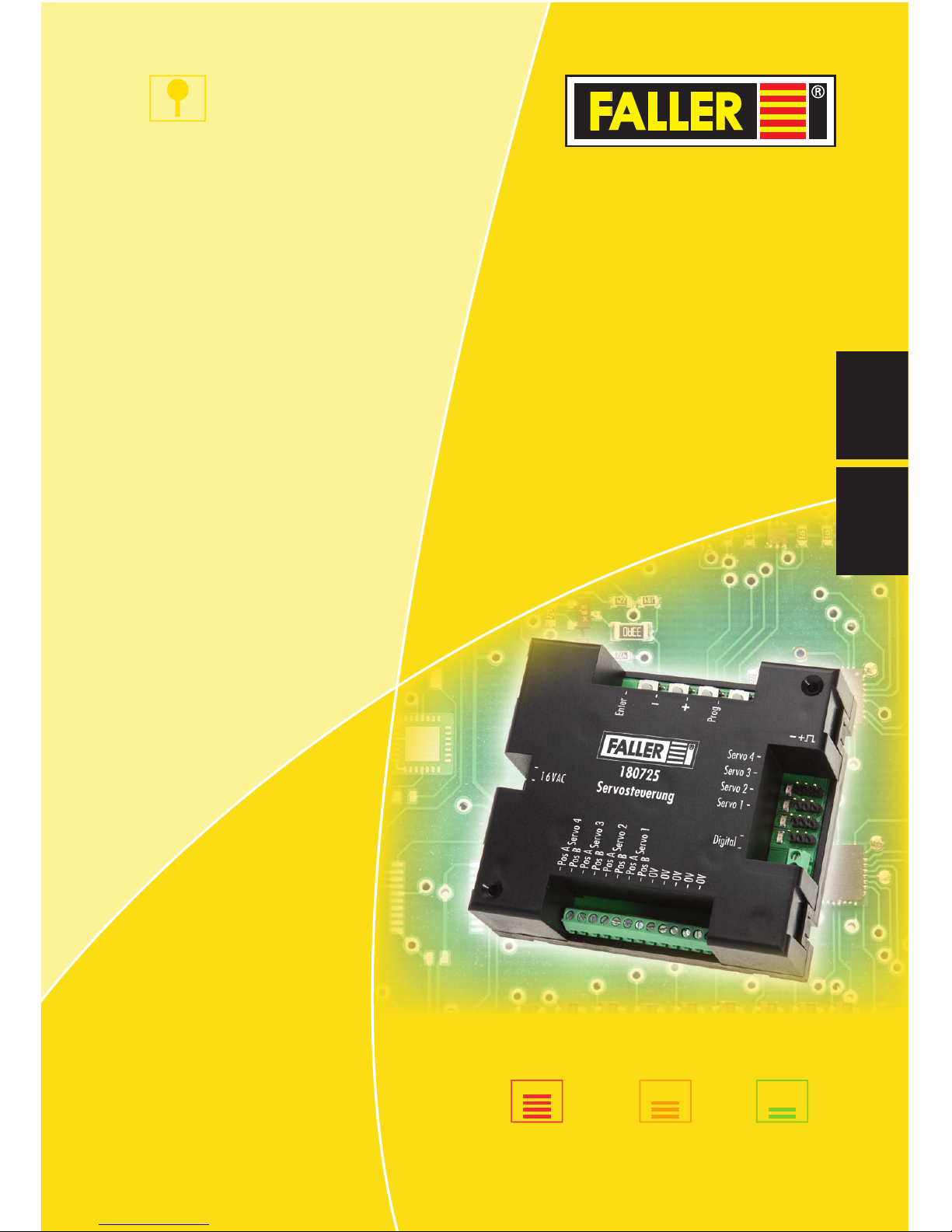
180725
Servosteuerung
Bedienungsanleitung
Instruction Manual
DE
EN
H0
TT
N
180725
Servo Control
ANLAGENBAU
Page 2

2
ANLAGENBAU
DE
Inhalt
1. Willkommen in der Welt von FALLER ............................................... 3
2. Sicherheit und Verantwortung .......................................................... 4
Bestimmungsgemäßer Gebrauch ...................................................... 4
Zu Ihrer Sicherheit ............................................................................ 4
Umweltgerecht entsorgen ................................................................ 5
3. Produktübersicht .............................................................................. 6
Lieferumfang ................................................................................... 6
Bedienelemente ............................................................................... 6
4. Anschließen ..................................................................................... 8
Servosteuerung anschließen ............................................................. 8
Servos anschließen ........................................................................... 9
Digitalzentrale anschließen ............................................................. 10
Taster anschließen .......................................................................... 11
5. Servos einstellen............................................................................. 12
Servos über Servosteuerung einstellen............................................ 12
Servos über Digitalzentrale einstellen ............................................. 14
Servos über Konfigurationsvariablen (CV) einstellen ....................... 17
6. Servos bedienen ............................................................................. 23
Servos über Servosteuerung bedienen ............................................ 23
Servos über Digitalzentrale bedienen.............................................. 23
7. Was tun wenn? .............................................................................. 24
8. Wissenswertes ............................................................................... 25
Servos ............................................................................................ 25
9. Technische Daten und Symbole ...................................................... 27
Elektrische Werte ........................................................................... 27
Digitale Daten ................................................................................ 27
Symbole ......................................................................................... 28
Zeichen .......................................................................................... 28
Page 3
3
Willkommen in der Welt von FALLER
ANLAGENBAU
DE
1. Willkommen in der Welt von FALLER
Herzlichen Glückwunsch – Sie sind fündig geworden!
Mit der Servosteuerung haben Sie eine Steuerung erworben, mit der Sie bis
zu vier handelsübliche Servos anschließen und getrennt voneinander ansteuern können. Diese können Sie benutzen, um zum Beispiel Weichenstellungen
zu ändern, Wasserkräne zu bewegen, Tore von Lokschuppen oder Schranken zu öffnen und zu schließen.
Sie können Servos entweder direkt über die Servosteuerung oder über eine
zusätzlich angeschlossene Digitalzentrale einstellen. Dabei können Sie bis
zu vier Haltepositionen des Servos, dessen Bewegungsgeschwindigkeit und
sogar eine Wippfunktion einstellen, die zum Beispiel Schranken an Bahnübergängen eine realistische Öffnen- und Schließen-Bewegung verleiht.
Die Servosteuerung arbeitet wie ein Weichendecoder und erhält in einer
Digitalzentrale für jeden Servo eine Magnetartikeladresse. Über die Magnetartikelsteuerung der Digitalzentrale können Sie die Servos in verschiedene
Haltepositionen bewegen. Die Servos können Sie außerdem mit Konfigurationsvariablen (CVs) über eine Digitalzentrale einstellen, die das DCCDatenformat beherrscht.
Viele kreative Ideen und viel Freude mit Ihrem Produkt wünscht Ihnen Ihre
Gebr. FALLER GmbH!
Page 4
4
Sicherheit und Verantwortung
ANLAGENBAU
DE
2. Sicherheit und Verantwortung
Bestimmungsgemäßer Gebrauch
Die Servosteuerung ist dazu bestimmt, Servos – wie sie im Modellbau üblich
sind – einzustellen und für mechanische Steuerungsaufgaben auf der Modellbahnanlage zu benutzen.
Für Schäden oder Mängel, die durch Nichtbeachten der Bedienungs anleitung
entstehen, entfällt die Gewährleistung.
Zu Ihrer Sicherheit
X
Lesen Sie die Bedienungsanleitung sorgfältig vor Gebrauch.
X
Beachten Sie die Sicherheitshinweise und Warnungen in der Bedienungsanleitung und am Produkt.
X
Informieren Sie ggf. Kinder über den Inhalt der Bedienungsanleitung
und über Gefahren bei der Verwendung des Produkts.
X
Betreiben Sie das Produkt nur in einwandfreiem Zustand.
X
Halten Sie die Bedienungsanleitung beim Produkt verfügbar.
X
Geben Sie das Produkt nur zusammen mit dieser Bedienungsanleitung
an Dritte weiter.
ACHTUNG
ACHTUNG kennzeichnet Gefahren,
die zu Sachschäden führen können.
Page 5

5
Sicherheit und Verantwortung
ANLAGENBAU
DE
Explosionsgefahr
Betrieb des Produkts in explosionsgefährdeten Umgebungen oder mit ungeeigneten Servos kann Explosionen auslösen und zu schweren Verletzungen
und Sachschäden führen.
X
Nicht in explosionsgefährdeten Umgebungen betreiben.
Korrosionsgefahr
Betrieb des Produkts in feuchten Räumen und Kontakt mit Wasser kann zu
Sachschäden führen.
X
Nur in trockenen Räumen betreiben.
X
Kontakt mit Wasser vermeiden.
Gefahr von Personen- und Sachschaden
Unsachgemäßer Betrieb des Produkts kann zu Verletzungen und Sachschäden führen.
X
Gehäuse nicht öffnen.
X
Wenn das Produkt nicht oder nicht mehr richtig funktioniert: Wenden
Sie sich an den FALLER-Kundendienst.
Umweltgerecht entsorgen
X
Beachten Sie die örtlichen Bestimmungen zur Abfallbeseitigung.
X
Entsorgen Sie die Akkus bei den dafür zuständigen und staatlich bestimmten Stellen.
Page 6
6
Produktübersicht
ANLAGENBAU
DE
3. Produktübersicht
Lieferumfang
Servosteuerung, Art.Nr. 180725
Bedienungsanleitung
Bedienelemente
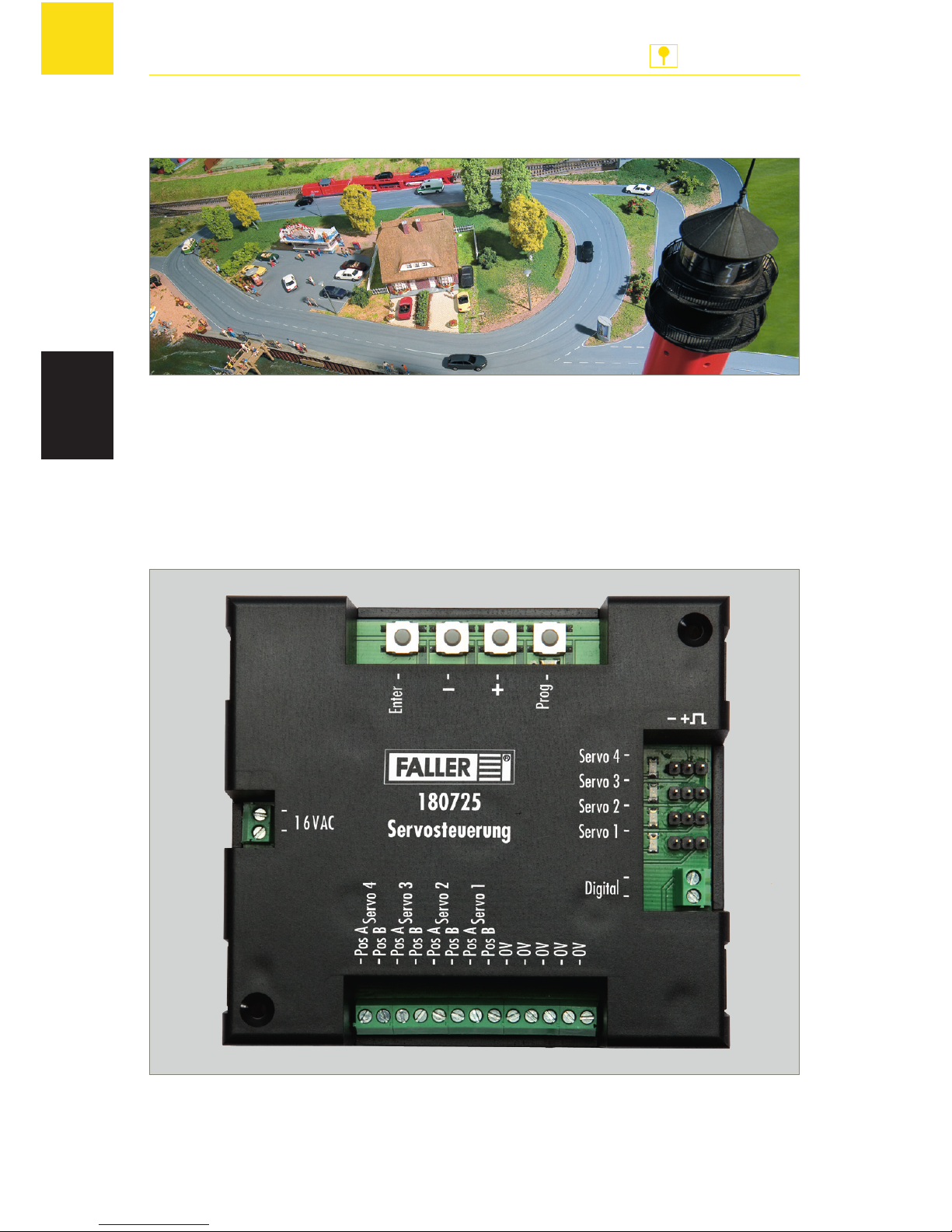
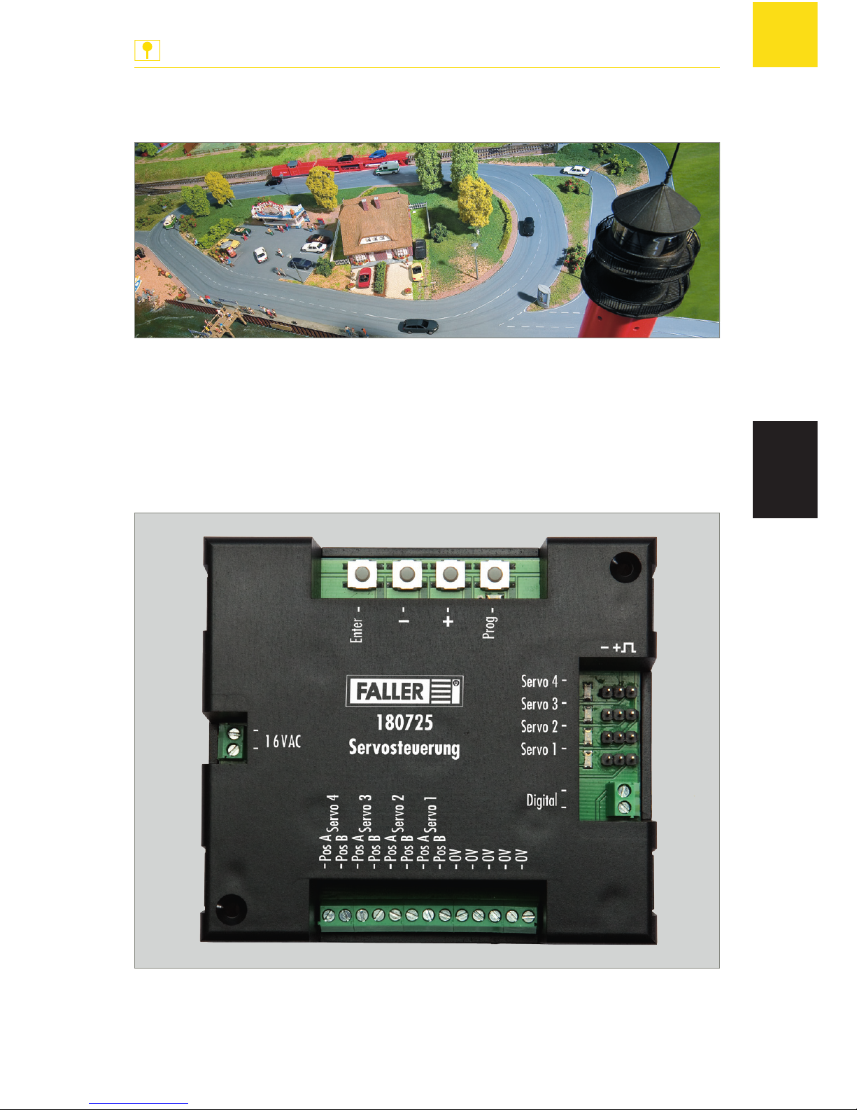
Abb. 1: Servosteuerung, Art.Nr. 180725
Page 7
7
Produktübersicht
ANLAGENBAU
DE
Anschlüsse Beschreibung
»16 VAC« Anschluss für die Spannungsversorgung
(16 V Wechselspannung)
»Servo 1« –
»Servo 4«
Anschlüsse mit Polbelegung für vier Servos
»Digital« Anschluss für eine Digitalzentrale
zur Programmierung des Servos
»Pos A Servo 1« –
»Pos A Servo 4«
Anschlüsse für Tasten, die bei den Servos jeweils
die erste Halteposition aufrufen ("rote Tasten")
»Pos B Servo 1« –
»Pos B Servo 4«
Anschlüsse für Tasten, die bei den Servos jeweils
die zweite Halteposition aufrufen ("grüne Tasten")
»0V« Anschlüsse für Masse (5x)
Tasten Beschreibung
»Enter« Eingaben bestätigen
»-« Minus-Taste
»+« Plus-Taste
»Prog« Programmiermodus aktivieren
LEDs Beschreibung
»Prog« Blinkt im Herzrhythmus, wenn die Servosteuerung
korrekt an die Stromversorgung angeschlossen ist
Leuchtet, wenn der Programmiermodus aktiv ist
»Servo 1« –
»Servo 4«
Leuchtet, wenn ein Servo im Programmiermodus
ausgewählt ist
HINWEIS: Die LEDs »Servo 1« – »Servo 4« haben im
Programmiermodus weitere Bedeutungen, die an den
entsprechenden Stellen beschrieben sind.
Page 8
8
Anschließen
ANLAGENBAU
DE
4. Anschließen
Servosteuerung anschließen
Die Servosteuerung wird mit 16V Wechselspannung betrieben.
Die notwendige Wechselspannung können Sie zum Beispiel mit dem
FALLER-Transformator 50 VA 50–60Hz, Art.Nr. 180641, erzeugen.
TIPP
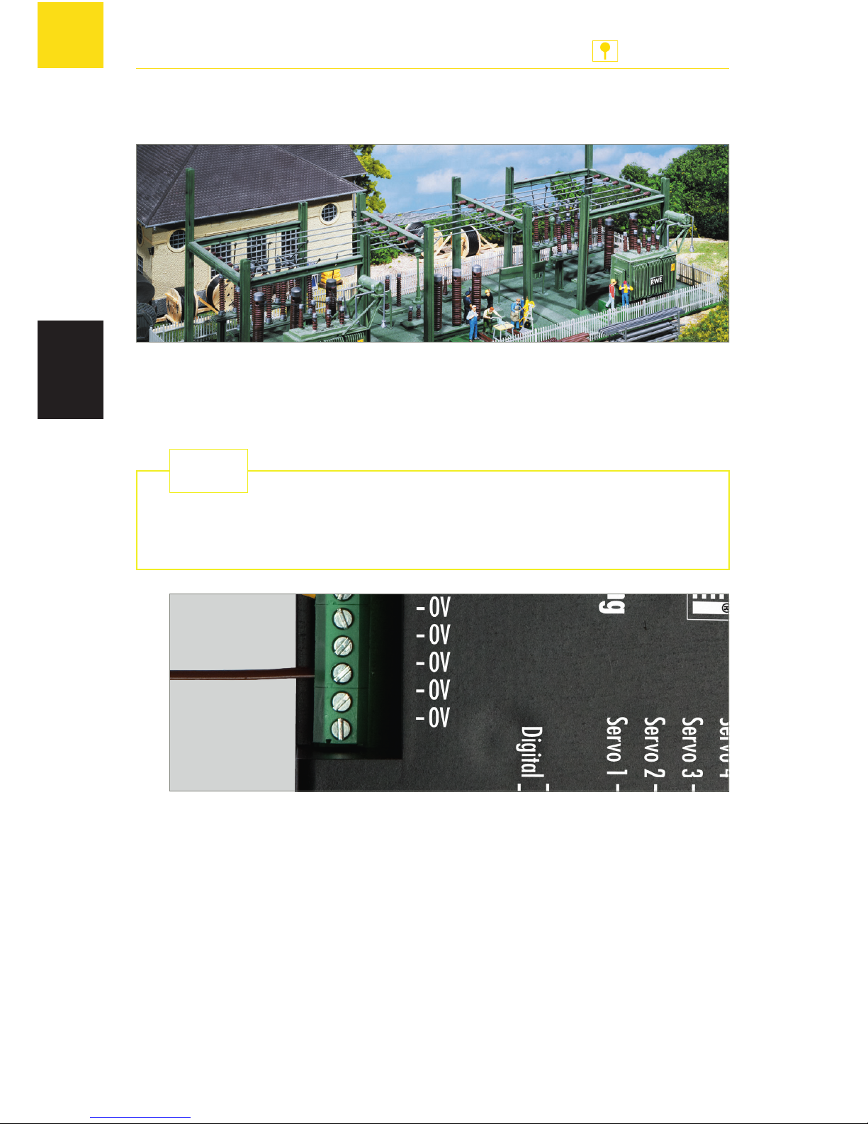
Abb. 2: Masse anschließen
X
Schließen Sie eine Leitung, die mit Masse verbunden ist, an einen der
Anschlüsse »0V« an der Servosteuerung an, siehe Abb. 2.
Page 9
9
Anschließen
ANLAGENBAU
DE
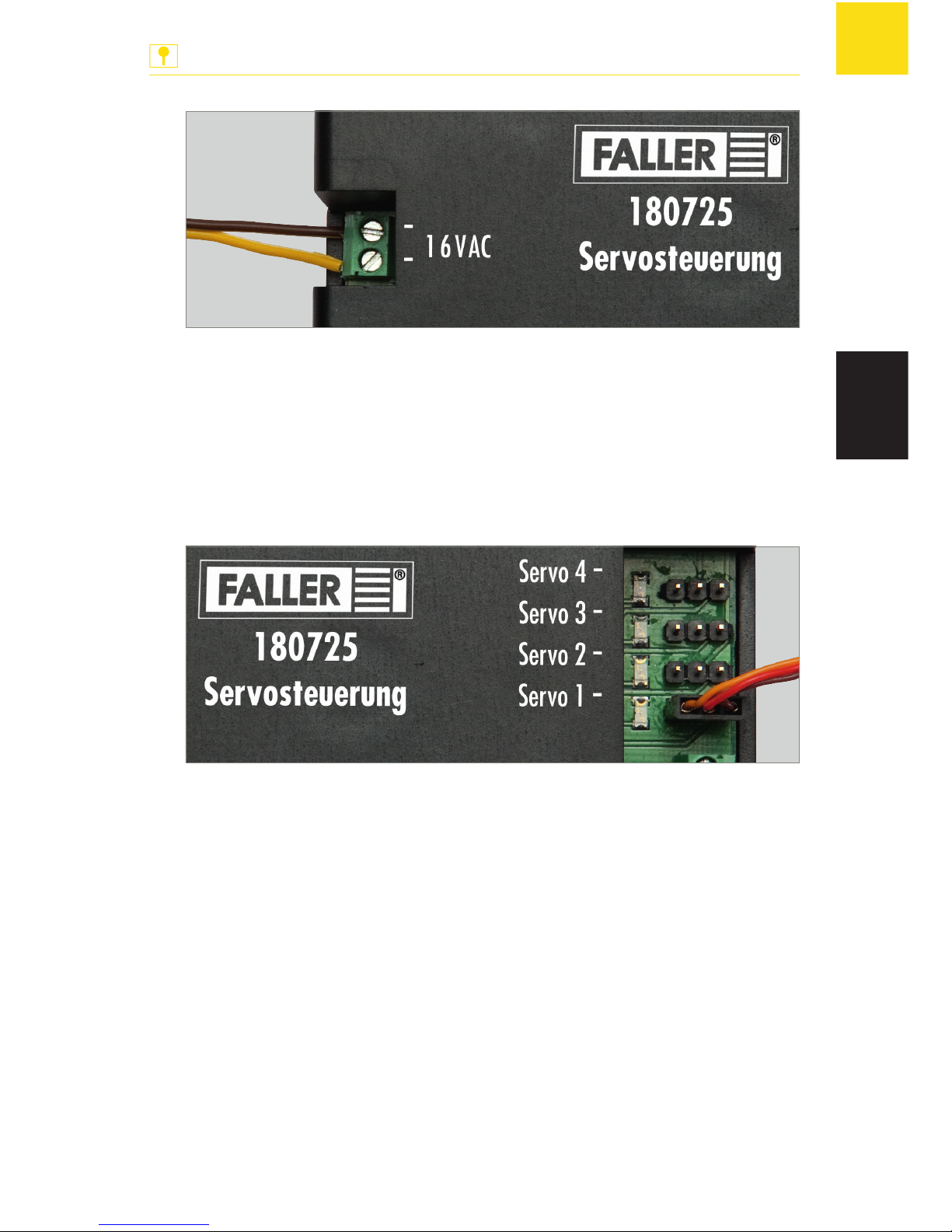
Abb. 3: Spannungsversorgung anschließen
X
Schließen Sie 16V Wechselspannung an den Anschluss »16 VAC« an
der Servosteuerung an, siehe Abb. 3.
Die LED »Prog« blinkt im Herzrhythmus.
Servos anschließen
Sie können bis zu vier Servos an die Servosteuerung anschließen.
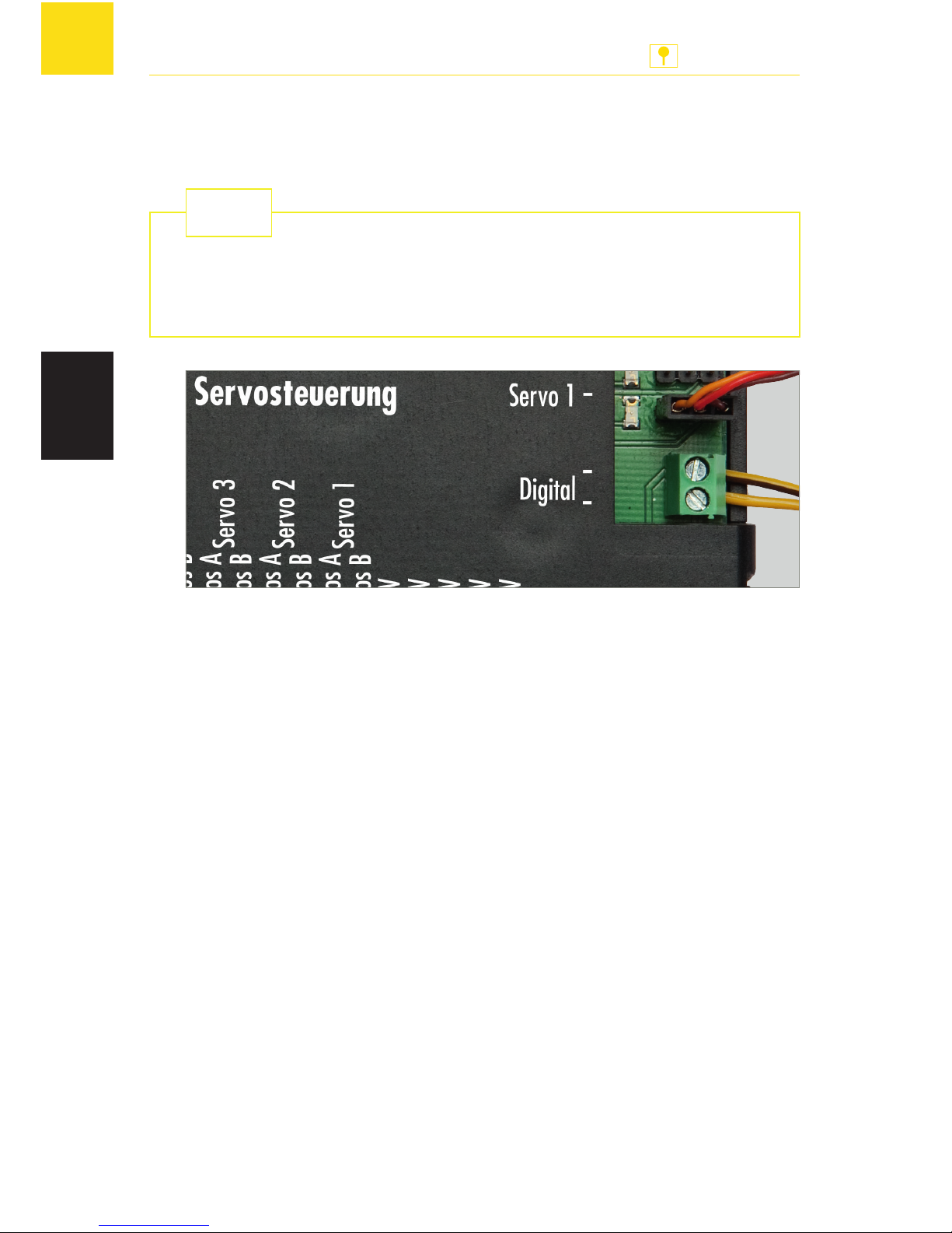
Abb. 4: Servos anschließen
HINWEIS: Die Anschlüsse »Servo 1« – »Servo 4« sind gegen Verpolung
geschützt. Wenn Sie die Anschlussleitung eines Servos aus Versehen falsch
angeschlossen haben, kann die Servosteuerung nicht auf den Servo zugreifen. Drehen Sie in diesem Fall den Stecker um 180°.
X
Schließen Sie einen oder mehrere Servos an einen der Anschlüsse
»Servo1« – »Servo4« an der Servosteuerung an, siehe Abb. 4.
Page 10
10
Anschließen
ANLAGENBAU
DE
Digitalzentrale anschließen
Die Servosteuerung ist kompatibel mit DCC- und Motorola-Digitalsystemen.
Wenn Sie die Servosteuerung an eine Digitalzentrale anschließen, können Sie die Servos über die Digitalzentrale auch dann noch bequem
einstellen, wenn die Servosteuerung bereits in Ihrer Anlage verbaut ist.
TIPP
Abb. 5: Digitalzentrale anschließen
HINWEIS: Eine Digitalzentrale und die Servosteuerung dürfen nicht an demselben Transformator angeschlossen sein.
X
Wenn Sie Servos über eine Digitalzentrale einstellen möchten, schließen
Sie die Servosteuerung mit dem Anschluss »Digital« an einen Programmiergleis-Anschluss einer Digitalzentrale an, siehe Abb. 5.
X
Wenn Sie Servos über eine Digitalzentrale bedienen möchten, schließen
Sie die Servosteuerung mit dem Anschluss »Digital« an einen Gleisausgang einer Digitalzentrale an, siehe Abb. 5.
Page 11
11
Anschließen
ANLAGENBAU
DE
Taster anschließen
Sie können für jede Servoposition einen Taster anschließen.
Abb. 6: Taster anschließen
X
Schließen Sie einen oder mehrere Taster an die Anschlüsse »Pos A Servo 1« –
»Pos A Servo 4« und »Pos B Servo 1« – »Pos B Servo 4« an der Servosteuerung an, siehe Abb. 6.
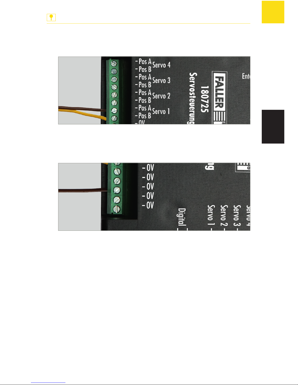
Abb. 7: Masse anschließen
X
Schließen Sie für jeden Taster den Masseanschluss des Tasters an einen
der Anschlüsse »0V« an der Servosteuerung an, siehe Abb. 7.
Page 12
12
Servos einstellen
ANLAGENBAU
DE
5. Servos einstellen
Mit der Servosteuerung können Sie Servos über drei Arten einstellen:
Servos über Servosteuerung einstellen
Servos über Digitalzentrale einstellen
Servos über Konfigurationsvariablen (CV) einstellen
Servos über Servosteuerung einstellen
Die Servos werden direkt über die Tasten an der Servosteuerung eingestellt.
Dabei können Sie die beiden Haltepositionen der ersten Adresse und die
Bewegungsgeschwindigkeiten der Servos einstellen.
Im Programmiermodus werden immer die folgenden Einstellmöglichkeiten
nacheinander durchlaufen:
Programmierpfad analog oder digital
Anschluss des gewünschten Servos
Erste Halteposition des Servos
Zweite Halteposition des Servos
Bewegungsgeschwindigkeit des Servos
HINWEIS: Sie können den Programmiermodus während der gesamten Programmierung mit der Taste »Prog« verlassen. Die Einstellungen, die bis dahin
vorgenommen wurden, werden nicht gespeichert.
Voraussetzungen:
Die Servosteuerung ist an die Spannungsversorgung angeschlossen.
Ein Servo ist an die Servosteuerung angeschlossen.
X
Drücken Sie die Taste »Prog«.
Die LED »Prog« leuchtet. Der Programmiermodus ist aktiv.
Page 13

13
Servos einstellen
ANLAGENBAU
DE
X
Drücken Sie die Taste »+«.
Der analoge Programmierpfad ist aktiv.
Die LED »Servo 1« leuchtet.
X
Wählen Sie mit den Tasten »+« und »-« den Anschluss des Servos, den
Sie einstellen möchten.
HINWEIS: Wenn sich der Servo nach dem nächsten Handlungsschritt nicht
bewegt, sind die Anschlüsse am Stecker verpolt. Drehen Sie in diesem Fall
den Stecker um 180°.
X
Drücken Sie die Taste »Enter«.
Der Servo, der an dem gewählten Anschluss angeschlossen ist, bewegt
sich kurz.
X
Stellen Sie mit den Tasten »+« und »-« die erste Halteposition des Servos ein (Halteposition "rot"). Wenn Sie die Tasten gedrückt halten,
können Sie auch große Positionsänderungen komfortabel vornehmen.
X
Drücken Sie die Taste »Enter«.
Der Servo bewegt sich zur zweiten Halteposition.
X
Stellen Sie mit den Tasten »+« und »-« die zweite Halteposition des Servos ein (Halteposition "grün"). Wenn Sie die Tasten gedrückt halten,
können Sie auch große Positionsänderungen komfortabel vornehmen.
X
Drücken Sie die Taste »Enter«.
Der Servo bewegt sich zwischen den beiden eingestellten Haltepositi-
onen hin und her.
X
Stellen Sie mit den Tasten »+« und »-« die Bewegungsgeschwindigkeit des Servos ein.
X
Drücken Sie die Taste »Enter«.
Die Einstellungen werden gespeichert.
Die LED des programmierten Servo-Anschlusses erlischt.
Die LED »Prog« blinkt im Herzrhythmus.
Page 14

14
Servos einstellen
ANLAGENBAU
DE
Servos über Digitalzentrale einstellen
Die Servos werden über eine Digitalzentrale eingestellt. Dabei können Sie
die beiden Haltepositionen der ersten Adresse und die Bewegungsgeschwindigkeiten der Servos einstellen.
Im Programmiermodus werden immer die folgenden Einstellmöglichkeiten
nacheinander durchlaufen:
Programmierpfad analog oder digital
Datenformat DCC oder Motorola
Anschluss des gewünschten Servos
Bedientasten an der Digitalzentrale
Temporäre Einstelltasten »+« und »-« an der Digitalzentrale
Erste Halteposition des Servos
Zweite Halteposition des Servos
Bewegungsgeschwindigkeit des Servos
Alternativ können Sie die Einstellungen auch mit einem anderen
Bediengerät durchführen, mit dem man Magnetartikel schalten kann.
Hierzu müssen Sie während der Programmierung zwei Tasten festlegen, die nur während der Programmierung der Servos von der
Servosteuerung verwendet werden. Sie können zwei beliebige Magnetartikeltasten verwenden, die während der Programmierung als
Tasten »+« und »-« dienen. Wenn die Programmierung abgeschlossen ist, löscht die Servosteuerung diese Einstellungen und die Tasten
können für Weichen oder Signale verwendet werden.
TIPP
HINWEISE:
Sie können den Programmiermodus während der gesamten Program-
mierung mit der Taste »Prog« verlassen. Die Einstellungen, die bis dahin
vorgenommen wurden, werden nicht gespeichert.
Wenn Sie das falsche Datenformat wählen, reagiert die Servosteuerung
nicht auf Tasteneingaben an der Digitalzentrale.
Voraussetzungen:
Die Servosteuerung ist an die Spannungsversorgung angeschlossen.
Die Servosteuerung ist an einen Programmiergleis-Anschluss einer Digital-
zentrale angeschlossen.
Ein Servo ist an die Servosteuerung angeschlossen.
Page 15

15
Servos einstellen
ANLAGENBAU
DE
X
Drücken Sie die Taste »Prog«.
Die LED »Prog« leuchtet. Der Programmiermodus ist aktiv.
X
Drücken Sie die Taste »-«.
Der digitale Programmierpfad ist aktiv.
Die LEDs »Servo 1« und »Servo 2« blinken.
X
Wählen Sie mit den Tasten »+« und »-« das gewünschte Datenformat.
Wenn die LEDs »Servo 1« und »Servo 2« blinken, ist das DCC-Daten-
format gewählt.
Wenn die LEDs »Servo 3« und »Servo 4« blinken, ist das Motorola-
Datenformat gewählt.
X
Drücken Sie die Taste »Enter«.
Die LED »Servo 1« leuchtet.
X
Wählen Sie mit den Tasten »+« und »-« den Anschluss des Servos, den
Sie einstellen möchten.
X
Drücken Sie die Taste »Enter«.
HINWEIS: Wenn sich der Servo nach dem nächsten Handlungsschritt nicht
bewegt, sind die Anschlüsse am Stecker verpolt. Drehen Sie in diesem Fall
den Stecker um 180°.
X
Drücken Sie an der Digitalzentrale eine der beiden Tasten einer Magnetartikeladresse, die den Servo später bewegen soll.
Der Servo bewegt sich kurz.
Sie haben die Bedientasten an der Digitalzentrale festgelegt.
HINWEIS: Die Tasten, die während der Programmierung als temporäre Tasten
»+« und »-« dienen sollen, dürfen nicht mit den vorher gewählten Bedientasten übereinstimmen. Wählen Sie für jede temporäre Taste »+« und »-«
eine eigene Magnetartikeladresse.
X
Drücken Sie an der Digitalzentrale die Taste, die während der Programmierung als temporäre Taste »+« dienen soll.
Der Servo bewegt sich kurz.
X
Drücken Sie an der Digitalzentrale die Taste, die während der Programmierung als temporäre Taste »-« dienen soll.
Der Servo bewegt sich kurz.
X
Bringen Sie den Servo mit einer Bedientaste an der Digitalzentrale in
die erste Halteposition des Servos (zum Beispiel Halteposition "rot").
X
Stellen Sie mit den temporären Tasten »+« und »-« an der Digitalzentrale die erste Halteposition des Servos ein (Halteposition "rot").
Page 16

16
Servos einstellen
ANLAGENBAU
DE
X
Bringen Sie den Servo mit der anderen Bedientaste an der Digitalzentrale
in die zweite Halteposition des Servos (Halteposition "grün").
X
Stellen Sie mit den temporären Tasten »+« und »-« an der Digitalzentrale die zweite Halteposition des Servos ein (Halteposition "grün").
X
Speichern Sie die beiden Haltepositionen des Servos, indem Sie mit den
Bedientasten jeweils drei Mal zwischen den Haltepositionen wechseln,
ohne die Einstellungen zu verändern.
Der Servo bewegt sich zwischen den beiden eingestellten Haltepositionen hin und her.
X
Stellen Sie mit den temporären Tasten »+« und »-« an der Digitalzentrale die Bewegungsgeschwindigkeit des Servos ein.
X
Drücken Sie eine der beiden Bedientasten.
Die Einstellungen werden gespeichert.
Die LED des programmierten Servo-Anschlusses erlischt.
Die LED "Prog" blinkt im Herzrhythmus.
Page 17
17
Servos einstellen
ANLAGENBAU
DE
Servos über Konfigurationsvariablen (CV) einstellen
Die Servos werden mit Konfigurationsvariablen (CV) über eine Digitalzentrale eingestellt, die das DCC-Datenformat beherrscht. Dabei können Sie die
beiden Haltepositionen der ersten Adresse und die Bewegungsgeschwindigkeiten der Servos sowie die Wipp-Funktion einstellen.
Über eine zweite Adresse können Sie auch zwei weitere, getrennt einstellbare Haltepositionen einstellen. Somit können Sie zum Beispiel Wasserkräne
in vier Haltepositionen bringen.
ACHTUNG
Sachschaden durch falsche Einstellungen oder falsche Programmierung.
Servosteuerung und Servos funktionieren nicht mehr ordnungs gemäß
oder werden zerstört.
X
Nur programmieren, wenn ausreichende CV-Programmierkenntnisse
vorhanden sind.
X
Lesen und beachten Sie die Bedienungsanleitung der Digitalzentrale.
Voraussetzungen:
Die Servosteuerung ist an die Spannungsversorgung angeschlossen.
Die Servosteuerung ist an einen Programmiergleis-Anschluss einer Digital-
zentrale angeschlossen, die das DCC-Datenformat beherrscht.
Ein Servo ist an die Servosteuerung angeschlossen.
HINWEIS: Entnehmen Sie der Bedienungsanleitung der Digitalzentrale, wie
Sie bei der Programmierung mit der Digitalzentrale vorgehen müssen.
X
Wählen Sie an der Digitalzentrale die Funktion, mit der Sie Konfigurationsvariablen einstellen können.
X
Stellen Sie die entsprechenden Konfigurationsvariablen an der Digitalzentrale ein. Verwenden Sie hierzu die Tabelle „Übersicht über alle
Konfigurationsvariablen“ auf Seite 19 und den Abschnitt „Beispiel: WippFunktion einstellen“ auf Seite 18.
X
Übertragen Sie die eingestellten Werte an die Servosteuerung.
Die Einstellungen sind gespeichert.
Page 18
18
Servos einstellen
ANLAGENBAU
DE
Beispiel: Wipp-Funktion einstellen
Dieses Beispiel beschreibt anhand der Wipp-Funktion, wie man die Servos
über Konfigurationsvariablen einstellen kann. Andere Einstellungen an den
Servos können Sie nach demselben Prinzip vornehmen.
Mit der Wipp-Funktion können Sie zum Beispiel Schranken oder Toren,
die mit Servos bewegt werden, beim Öffnen- und Schließen eine WippBewegung hinzufügen und Ihnen somit eine realistische Bewegung verleihen. Wenn ein Servo eine Halteposition erreicht hat, wippt er zyklisch
abklingend nach. Sie können die Wipp-Bewegung über die Wipp-Zeit
und den Wipp-Ausschlag einstellen.
TIPP
HINWEISE:
Wenn Sie die Wipp-Funktion verwenden, kann der Servo nur die Halte-
positionen der 1. Adresse anfahren. Die Haltepositionen der 2. Adresse
werden nicht mehr angefahren.
Wenn Sie die CV des Wipp-Ausschlags auf die Werte 0 oder 127 (mini-
maler und maximaler Wert) stellen, funktioniert die Wipp-Funktion nicht.
In diesem Beispiel gehen wir davon aus, dass ein Servo am Anschluss
»Servo 1« an der Servosteuerung angeschlossen ist.
X
Wählen Sie an der Digitalzentrale die Funktion, mit der Sie Konfigurationsvariablen einstellen können.
X
Stellen Sie mit der CV Nr. 122 die erste Halteposition des Servos ein
(Halteposition "rot"), zum Beispiel den Wert "40".
X
Stellen Sie mit der CV Nr. 123 die zweite Halteposition des Servos ein
(Halteposition "grün"), zum Beispiel den Wert "100".
X
Stellen Sie mit der CV Nr. 125 den Wipp-Ausschlag der ersten Halteposition des Servos ein (Halteposition "rot"), zum Beispiel den Wert "35".
X
Stellen Sie mit der CV Nr. 126 die Wipp-Zeit der ersten Halteposition des
Servos ein (Halteposition "rot"), zum Beispiel den Wert "90".
X
Stellen Sie mit der CV Nr. 127 den Wipp-Ausschlag der zweiten Halteposition des Servos ein (Halteposition "grün"), zum Beispiel den Wert "70".
X
Stellen Sie mit der CV Nr. 128 die Wipp-Zeit der zweiten Halteposition
des Servos ein (Halteposition "grün"), zum Beispiel den Wert "125".
X
Übertragen Sie die eingestellten Werte an die Servosteuerung.
Die Einstellungen sind gespeichert.
Page 19
19
Servos einstellen
ANLAGENBAU
DE
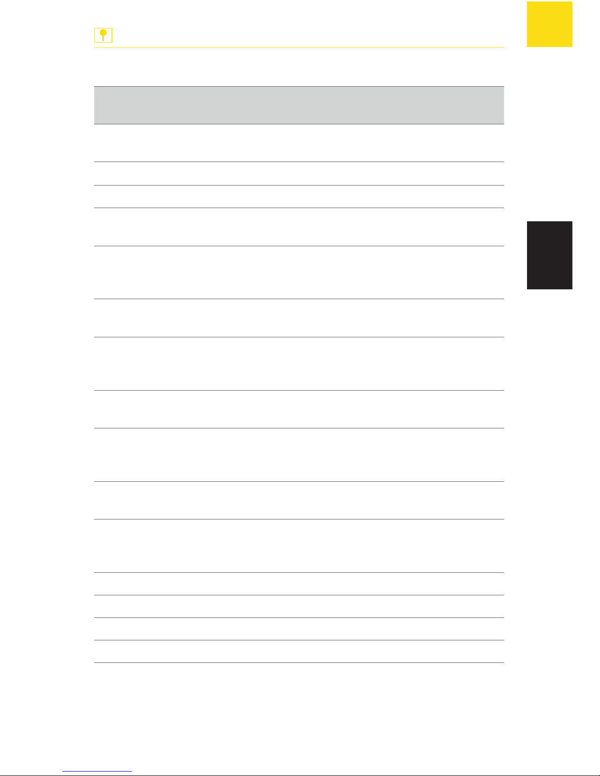
Übersicht über alle Konfigurationsvariablen
CV Beschreibung Werte-
bereich
Werkseinstellung
112 Software-Version - unter-
schiedlich
113 Herstellercode (Manufacture ID) - 85
119 Decoder Konfiguration 0-15 15
Bit0 = 1: Spannung an Ausgang 1
ist immer eingeschaltet
Bit0 = 0: Spannung an Ausgang 1
ist nur bei ServoBewegung eingeschaltet
Bit1 = 1: Spannung an Ausgang 2
ist immer eingeschaltet
Bit1 = 0: Spannung an Ausgang 2
ist nur bei ServoBewegung eingeschaltet
Bit2 = 1: Spannung an Ausgang 3
ist immer eingeschaltet
Bit2 = 0: Spannung an Ausgang 3
ist nur bei ServoBewegung eingeschaltet
Bit3 = 1: Spannung an Ausgang 4
ist immer eingeschaltet
Bit3 = 0: Spannung an Ausgang 4
ist nur bei ServoBewegung eingeschaltet
Bit4: Ist nicht verwendet
Bit5: Ist nicht verwendet
Bit7 = 0: DCC-Betrieb
Bit7 = 1: Motorola-Betrieb
Page 20
20
Servos einstellen
ANLAGENBAU
DE
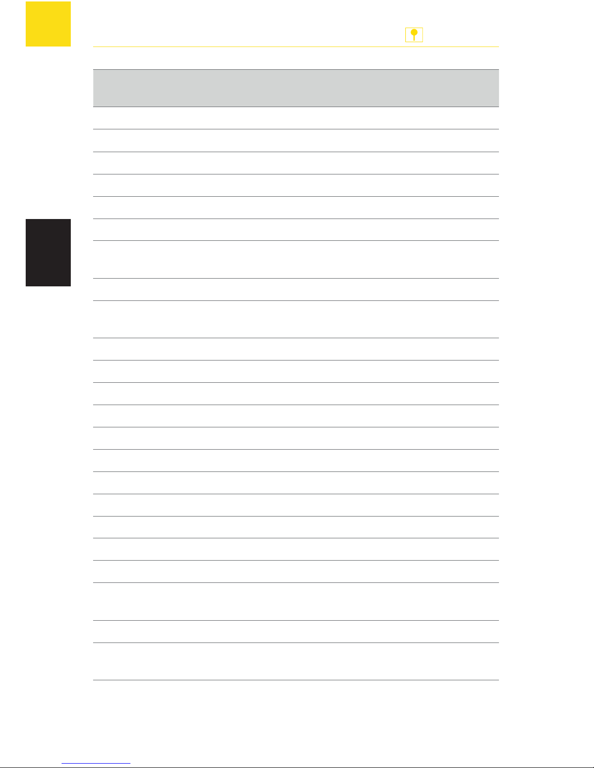
CV Beschreibung Werte-
bereich
Werkseinstellung
Anschluss »Servo 1«
120 HighByte Adresse 1 0-8 0
121 LowByte Adresse 1 0-255 1*
122 Halteposition "rot" Adresse 1 0-127 30
123 Halteposition "grün" Adresse 1 0-127 95
124 Stellzeit 0-255 40
125 Wipp-Ausschlag Halteposition "rot"
Adresse 1
0-127 0
126 Wipp-Zeit Halteposition "rot" Adresse 1 0-255 0
127 Wipp-Ausschlag Halteposition "grün"
Adresse 1
0-127 0
128 Wipp-Zeit Halteposition "grün" Adresse 1 0-255 0
160 HighByte Adresse 2 0-8 0
161 LowByte Adresse 2 0-255 0
162 Halteposition "rot" Adresse 2 0-127 0
163 Halteposition "grün" Adresse 2 0-127 0
Anschluss »Servo 2«
130 HighByte Adresse 1 0-8 0
131 LowByte Adresse 1 0-255 3*
132 Halteposition "rot" Adresse 1 0-127 30
133 Halteposition "grün" Adresse 1 0-127 95
134 Stellzeit 0-255 40
135 Wipp-Ausschlag Halteposition "rot"
Adresse 1
0-127 0
136 Wipp-Zeit Halteposition "rot" Adresse 1 0-255 0
137 Wipp-Ausschlag Halteposition "grün"
Adresse 1
0-127 0
Page 21
21
Servos einstellen
ANLAGENBAU
DE
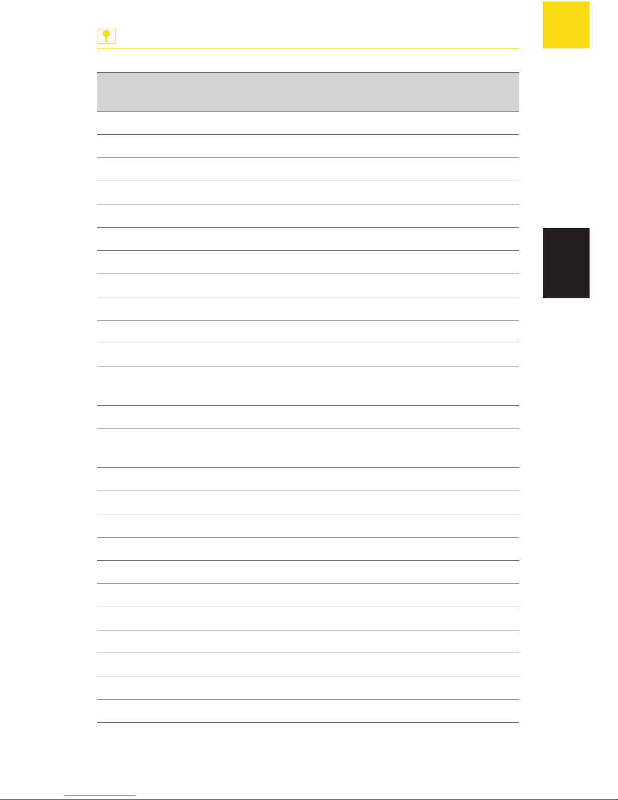
CV Beschreibung Werte-
bereich
Werkseinstellung
138 Wipp-Zeit Halteposition "grün" Adresse 1 0-255 0
170 HighByte Adresse 2 0-8 0
171 LowByte Adresse 2 0-255 0
172 Halteposition "rot" Adresse 2 0-127 0
173 Halteposition "grün" Adresse 2 0-127 0
Anschluss »Servo 3«
140 HighByte Adresse 1 0-8 0
141 LowByte Adresse 1 0-255 5*
142 Halteposition "rot" Adresse 1 0-127 30
143 Halteposition "grün" Adresse 1 0-127 95
144 Stellzeit 0-255 40
145 Wipp-Ausschlag Halteposition "rot"
Adresse 1
0-127 0
146 Wipp-Zeit Halteposition "rot" Adresse 1 0-255 0
147 Wipp-Ausschlag Halteposition "grün"
Adresse 1
0-127 0
148 Wipp-Zeit Halteposition "grün" Adresse 1 0-255 0
180 HighByte Adresse 2 0-8 0
181 LowByte Adresse 2 0-255 0
182 Halteposition "rot" Adresse 2 0-127 0
183 Halteposition "grün" Adresse 2 0-127 0
Anschluss »Servo 4«
150 HighByte Adresse 1 0-8 0
151 LowByte Adresse 1 0-255 7*
152 Halteposition "rot" Adresse 1 0-127 30
153 Halteposition "grün" Adresse 1 0-127 95
154 Stellzeit 0-255 40
Page 22
22
Servos einstellen
ANLAGENBAU
DE
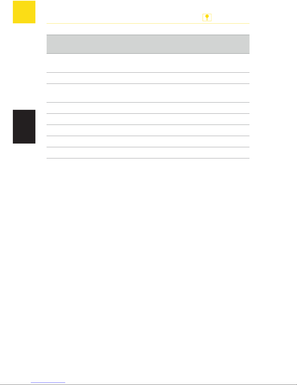
CV Beschreibung Werte-
bereich
Werkseinstellung
155 Wipp-Ausschlag Halteposition "rot"
Adresse 1
0-127 0
156 Wipp-Zeit Halteposition "rot" Adresse 1 0-255 0
157 Wipp-Ausschlag Halteposition "grün"
Adresse 1
0-127 0
158 Wipp-Zeit Halteposition "grün" Adresse 1 0-255 0
190 HighByte Adresse 2 0-8 0
191 LowByte Adresse 2 0-255 0
192 Halteposition "rot" Adresse 2 0-127 0
193 Halteposition "grün" Adresse 2 0-127 0
Tab. 1: Übersicht über alle Konfigurationsvariablen (CV).
* HINWEIS: Wenn Sie eine Motorola-Digitalzentrale verwenden, sind die
werkseitig eingestellten Adressen der Konfigurationsvariablen 121, 131, 141
und 151 nicht verfügbar.
Page 23
23
Servos bedienen
ANLAGENBAU
DE
6. Servos bedienen
Mit der Servosteuerung können Sie Servos auf zwei Arten bedienen:
Servos über Servosteuerung bedienen
Servos über Digitalzentrale bedienen
Servos über Servosteuerung bedienen
Sie können Servos, die an der Servosteuerung angeschlossen sind, über die
Servosteuerung bedienen.
Voraussetzungen:
Die Servosteuerung ist an die Spannungsversorgung angeschlossen.
Ein Servo ist an die Servosteuerung angeschlossen.
Für jede Servoposition ist ein Taster an der Servosteuerung angeschlossen.
Der Servo wurde eingestellt.
X
Drücken Sie einen Taster, der an der Servosteuerung angeschlossen ist.
Servos über Digitalzentrale bedienen
Sie können einen Servo bequem über eine Digitalzentrale bedienen.
Voraussetzungen:
Die Servosteuerung ist an die Spannungsversorgung angeschlossen.
Die Servosteuerung ist an einen Gleisausgang einer Digitalzentrale
angeschlossen.
Ein Servo ist an die Servosteuerung angeschlossen.
Der Servo wurde über die Digitalzentrale eingestellt.
X
Drücken Sie eine Bedientaste, die Sie beim Einstellen des Servos über die
Digitalzentrale programmiert haben, siehe Kapitel „Servos über Digital-
zentrale einstellen“, Seite 14.
Page 24
24
Was tun wenn?
ANLAGENBAU
DE
7. Was tun wenn?
Der direkte Draht zum FALLER-Kundendienst:
Telefon + 49 (0) 77 23 / 651-106
E-Mail [email protected]
TIPP
Problem Mögliche Ursache Behebung
Ein Servo
funktioniert
nicht.
Die Servosteuerung
ist nicht an die Spannungsversorgung
angeschlossen.
X
Schließen Sie 16V Wechselspannung an den Anschluss
»16 VAC« an der Servosteuerung an.
Der Stecker des Servos
ist verpolt.
X
Drehen Sie den Stecker des
Servos um 180°.
Die WippFunktion
funktioniert
nicht.
Die Konfigurationsvariable des WippAusschlags ist auf die
Werte 0 oder 127
(minimaler und maximaler Wert) eingestellt.
Dadurch kann der
Servo die Wipp-Bewegung nicht ausführen.
X
Stellen Sie Werte ein, die
größer als 0 und kleiner als
127 sind.
Tab. 2: Was tun wenn?
Page 25
25
Wissenswertes
ANLAGENBAU
DE
8. Wissenswertes
Servos
Was ist ein Servo?
Ein Servo ist ein Gerät, das Steuerbefehle in mechanische Bewegungen
umsetzen kann.
Typen
Im Modellbau spricht man von Analog- und Digitalservos. Bei einem Analogservo ist die Elektronik analog aufgebaut. Bei einem Digitalservo wird die
Motorposition digital erfasst und durch eine geeignete Rechnerschaltung mit
einem Sollwert verglichen. Digitalservos haben eine höhere Winkelauflösung
und die Servoposition wird schneller und präziser geregelt. Digitalservos lassen sich häufig auch umprogrammieren, wodurch sich, je nach Servomodell,
die Geschwindigkeit, der Überlastschutz und ähnliches an die Anwendung
anpassen lassen. Allerdings sind bei Digitalservos der Bedarf an Hilfsenergie
und auch der Preis höher als bei Analogservos.
Aufbau
Ein Servo besteht aus einer Antriebseinheit und einer Ansteuerungseinheit,
wie zum Beispiel ein Elektromotor mit Steuerelektronik. Der Motor muss
sich in beide Richtungen drehen können und die aktuelle Drehposition des
Motors muss bestimmt werden können. Der elektrische Anschluss eines Servos erfolgt über drei Leitungen. Zwei für die Betriebsspannung ("Plus" und
"Minus") und eine für den Impuls ("Sollwert").
Page 26

26
Wissenswertes
ANLAGENBAU
DE
Funktionsweise
Servos – insbesondere Modellbau-Servos – werden über Pulsweitenmodulation angesprochen. Die Pulsweitenmodulation wird bei Servos auch PulsPausen-Modulation genannt. Die Pulsbreite stellt dabei den Sollwert dar.
Dieser Wert wird zyklisch, bei den meisten Servos alle 20 ms, wiederholt
und muss sich zwischen 1 ms (ganz links) bis 2 ms (ganz rechts) befinden.
Die Auflösung sowie die genauen Zeitwerte sind jedoch meist von Servo zu
Servo unterschiedlich. Manche Servos – vor allem Digitalservos – erlauben
auch einen Betrieb außerhalb des 1 ms bis 2 ms Bereichs. Dann lassen sich
ausnahmsweise Winkeländerungen bis etwa 180 Grad erzielen.
Zum genauen Erfassen der Motorposition ist jeder Servo mit einer Messeinrichtung versehen, welche die aktuelle Position des Motors bestimmt, z. B.
den zurückgelegten Drehwinkel bezüglich einer Anfangsposition. Diese Messung erfolgt über einen Drehgeber, z. B. über einen Resolver, einen Inkrementalgeber oder einen Absolutwertgeber.
Eine elektronische Regelung vergleicht das Signal des Drehgebers mit dem
vorgegebenen Sollwert. Liegt eine Abweichung vor, so wird der Motor in
diejenige Richtung gedreht, die einen geringeren Verfahrweg zum Sollwert
sicherstellt. Dies führt dazu, dass sich die Abweichung verringert. Die Prozedur wiederholt sich solange, bis der aktuelle Wert inkrementell oder via
Approximation innerhalb der Toleranzgrenzen des Sollwerts liegt. Diese Positionsregelung ist der einfachste Fall. Alternativ können über dieses Prinzip
auch Drehmoment und Geschwindigkeit geregelt werden. Dadurch sind
zum Beispiel gleichmäßige Fahrprofile bei schwankenden Lasten möglich.
Wollen Sie noch mehr wissen? Stillen Sie Ihren Wissensdurst auf
unserer Internetseite www.faller.de. Dort finden Sie interessante Hin-
tergrundinformationen und viele kreative Anregungen rund um das
Thema Modellbau.
TIPP
Page 27
27
Technische Daten und Symbole
ANLAGENBAU
DE
9. Technische Daten und Symbole
Elektrische Werte
Bezeichnung Wert
Spannungsversorgung 16 V Wechselspannung
Frequenzbereich 50/60 Hz
Gesamtbelastung 700 mA
Belastung je Servoausgang 700 mA
Zugelassene Servos Alle handelsüblichen Standard-Servos
Anzahl anschließbare Servos 4 Servos
Tab. 3: Elektrische Werte
Digitale Daten
Bezeichnung Wert
Schaltadressen 2 Schaltadressen
Adressbereich 1-2048
Pulsbreite der Steuerimpulse,
die die Digitalzentrale ausgibt
zwischen 1 und 2 ms
Digitalformate DCC
Motorola
Tab. 4: Digitale Daten
Page 28
28
Technische Daten und Symbole
ANLAGENBAU
DE
Symbole
Symbol Bedeutung
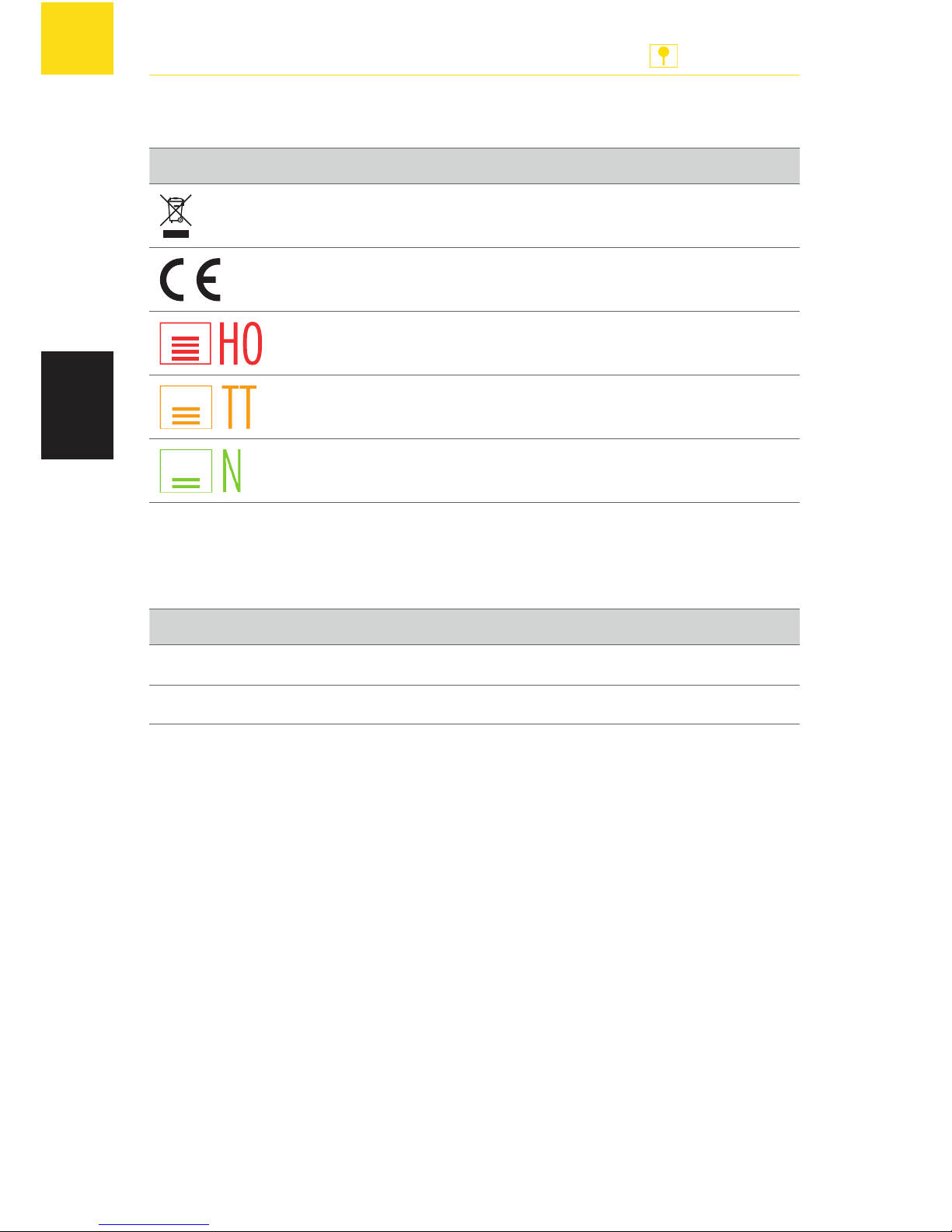
Das Produkt unterliegt der europäischen Richtlinie 2002/96/EC
CE-Konformitätskennzeichen
1:87/H0/Spurweite 16,5 mm
1:120/TT/Spurweite 12 mm
1:160/N/Spurweite 9 mm
Tab. 5: Symbole
Zeichen
Zeichen Bedeutung
X
Handlungsaufforderung
g
Aufzählung
Tab. 6: Zeichen
Page 29

29
ANLAGENBAU
EN
Contents
1. Welcome to FALLER’s world ........................................................... 30
2. Safety and responsibility ................................................................. 31
Proper use...................................................................................... 31
For your safety ............................................................................... 31
Environmentally friendly disposal ................................................... 32
3. General view of product ................................................................. 33
Articles supplied ............................................................................. 33
Operating elements ....................................................................... 33
4. Connection .................................................................................... 35
Connect the Servo Control ............................................................. 35
Connecting servos.......................................................................... 36
Connecting a digital control unit .................................................... 37
Connecting push buttons ............................................................... 38
5. Presetting servos ............................................................................ 39
Presetting servos via the Servo Control .......................................... 39
Presetting servos via a digital control unit ....................................... 41
Presetting servos via configuration variables (CV) .......................... 44
6. Positioning servos .......................................................................... 50
Positioning servos via the Servo Control ......................................... 50
Positioning servos via a digital control unit ..................................... 50
7. How to deal with problems ............................................................ 51
8. Interesting facts ............................................................................. 52
Servos ............................................................................................ 52
9. Technical data and symbols ............................................................ 54
Power supply ................................................................................. 54
Digital data .................................................................................... 54
Symbols ......................................................................................... 55
Signs ............................................................................................ 55
Page 30
30
Welcome to FALLER’s world
ANLAGENBAU
EN
1. Welcome to FALLER’s world
Congratulations – You have found the right thing!
The Servo Control you have acquired is a control system that will allow you
to connect and actuate up to four commercially available servos independently of each other. You may want to use such servos to change the position of points for instance, to move swivel water spouts, or to open and shut
barriers of level-crossings and gates of engine sheds.
Servos can be preset either directly through that Servo Control or via an
additional digital control unit connected to it. On doing so, you will be able
to preset up to four hold positions of the servo, its motion rate and even a
rocking function that imparts the barriers of level crossings a very realistic
opening and shutting motion.
Your Servo Control operates like a points decoder and is allocated within a
digital control unit a coil item address for each servo. The coil item control
within the digital control unit will then allow you to move the servos to various hold positions. Servos can also be preset using configuration variables
(CV) by means of a digital control unit that supports the DCC data format.
Gebr. FALLER GmbH wishes you a lot of creative ideas and plenty of fun
with your new acquisition!
Page 31
31
Safety and responsibility
ANLAGENBAU
EN
2. Safety and responsibility
Proper use
The Servo Control is designed to preset servos – like those common in
model making – and to use them for mechanical control tasks on a model
railway installation.
The guarantee offered will not apply to any damage or defect resulting from
the non-observance of the directions given in the present instruction manual.
For your safety
X
Carefully read through the instruction manual before use.
X
Pay attention to the safety recommendations and warnings given in the
instruction manual or provided on the product.
X
Inform children of the contents of the instruction manual, if necessary,
and of the potential hazards related to the use of the product.
X
Use the product only when it is in perfect condition.
X
Always retain the instruction manual available near to the product itself.
X
Hand over the product to any third person only together with the present
instruction manual.
NOTICE
NOTICE identifies hazards
that may result in property damage.
Page 32

32
Safety and responsibility
ANLAGENBAU
EN
Explosion hazard
Using the product in explosive environments or with unsuitable servos may
trigger explosions and cause severe injuries and property damage.
X
Do not use the product in explosive environments.
Corrosion hazard
Using the product in moist rooms or any contact of the product with water
may cause property damage.
X
Use only in dry rooms.
X
Avoid any contact with water.
Risk of physical injury and property damage
Improper use of the product may cause physical injury and property damage.
X
Do not open the enclosure.
X
If the product does not operate correctly or does not operate at all:
Consult FALLER’s customer service department.
Environmentally friendly disposal
X
Comply with the local regulations applying to waste disposal.
X
Dispose of rechargeable batteries via the qualified collecting points
authorized by your government.
Page 33
33
General view of product
ANLAGENBAU
EN
3. General view of product
Articles supplied
Servo Control, Art. no. 180725
Instruction manual
Operating elements
Fig. 1: Servo Control, Art. no. 180725
Page 34
34
General view of product
ANLAGENBAU
EN
Ports Description
»16 VAC« Port for the supply voltage
(16 V alternating voltage)
»Servo 1« to
»Servo 4«
Ports with specific pin assignment, for four servos
»Digital« Port for a digital control unit to program the servo
»Pos A Servo 1« to
»Pos A Servo 4«
Ports for keys that call up the first hold position
in the respective servos (“red keys”)
»Pos B Servo 1« to
»Pos B Servo 4«
Ports for keys that call up the second hold position
in the respective servos (“green keys”)
»0V« Ports for earthing (5x)
Keys Description
»Enter« To confirm inputs
»-« »Minus sign key«
»+« »Plus sign key«
»Prog« To activate the programming mode
LEDs Description
»Prog« Flashes at lower heart rate whenever the Servo
Control is properly connected to the power supply
Lights up whenever the programming mode is acti-
vated
»Servo 1« to
»Servo 4«
Lights up whenever a servo is selected in the programming mode
ADVICE: »Servo 1« to »Servo 4« LEDs have in
programming mode further meanings that will be
described in the relevant place.
Page 35
35
Connection
ANLAGENBAU
EN
4. Connection
Connect the Servo Control
The Servo Control operates on 16 V alternating voltage.
The required alternating voltage can be made available using
FALLER 50 VA, 50–60 Hz transformer, Art. no. 180641, for instance.
TIP
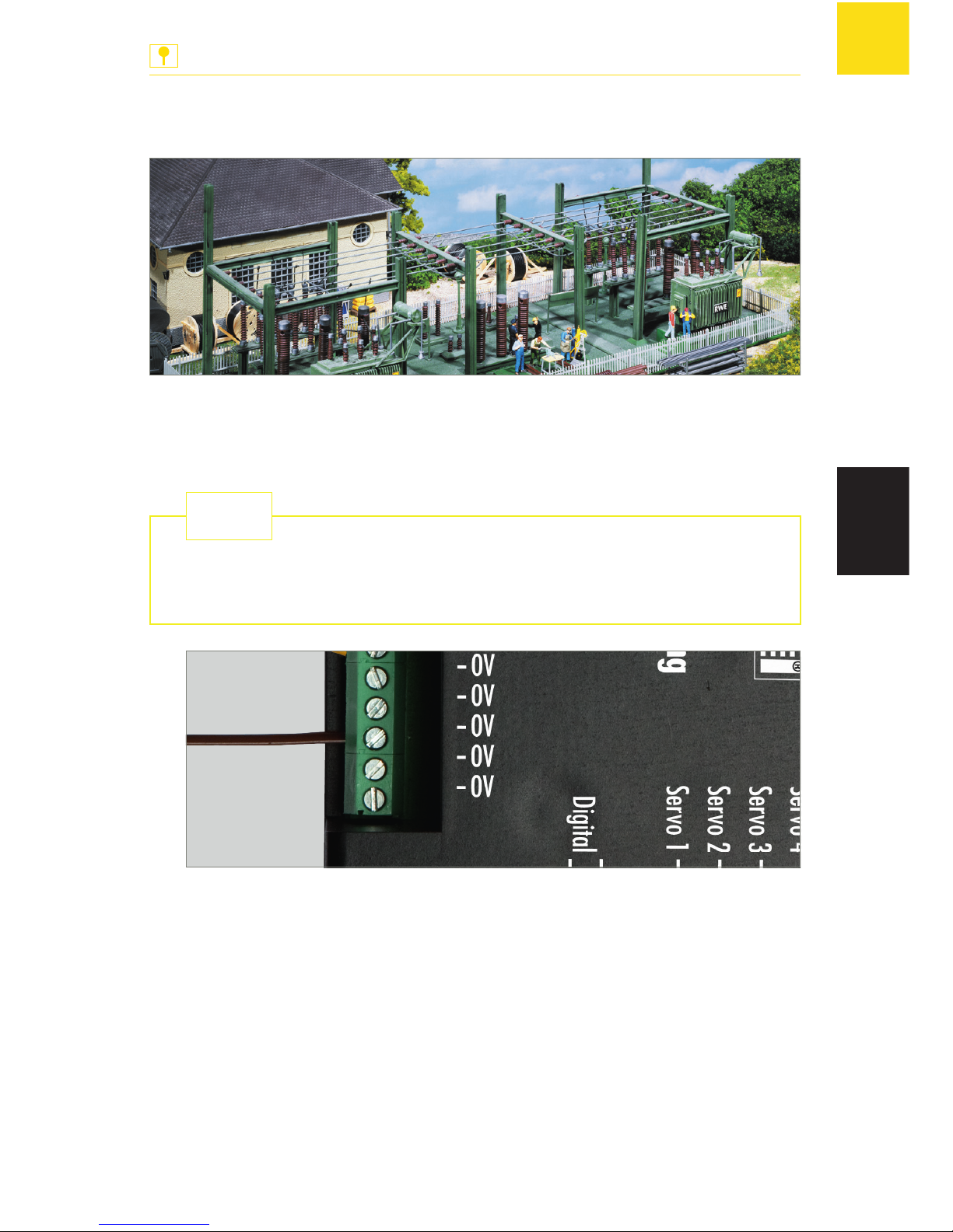
Fig. 2: Connecting to the ground
X
Connect a wire, which is itself connected to the ground, to one of the
»0V« ports of the Servo Control, see Fig. 2.
Page 36
36
Connection
ANLAGENBAU
EN
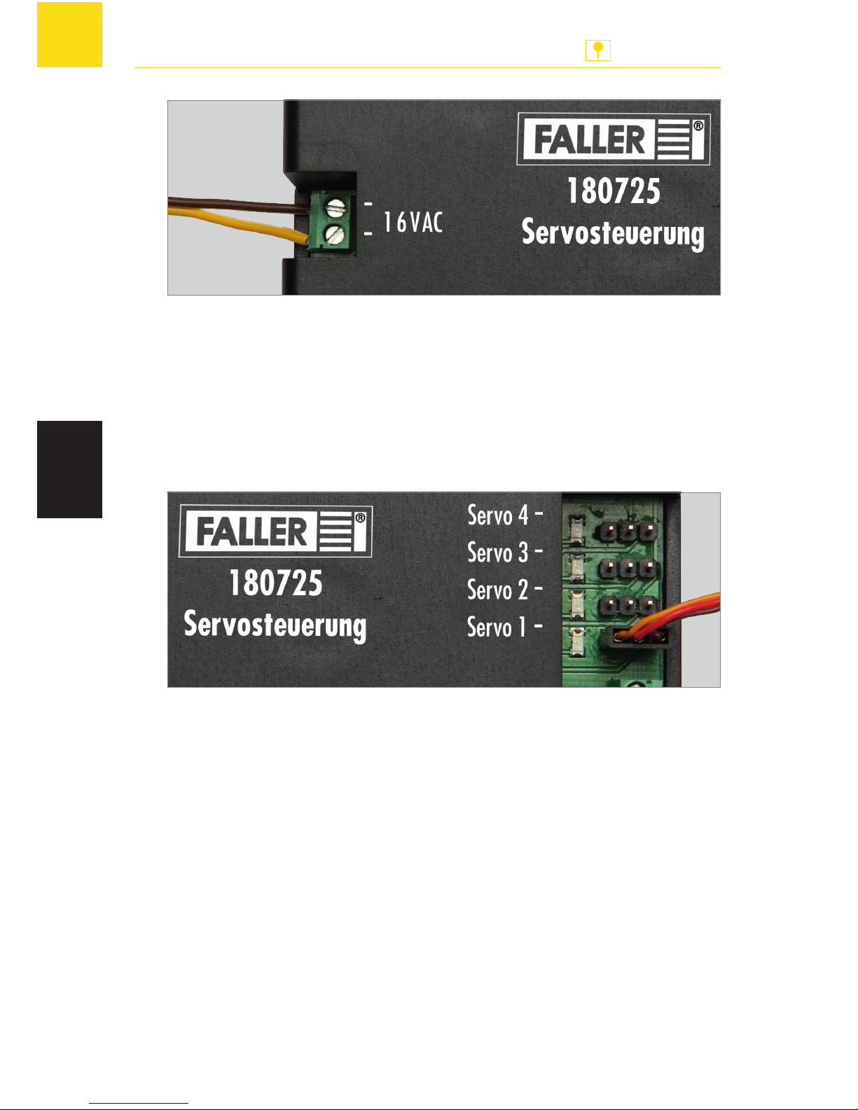
Fig. 3: Connecting the supply voltage
X
Connect a 16 V alternating voltage to the »16 VAC« port of the Servo
Control, see Fig. 3.
»Prog« LED flashes at lower heart rate.
Connecting servos
You may connect up to four servos to the Servo Control.
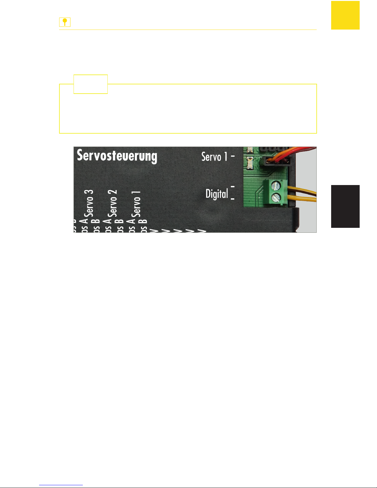
Fig. 4: Connecting servos
ADVICE: »Servo 1« to »Servo 4« ports are protected against reversed polarity. If you have wrongly connected the supply cable of a servo by mistake,
the Servo Control will not be able to address the servo. In such a case simply rotate the plug by 180°.
X
Connect one or several servos to one or several of the »Servo 1« to
»Servo 4« ports on the Servo Control, see Fig. 4.
Page 37
37
Connection
ANLAGENBAU
EN
Connecting a digital control unit
The Servo Control is compatible with DCC and Motorola digital systems.
If you connect the Servo Control to a digital control unit, you will be
able to preset the servos effortlessly via the digital control unit even
though the Servo Control has been built into your installation already.
TIP
Fig. 5: Connecting a digital control unit
ADVICE: A digital control unit and the Servo Control may not under any
circumstances be connected to the same transformer.
X
If you want to preset servos via a digital control unit, connect the »Dig-
ital« port of the Servo Control to a programming track port of the digital control unit, see Fig. 5.
X
If you want to position servos via a digital control unit, connect the
»Digital« port of the Servo Control to a track output of a digital control unit, see Fig. 5.
Page 38
38
Connection
ANLAGENBAU
EN
Connecting push buttons
For each servo position you may connect a push button.
Fig. 6: Connecting push buttons
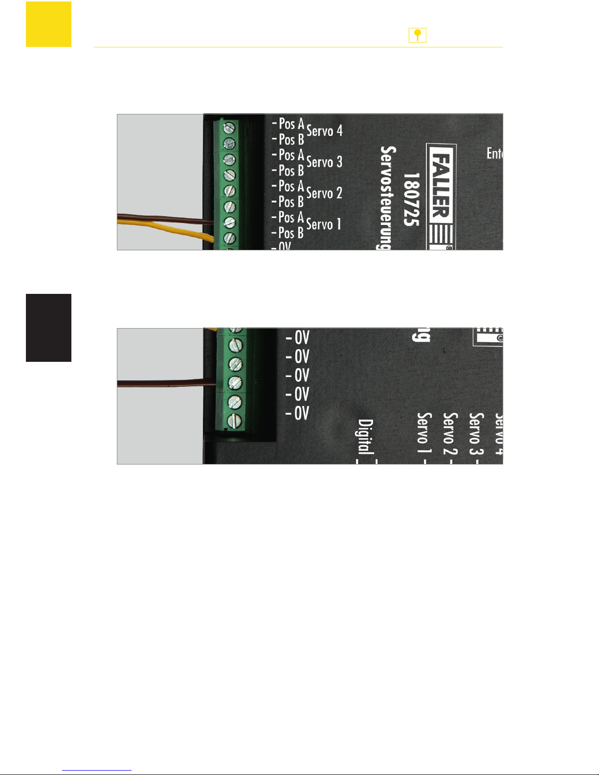
X
Connect one or several push buttons to one or several of the »Pos A
Servo 1« to »Pos A Servo 4« ports and »Pos B Servo 1« to »Pos B Servo
4« ports on the Servo Control, see Fig. 6.
Fig. 7: Connecting to the ground
X
For each push button, connect the ground wire of the push button to
one of the »0V« ports on the Servo Control, see Fig. 7.
Page 39
39
Presetting servos
ANLAGENBAU
EN
5. Presetting servos
The Servo Control allows you to preset servos in three different ways:
Presetting servos via the Servo Control
Presetting servos via a digital control unit
Presetting servos via configuration variables (CV)
Presetting servos via the Servo Control
Servos are preset directly via the keys on the Servo Control. On doing so,
you are able to preset both hold positions of the first address and the motion
rate of the servo.
In programming mode the unit will always go through the following possible presettings one after the other:
Programming path analog or digital
Connecting the required servo
First hold position of the servo
Second hold position of the servo
Motion rate of the servo
ADVICE: During the entire programming procedure you may leave the programming mode by pressing the »Prog« key. The settings you have performed up to that moment will not be saved.
Prerequisite conditions:
The Servo Control is connected to the supply voltage.
A servo is connected to the Servo Control.
X
Press the »Prog« key.
»Prog« LED lights up. The programming mode is activated.
Page 40

40
Presetting servos
ANLAGENBAU
EN
X
Press the »+« key.
The analog programming path is activated.
»Servo 1« LED lights up.
X
Using the »+« and »-« keys, select the port of the servo that you want
to preset.
ADVICE: If the servo does not move after the next step, this means that polarity is reversed at the connector. In such a case simply rotate the plug by 180°.
X
Press the »Enter« key.
The servo connected to the selected port briefly moves.
X
Using the »+« and »-« keys, preset the first hold position of the servo
(hold position “red”). By keeping the keys pressed, you will also be able
to perform large changes of position easily.
X
Press the »Enter« key.
The servo moves to the second hold position.
X
Using the »+« and »-« keys, preset the second hold position of the servo
(hold position“green”). By keeping the keys pressed, you will also be
able to perform large changes of position easily.
X
Press the »Enter« key.
The servo moves to and fro between both preset hold positions.
X
Using the »+« and »-« keys, preset the motion rate of the servo.
X
Press the »Enter« key.
The settings are saved.
The LED of the programmed servo port goes out.
»Prog« LED flashes at lower heart rate.
Page 41
41
Presetting servos
ANLAGENBAU
EN
Presetting servos via a digital control unit
The servos are preset via a digital control unit. On doing so, you are able to
preset both hold positions of the first address and the motion rate of the servo.
In programming mode the unit will always go through the following possible presettings one after the other:
Analog or digital programming path
DCC or Motorola data format
Connecting the required servo
Control keys on the digital control unit
Temporary presetting keys »+« and »-« on the digital control unit
First hold position of the servo
Second hold position of the servo
Motion rate of the servo
Alternatively, presettings can also be performed using another control device that allows to switch coil items. To this end, you have to
specify, during the programming procedure, two keys that will be
used by the Servo Control only when programming the servos. You
may use any two coil item keys that will serve as »+« and »-« keys
during programming. When the programming procedure is completed, the Servo Control will delete that setting and it will be possible to use the keys again for points or signals.
TIP
ADVICES:
During the entire programming procedure you may leave the program-
ming mode by pressing the »Prog« key. The settings you have performed
up to that moment will not be saved.
If you select the wrong data format, the Servo Control will not react to
any key input on the digital control unit.
Prerequisite conditions:
The Servo Control is connected to the supply voltage.
The Servo Control is connected to a programming track port of a digital
control unit.
A servo is connected to the Servo Control.
Page 42

42
Presetting servos
ANLAGENBAU
EN
X
Press the »Prog« key.
»Prog« LED lights up. The programming mode is activated.
X
Press the »-« key.
The digital programming path is activated.
»Servo 1« and »Servo 2« LEDs are flashing.
X
Using the »+« and »-« keys, select the required data format.
When »Servo 1« and »Servo 2« LEDs are flashing , the DCC data for-
mat has been selected.
When »Servo 3« and »Servo 4« LEDs are flashing, the Motorola data
format is selected.
X
Press the »Enter« key.
»Servo 1« LED lights up.
X
Using the »+« and »-« keys, select the port of the servo that you want
to preset.
X
Press the »Enter« key.
ADVICE: If the servo does not move after the next step, this means that polarity is reversed at the connector. In such a case simply rotate the plug by 180°.
X
On the digital control unit press one of the two keys of a coil item address
that is intended to move the servo later on.
The servo briefly moves.
You have specified the control keys on the digital control unit.
ADVICE: The keys that have to serve as temporary »+« and »-« keys during
the programming procedure may not under any circumstances be identical
with the control keys you have selected previously. Select for each temporary »+« and »-« key a particular coil item address.
X
On the digital control unit press the key that will have to serve as temporary »+« key during the programming procedure.
The servo briefly moves.
X
On the digital control unit press the key that will have to serve as temporary »-« key during the programming procedure.
The servo briefly moves.
X
Using a control key on the digital control unit, set the servo to its first
hold position (hold position “red” for instance).
X
Using the temporary »+« and »-« keys on the digital control unit, preset the first hold position of the servo (hold position “red”).
Page 43

43
Presetting servos
ANLAGENBAU
EN
X
Using the other control key on the digital control unit, set the servo to
its second hold position (hold position “green”).
X
Using the temporary »+« and »-« keys on the digital control unit, preset
the second hold position of the servo (hold position “green”).
X
Save both hold positions of the servo by moving to and fro three times
between the hold positions by means of the control keys, without changing the presettings.
The servo moves to and fro between both preset hold positions.
X
Using the temporary »+« and »-« keys on the digital control unit, preset the motion rate of the servo.
X
Press on one of the two control keys.
The presettings are saved.
The LED of the programmed servo port goes out.
»Prog« LED flashes at lower heart rate.
Page 44
44
Presetting servos
ANLAGENBAU
EN
Presetting servos via configuration variables (CV)
The servos are preset by means of configuration variables (CV) via a digital control unit that can handle the DCC data format. On doing so, you are
able to preset both hold positions of the first address and the motion rates
of the servo as well as the rocking function.
Via a second address you are also able to preset two additional hold positions independently of each other. You will thus be able to place for instance
swivel water spouts in four different hold positions.
NOTICE
Property damage will result from wrong settings or wrong programming.
The Servo Control and the servos might no longer function properly or
be destroyed.
X
Only program if you have a working knowledge of programming CVs.
X
Read through and follow the directions given in the instruction manual of the digital control unit.
Prerequisite conditions:
The Servo Control is connected to the supply voltage.
The Servo Control is connected to a programming track port of a digital
control unit that can handle the DCC data format.
A servo is connected to the Servo Control.
ADVICE: Please refer to the operating instructions of the digital control unit
to find how to program that digital control unit.
X
On the digital control unit select the function by means of which you
can preset configuration variables.
X
Preset the relevant configuration variables on the digital control unit.
To this end, use the table „Synopsis of all configuration variables“ on
page 46 as well as paragraph „Example: Presetting the rocking function“ on page 45.
X
Transfer the preset values to the Servo Control.
The presettings are saved.
Page 45
45
Presetting servos
ANLAGENBAU
EN
Example: Presetting the rocking function
The present example makes use of the rocking function to show how it is
possible to preset servos via configuration variables. You will be able to perform other presettings on the servos by following the same principle.
The rocking function allows you to add to barriers or gates that are
moved using servos a rocking motion during the opening and shutting
procedure, which will impart them a very realistic motion. Whenever a
servo reaches a hold position, it will subsequently perform cyclic dampened oscillations. The rocking motion can be adjusted via the rocking
time and the amplitude of oscillation.
TIP
ADVICES:
Whenever you use the rocking function, the servo will only be able to
go to the hold positions of the first address. It can no longer go to the
hold positions of the second address.
If you set the CV of the rocking amplitude to the values 0 or 127 (mini-
mum and maximum values), the rocking function will not be performed.
In the present example we assume that a servo has been connected to
the »Servo 1« port of the Servo Control.
X
On the digital control unit select the function by means of which you
can preset configuration variables.
X
Using CV no. 122 preset the first hold position of the servo (hold position “red”), giving it the value “40” for instance.
X
Using CV no. 123 preset the second hold position of the servo (hold
position “green”), giving it the value “100” for instance.
X
Using CV no. 125 preset the amplitude of oscillation of the first hold position of the servo (hold position “red”), giving it the value “35” for instance.
X
Using CV no. 126 preset the rocking time of the first hold position of
the servo (hold position “red”), giving it the value “90” for instance.
X
Using CV no. 127 preset the amplitude of oscillation of the second hold position of the servo (hold position “green”), giving it the value “70” for instance.
X
Using CV no. 128 preset the rocking time of the second hold position of
the servo (hold position “green”), giving it the value “125” for instance.
X
Transfer the values so preset to the Servo Control.
The presettings are saved.
Page 46
46
Presetting servos
ANLAGENBAU
EN
Synopsis of all configuration variables
CV Description Range Default
setting
112 Software version - varying
113 Manufacturer’s code (Manufacture ID) - 85
119 Decoder configuration 0-15 15
Bit0 = 1: Voltage at output 1 is
always switched on
Bit0 = 0: Voltage at output 1 is
switched on only when
servo is in motion
Bit1 = 1: Voltage at output 2 is
always switched on
Bit1 = 0: Voltage at output 2 is
switched on only when
servo is in motion
Bit2 = 1: Voltage at output 3 is
always switched on
Bit2 = 0: Voltage at output 3 is
switched on only when
servo is in motion
Bit3 = 1: Voltage at output 4 is
always switched on
Bit3 = 0: Voltage at output 4 is
switched on only when
servo is in motion
Bit4: Is not used
Bit5: Is not used
Bit7 = 0: DCC operation
Bit7 = 1: Motorola operation
Page 47
47
Presetting servos
ANLAGENBAU
EN
CV Description Range Default
setting
»Servo 1« port
120 HighByte Address 1 0-8 0
121 LowByte Address 1 0-255 1*
122 Hold position “red” Address 1 0-127 30
123 Hold position “green” Address 1 0-127 95
124 Positioning time 0-255 40
125 Rocking amplitude Hold position “red”
Address 1
0-127 0
126 Rocking time Hold position “red” Address 1 0-255 0
127 Rocking amplitude Hold position “green”
Address 1
0-127 0
128 Rocking time Hold position “green”
Address 1
0-255 0
160 HighByte Address 2 0-8 0
161 LowByte Address 2 0-255 0
162 Hold position “red” Address 2 0-127 0
163 Hold position “green” Address 2 0-127 0
»Servo 2« port
130 HighByte Address 1 0-8 0
131 LowByte Address 1 0-255 3*
132 Hold position “red” Address 1 0-127 30
133 Hold position “green” Address 1 0-127 95
134 Positioning time 0-255 40
135 Rocking amplitude Hold position “red”
Address 1
0-127 0
136 Rocking time Hold position “red” Address 1 0-255 0
137 Rocking amplitude Hold position “green”
Address 1
0-127 0
Page 48
48
Presetting servos
ANLAGENBAU
EN
CV Description Range Default
setting
138 Rocking time Hold position “green”
Address 1
0-255 0
170 HighByte Address 2 0-8 0
171 LowByte Address 2 0-255 0
172 Hold position “red” Address 2 0-127 0
173 Hold position “green” Address 2 0-127 0
»Servo 3« port
140 HighByte Address 1 0-8 0
141 LowByte Address 1 0-255 5*
142 Hold position “red” Address 1 0-127 30
143 Hold position “green” Address 1 0-127 95
144 Positioning time 0-255 40
145 Rocking amplitude Hold position “red”
Address 1
0-127 0
146 Rocking time Hold position “red” Address 1 0-255 0
147 Rocking amplitude Hold position “green”
Address 1
0-127 0
148 Rocking time Hold position “green”
Address 1
0-255 0
180 HighByte Address 2 0-8 0
181 LowByte Address 2 0-255 0
182 Hold position “red” Address 2 0-127 0
183 Hold position “green” Address 2 0-127 0
»Servo 4« port
150 HighByte Address 1 0-8 0
151 LowByte Address 1 0-255 7*
152 Hold position “red” Address 1 0-127 30
Page 49
49
Presetting servos
ANLAGENBAU
EN
CV Description Range Default
setting
153 Hold position “green” Address 1 0-127 95
154 Positioning time 0-255 40
155 Rocking amplitude Hold position “red”
Address 1
0-127 0
156 Rocking time Hold position “red” Address 1 0-255 0
157 Rocking amplitude Hold position “green”
Address 1
0-127 0
158 Rocking time Hold position “green”
Address 1
0-255 0
190 HighByte Address 2 0-8 0
191 LowByte Address 2 0-255 0
192 Hold position “red” Address 2 0-127 0
193 Hold position “green” Address 2 0-127 0
Tab. 1: Synopsis of all configuration variables (CV).
* ADVICE: If you use a Motorola digital control unit, default settings for the
addresses of configuration variables 121, 131, 141 and 151 are not available.
Page 50
50
Positioning servos
ANLAGENBAU
EN
6. Positioning servos
The Servo Control allows you to position servos in two different ways:
Positioning servos via the Servo Control
Positioning servos via a digital control unit
Positioning servos via the Servo Control
Servos that are connected to the Servo Control can be positioned via the
Servo Control.
Prerequisite conditions:
The Servo Control is connected to the supply voltage.
A servo is connected to the Servo Control.
For each servo position a push button is connected to the Servo Control.
The servo has been preset.
X
Press a push button that is connected to the Servo Control.
Positioning servos via a digital control unit
A servo can easily be positioned via a digital control unit.
Prerequisite conditions:
The Servo Control is connected to the supply voltage.
The Servo Control is connected to a track output of a digital control unit.
A servo is connected to the Servo Control.
That servo has been preset via the digital control unit.
X
Press a control key you have programmed when presetting the servo
via the digital control unit, see Chapter „Presetting servos via a digital
control unit“, page 41.
Page 51
51
How to deal with problems
ANLAGENBAU
EN
7. How to deal with problems
Direct line to FALLER’s customer service department:
Phone + 49 (0) 77 23 / 651-106
E-mail [email protected]
TIP
Problem Possible cause Remedy
A servo
does not
work.
The Servo Control is
not connected to the
supply voltage.
X
Connect 16 V alternating
voltage to the »16 VAC«
port of the Servo Control.
Polarity of the connector of the servo has
been reversed.
X
Rotate the plug of the servo
by 180°.
The rocking function does
not work.
The configuration variable of the amplitude of oscillation has
be given the value 0
or 127 (minimum and
maximum values). This
makes the servo unable to carry out the
rocking motion.
X
Give a value that is higher
than 0 and lower than 127.
Tab. 2: How to deal with problems
Page 52
52
Interesting facts
ANLAGENBAU
EN
8. Interesting facts
Servos
What is a servo?
A servo is a device that is able to transform control commands into mechanical motions.
Types
In model making we speak of analog and digital servos. In an analog servo
the electronic equipment features an analog structure. In a digital servo the
position of the motor is detected in the form of a numerical value and compared with a desired value by an appropriate computing circuit. Digital servos feature a higher angular resolution and their position is adjusted more
quickly and more accurately. Digital servos can often be reprogrammed,
which allows to adapt the speed, the overload protection and similar to the
specific application, depending on the servo version. However, the auxiliary energy required by digital servos as well as their price are higher than
those of analog servos.
Structure
A servo is composed of a drive unit and a triggering unit such as for instance
an electric motor with electronic control system. The motor must be able
to rotate in both directions, and the system must be able to determine the
rotating position of the motor at any moment. The electric connection of a
servo is carried out using three wires. Two for the operating voltage (“plus”
and “minus”) and one for the pulse (“Desired value”).
Page 53

53
Interesting facts
ANLAGENBAU
EN
Mode of operation
Servos – in particular model making servos – are addressed using pulse-width
modulation. On servos pulse-width modulation is also called pulse-pause
modulation. The pulse width then represents the desired value. That value is
cyclically repeated, every 20 ms on most servos, and must lie between 1ms
(at the very left) and 2 ms (at the very right). However, the resolution as well
as the specific time values vary in most cases from servo to servo. Many servos – in particular digital servos – also allow operation beyond the 1ms to
2 ms range. Then angular variations up to approximately 180 degrees may
be obtained by way of exception.
To allow the accurate detection of the motor position each servo is fitted
with a measuring device that determines the current position of the motor,
e.g. the angle of rotation travelled with regard to an initial position. Such
measurement is carried out via an angular motion transducer, e.g. a synchro resolver, an incremental transducer or an absolute value transducer.
An electronic regulation circuit compares the signal emitted by the angular
motion transducer with the specified desired value. If a deviation is detected,
the motor is rotated in the direction ensuring the shortest way towards the
desired value. This results in the deviation getting smaller. The procedure is
repeated by increments of approximations until the actual value lies within
the tolerance limit of the desired value. Such positioning procedure represents the simplest case. Alternatively, that principle also allows to regulate
torque or velocity values. Which makes for instance uniform driving profiles
under varying loads possible.
Do you want to find out more about the subject? Quench your thirst
for knowledge on our homepage – www.faller.de. You will find there
some interesting background information and a lot of creative suggestions for all areas of model making.
TIP
Page 54
54
Technical data and symbols
ANLAGENBAU
EN
9. Technical data and symbols
Power supply
Designation Value
Supply voltage 16 V alternating current
Frequency range 50/60 Hz
Total load 700 mA
Load on each servo output 700 mA
Approved servos All commercially available
standard servos
Number of connectable servos 4 servos
Tab. 3: Power supply
Digital data
Designation Value
Switching addresses 2 switching addresses
Address range 1-2048
Pulse-width of control pulses
emitted by the digital control unit
Between 1 and 2 ms
Digital formats DCC
Motorola
Tab. 4: Digital Data
Page 55
55
Technical data and symbols
ANLAGENBAU
EN
Symbols
Symbol Meaning
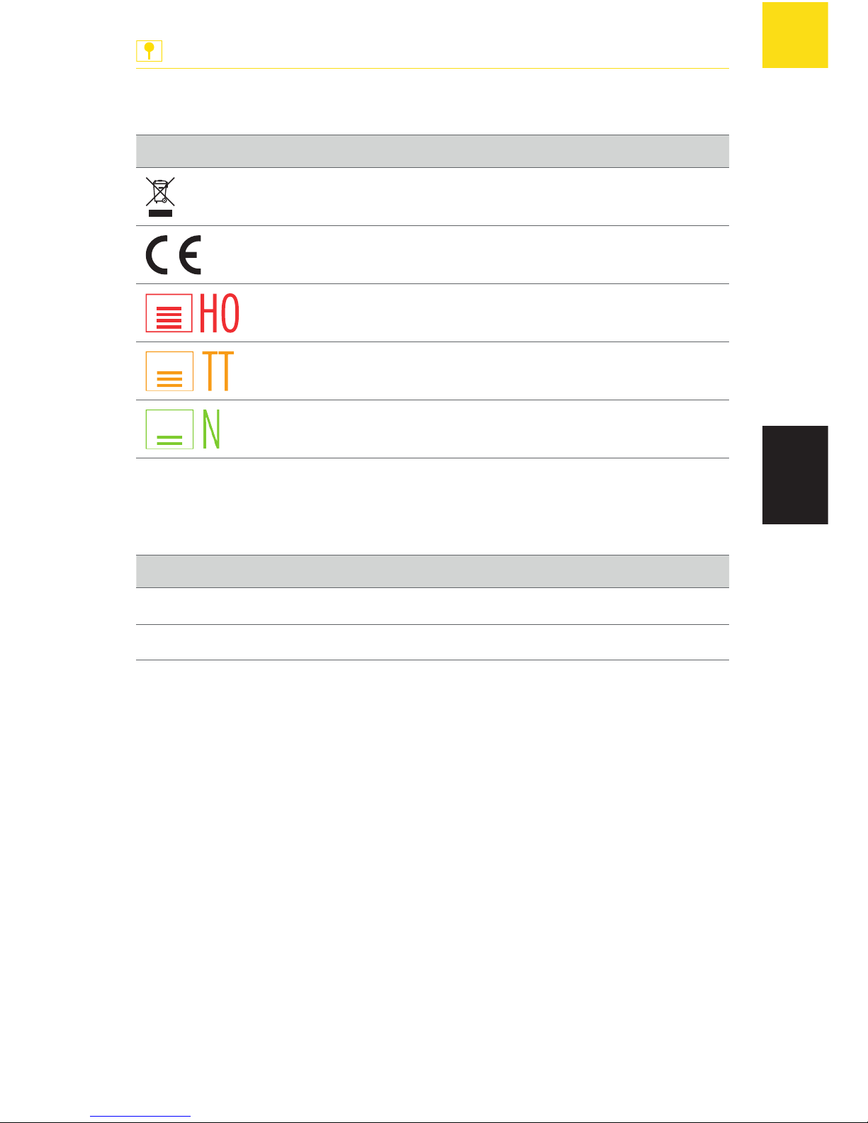
Product subject to the 2002/96/EC
European Directive
CE conformity label
1:87/H0/16.5 mm track gauge
1:120/TT/12 mm track gauge
1:160/N/9 mm track gauge
Tab. 5: Symbole
Signs
Sign Meaning
X
Action
g
Note
Tab. 6: Signs
Page 56
© Gebr. FALLER GmbH | Sachnr. 180 725 1 | Änderungen vorbehalten | 19.09.2012
Gebr. FALLER GmbH
Kreuzstraße 9
78148 Gütenbach
Telefon +49 (0) 77 23 / 651-0
Telefax +49 (0) 77 23 / 651-123
www.faller.de
[email protected]
 Loading...