

Page 1
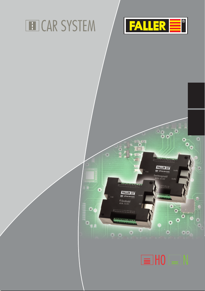
161351/161352
PC-Grundmodul/Erweiterungsmodul
DE
161351/161352
PC-standard module/
Expansion module
Bedienungsanleitung
Instruction Manual
EN
Page 2
DE
Inhalt
1. FALLER Car System – Jetzt wird’s digital ........................................... 3
2. Sicherheit und Verantwortung ..........................................................4
Bestimmungsgemäßer Gebrauch ...................................................... 4
Zu Ihrer Sicherheit ............................................................................ 4
Umweltgerecht entsorgen ................................................................ 5
3. Produktübersicht .............................................................................. 6
Lieferumfang ................................................................................... 6
Bestandteile des PC-Grundmoduls ................................................... 7
Bestandteile des Erweiterungsmoduls ............................................... 8
4. Grund- und Erweiterungsmodul anschließen .................................... 9
Stromversorgung anschließen .......................................................... 9
Rückmeldekontakte anschließen .................................................... 10
Funktionselemente anschließen ...................................................... 11
PC-Verbindung herstellen ..............................................................13
Weitere LocoNet-Module anschließen............................................14
5. Treiber- und Softwareinstallation .................................................... 16
Systemvoraussetzungen ................................................................. 16
Software installieren ....................................................................... 16
6. Die Software »Car System 2« ......................................................... 17
Das Anwendungsfenster ................................................................ 18
Module hinzufügen........................................................................ 18
Module entfernen .......................................................................... 19
Einstellungen.................................................................................. 19
Eingänge konfigurieren .................................................................. 20
Ausgänge konfigurieren ................................................................. 21
Stopp-Stelle, Parkplatz, Abzweigung, Schaltausgang ...................... 22
Ampelschaltung ............................................................................. 23
7. Technische Daten und Symbole ...................................................... 24
2
Page 3
FALLER Car System – Jetzt wird’s digital
1. FALLER Car System – Jetzt wird’s digital
Herzlichen Glückwunsch – Sie sind fündig geworden!
Mit den Steuerungsmodulen aus der FALLER Digital-Serie haben Sie ab
sofort die Möglichkeit Ihre Funktionselemente auf der Modellanlage über
eine Digitalzentrale oder einen PC zu steuern.
Das PC-Grundmodul verfügt über 11 Eingänge und 12 Ausgänge sowie ein
USB Interface, welches den Anschluss an einen PC ermöglicht. Das Modul
ist mit einer LocoNet-Schnittstelle ausgerüstet, an der beliebig viele weitere,
verschiedene LocoNet-Module angeschlossen werden können.
Mit jedem Erweiterungsmodul kommen 11 Eingänge und 12 Ausgänge dazu.
Die Software »Car System 2« ermöglicht die einfache Konfiguration der
Module über einen PC.
Nicht zuletzt erhalten Sie mit der dem PC-Grundmodul beiliegenden Demo-
Version von »Win-Digipet« Zugang zur automatischen Steuerung von
Modellanlagen mit einem PC.
Viele kreative Ideen und viel Freude mit Ihrem Produkt wünscht Ihnen Ihre
Gebr. FALLER GmbH!
DE
3
Page 4
Sicherheit und Verantwortung
2. Sicherheit und Verantwortung
DE
Bestimmungsgemäßer Gebrauch
Dieses Produkt ist ein Modellbauartikel für anspruchsvolle Modellbauer und
Sammler und kein Spielzeug. Das Produkt ist dazu bestimmt, im Rahmen
einer Modellanlage eingesetzt zu werden. Es darf ausschließlich mit den von
FALLER dafür empfohlenen Zubehörartikeln bzw. Anbauten betrieben werden. FALLER-Produkte sind grundsätzlich für den Hobbygebrauch konzipiert
und konstruiert, nicht für den Dauerbetrieb. Das Produkt ist dazu bestimmt,
bei durchschnittlicher Raumtemperatur und Luftfeuchte eingesetzt zu werden. Verwenden Sie das Produkt nur im Innenbereich und vermeiden Sie
Witterungseinflüsse. Jede andere Verwendung gilt als nicht bestimmungsgemäß. Für Schäden oder Mängel, die hierdurch oder durch Nichtbeachtung
der Bedienungsanleitung oder der beiliegenden Sicherheitshinweise entstehen, übernimmt die Gebr. FALLER GmbH keine Haftung.
Betriebs- und Lagerbedingungen
X
Halten Sie folgende Betriebsbedingungen ein: 15 °C - 40 °C, bis 75 %
rel. Luftfeuchte, Betauung unzulässig.
X
Halten Sie folgende Lagerbedingungen ein: 10°C - 60°C, bis 85 % rel.
Luftfeuchte, Betauung unzulässig.
Zu Ihrer Sicherheit
X
Lesen Sie die Bedienungsanleitung und die beiliegenden Sicherheitshinweise sorgfältig vor Gebrauch.
X
Beachten Sie die Sicherheitshinweise und Warnungen in der Bedienungsanleitung, in den beiliegenden Sicherheitshinweisen und am Produkt.
4
Page 5

Sicherheit und Verantwortung
X
Halten Sie die Bedienungsanleitung und die beiliegenden Sicherheitshinweise beim Produkt verfügbar.
X
Geben Sie das Produkt nur zusammen mit der Bedienungsanleitung und
mit den beiliegenden Sicherheitshinweisen an Dritte weiter.
WEEE-Hinweis (Umweltgerecht entsorgen)
Produkte, die mit einem durchgestrichenen Mülleimer-Symbol gekennzeichnet sind, dürfen am Ende ihrer Lebensdauer nicht über den normalen Haushaltsabfall entsorgt werden, sondern müssen an einem Sammelpunkt für das
Recycling von elektrischen und elektronischen Geräten abgegeben werden.
Das Symbol auf dem Produkt, der Gebrauchsanleitung oder der Verpackung
weist darauf hin. Die Wertstoffe sind gemäß ihrer Kennzeichnung wiederverwertbar. Mit der Wiederverwendung, der stofflichen Verwertung oder
anderen Formen der Verwertung von Altgeräten leisten Sie einen wichtigen
Beitrag zum Schutze unserer Umwelt. Bitte erfragen Sie bei Ihrer Gemeindeverwaltung die zuständige Entsorgungsstelle.
X
Beachten Sie die örtlichen Bestimmungen zur Abfallbeseitigung.
X
Beachten Sie die WEEE-Richtlinie in ihrer derzeit aktuellen Fassung.
X
Trennen Sie bei einer Entnahme von Batterien oder Akkus das Produkt
von der Spannungsversorgung.
X
Entnehmen Sie vor einer Verschrottung des Produkts ggf. enthaltene
Batterien oder Akkus.
Hinweis gemäß BattG (Batteriegesetz)
Batterien und Akkus dürfen nicht im Hausmüll entsorgt werden, sondern
Sie sind zur Rückgabe gebrauchter Batterien und Akkus an einer kommunalen Sammelstelle oder im Handel vor Ort gesetzlich verpflichtet. Altbatterien können Schadstoffe enthalten, die bei nicht sachgemäßer Lagerung
oder Entsorgung die Umwelt oder Ihre Gesundheit schädigen können. Batterien enthalten aber auch wichtige Rohstoffe, wie z.B. Eisen, Zink, Mangan oder Nickel und können verwertet werden. Sie können die Batterien
nach Gebrauch entweder an uns zurücksenden oder in unmittelbarer Nähe
(z.B. im Handel oder in kommunalen Sammelstellen) unentgeltlich zurückgeben. Die Abgabe in Verkaufsstellen ist dabei für Endnutzer auf die üblichen Mengen sowie solche Altbatterien beschränkt, die der Vertreiber als
Neubatterien in seinem Sortiment führt oder geführt hat. Das Zeichen mit
der durchgestrichenen Mülltonne bedeutet, dass Batterien und Akkus nicht
im Hausmüll entsorgt werden dürfen.
X
Entsorgen Sie die Batterien und Akkus bei den dafür zuständigen und
staatlich bestimmten Stellen.
DE
5
Page 6
Produktübersicht
3. Produktübersicht
DE
Lieferumfang
PC-Grundmodul (nur in Artikel 161351)
Erweiterungsmodul (nur in Artikel 161352)
CD-ROM (nur in Artikel 161351)
Anleitung
6
Page 7
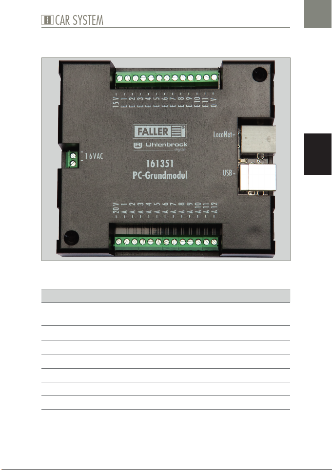
Bestandteile des PC-Grundmoduls
Abb. 1: PC-Grundmodul
Anschlüsse Beschreibung
»16 VAC« Anschluss für die Spannungsversorgung
(16 V Wechselspannung)
»USB« USB PC-Anschluss
»LocoNet« LocoNet Schnittstelle
»E 1 - E 11« 11 Eingänge
»0 V« 0 V für Eingänge
»A 1 - A 12« 12 Ausgänge
»15 V« 15 V für Ausgänge
»20 V« 20 V für Ausgänge
Produktübersicht
DE
7
Page 8
DE
Produktübersicht
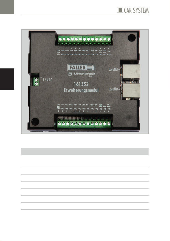
Bestandteile des Erweiterungsmoduls
Abb. 2: Erweiterungsmodul
Anschlüsse Beschreibung
»16 VAC« Anschluss für die Spannungsversorgung
(16 V Wechselspannung)
»LocoNet« LocoNet Schnittstelle
»E 1 - E 11« 11 Eingänge
»0 V« 0 V für Eingänge
»A 1 - A 12« 12 Ausgänge
»15 V« 15 V für Ausgänge
»20 V« 20 V für Ausgänge
8
Page 9
Grund- und Erweiterungsmodul anschließen
4. Grund- und Erweiterungsmodul anschließen
Stromversorgung anschließen
Die Module werden mit 16 V Wechselspannung betrieben.
TIPP
Die notwendige Wechselspannung können Sie zum Beispiel mit dem
FALLER Transformator 50 VA, 50-60 Hz, Artikelnummer 180641,
erzeugen.
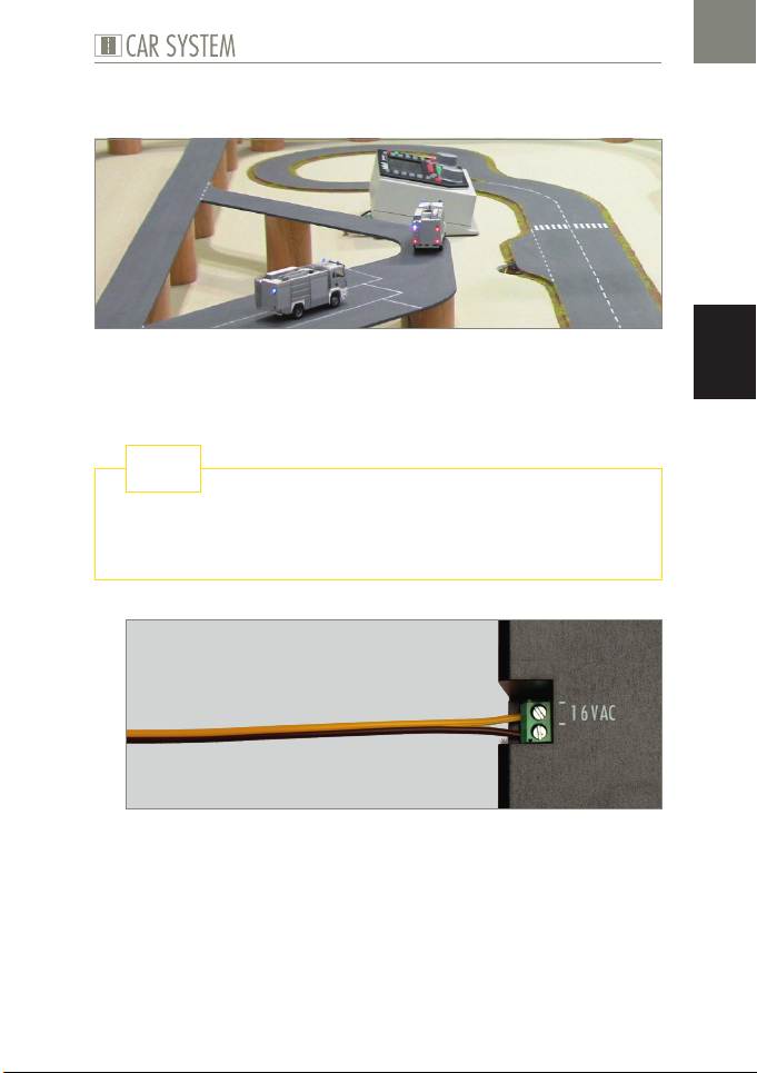
Abb. 3: Anschlussseite
X
Schließen Sie die Module an 16 V Wechselspannung an, siehe Abb. 3.
DE
9
Page 10
DE
Grund- und Erweiterungsmodul anschließen
Rückmeldekontakte anschließen
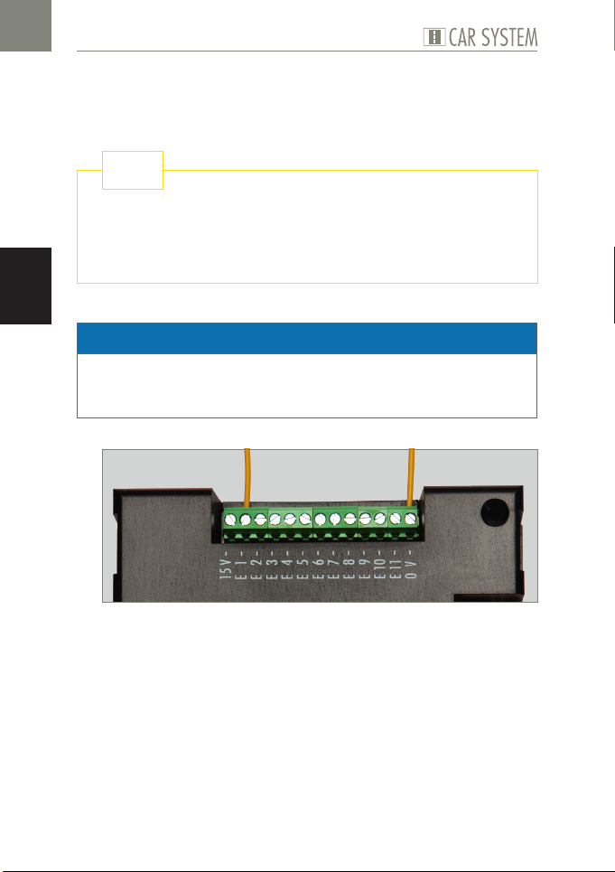
Die Eingänge der Module müssen alle »potentialfrei« geschaltet werden.
TIPP
Hier können Taster, Sensoren, Schaltgleise oder die potentialfreien
Ausgänge von Schaltdecodern angeschlossen werden. Für die Rückmeldung aus der Straße verwenden Sie FALLER-Sensoren, Artikelnummer 161773.
ACHTUNG
Schließen Sie niemals spannungsführende Komponenten, wie z.B. die Ausgänge eines Weichendecoders, an den Eingängen der Module an. Dies
kann zur Zerstörung der Module führen.
Abb. 4: Rückmeldekontakte
X
Schließen Sie ein Ende des Sensors an Masse (0 V) und das andere am
gewünschten Eingang an (E1 - E11), siehe Abb. 4.
10
Page 11
Grund- und Erweiterungsmodul anschließen
TIPP
Wollen Sie noch mehr wissen? Stillen Sie Ihren Wissensdurst auf
unserer Internetseite www.faller.de. Dort finden Sie interessante Hin-
tergrundinformationen und viele kreative Anregungen rund um das
Thema Modellbau.
Funktionselemente anschließen
Über die Ausgänge der Module können verschiedene Verbraucher gesteuert werden. Dies können zum einen die Funktionselemente von FALLER Car
System (Abzweigung, Parkplatz und Stopp-Stelle) sein oder andere Verbraucher wie LED oder Lampen.
Hinweise:
Achten Sie beim Anschluss von LED immer auf die korrekten Vorwi-
derstände. Diese können Sie in der Software »Car System 2« über den
Menüpunkt Allgemein >> Vorwiderstandsrechner ermitteln.
Schließen Sie Parkplatz und Stopp-Stelle an 20 V an. Schließen Sie im
Unterschied dazu Abzweigung und Beleuchtungselemente an 15 V an.
Achten Sie beim Anschluss der Stopp-Stelle auf die korrekte Polung. Soll
ein Fahrzeug an dieser Stelle anhalten, muss der Nordpol nach oben weisen. Testen Sie dies, indem Sie den Lenkschleifer über das Zentrum der
eingeschalteten Stopp-Stelle bewegen. Wird der Lenkschleifer abgestoßen, ist der Nordpol oben. Soll dagegen ein Fahrzeug der FALLER Digitalserie an dieser Stelle seine zweite Fahrstufe abrufen, muss der Südpol
nach oben weisen.
DE
TIPP
Weitere Informationen zum Anschluss der Verbraucher entnehmen
Sie bitte der Bedienungsanleitung des jeweiligen Geräts.
11
Page 12
DE
Grund- und Erweiterungsmodul anschließen
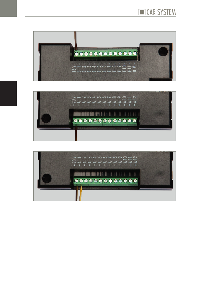
Abb. 5: Schraubklemme 15 V
Abb. 6: Schraubklemme 20 V
Abb. 7: Schraubklemme Ausgang (A1 - A12). Bsp. 20 V
X
Schließen Sie eines der Anschlusskabel des Verbrauchers an die dafür
vorgesehene Spannung (15 V / 20 V) an, siehe Abb. 5 und Abb. 6.
X
Schließen Sie das andere Ende des Verbrauchers am gewünschten Ausgang an, siehe Abb. 7.
12
Page 13
Grund- und Erweiterungsmodul anschließen
PC-Verbindung herstellen
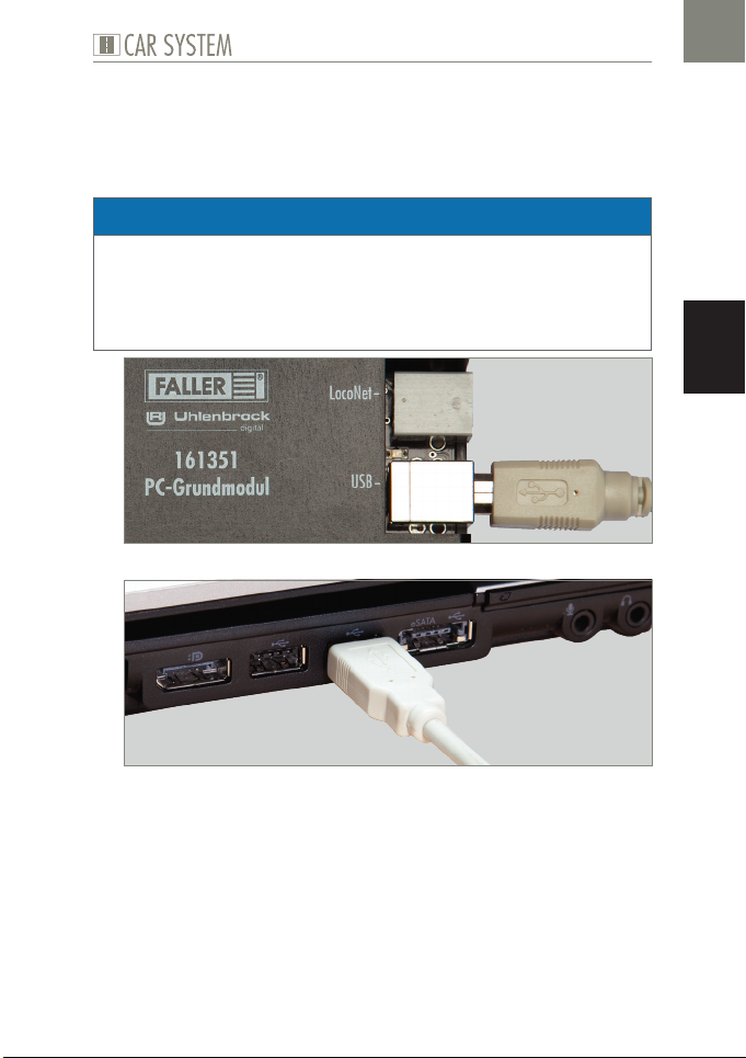
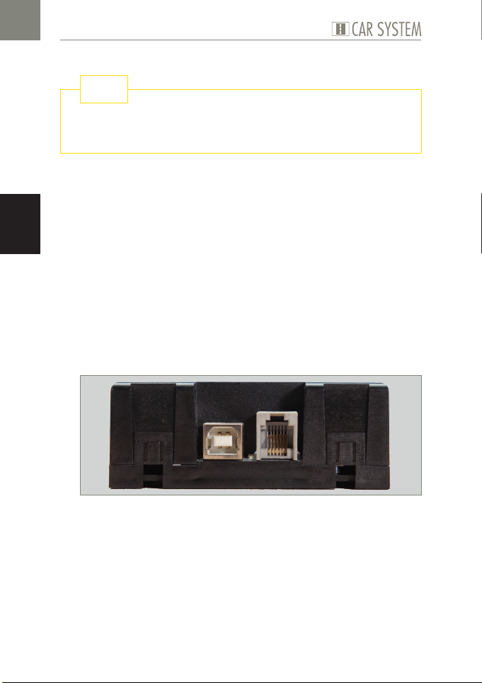
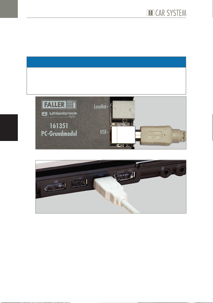
Das PC-Grundmodul verfügt über eine USB-Schnittstelle, über welche
es mit Hilfe eines handelsüblichen Druckeranschlusskabels (USB-A auf
USB-B, liegt nicht bei) mit einem PC verbunden werden kann.
ACHTUNG
Bevor das Modul mit dem PC verbunden wird, muss der Treiber auf der
beiliegenden CD installiert werden, da es sonst zu fehlerhaften Einstellungen im Betriebssystem kommen kann. Dies würde dazu führen, dass
die Software das Modul nicht ordnungsgemäß erkennt und somit auch
nicht steuern kann!
Abb. 8: Buchse am Modul
DE
Abb. 9: Buchse am PC
X
Vergewissern Sie sich, dass der korrekte Treiber installiert ist.
X
Verbinden Sie das USB Kabel mit der USB-B Buchse des PC-Grundmoduls, siehe Abb. 8
X
Verbinden Sie das USB Kabel mit der USB-A Buchse Ihres PCs, siehe
Abb. 9
Die Hardwareerkennung wird jetzt dem Gerät automatisch den korrekten
Treiber zuweisen.
13
Page 14
DE
Grund- und Erweiterungsmodul anschließen
TIPP
Weitere Informationen zur Treiberinstallation erhalten Sie in Kapitel 5
»Treiber- und Softwareinstallation«.
Weitere LocoNet-Module anschließen
Sowohl das PC-Grundmodul, als auch das Erweiterungsmodul verfügen über
LocoNet-Buchsen. Diese dienen dazu, weitere LocoNet-Module an einem
vorhandenen Modul anzuschließen.
Hinweis:
Die Reihenfolge der angeschlossenen Module ist unabhängig von ihrer
späteren Nummerierung.
X
Achten Sie darauf, dass alle Module nacheinander angeschlossen werden.
Module von FALLER und Module anderer Anbieter können miteinan-
der kombiniert werden.
Das Erweiterungsmodul kann auch direkt an eine LocoNet-fähige Digi-
talzentrale (z.B. Uhlenbrock Intellibox II) angeschlossen und darüber
betrieben werden.
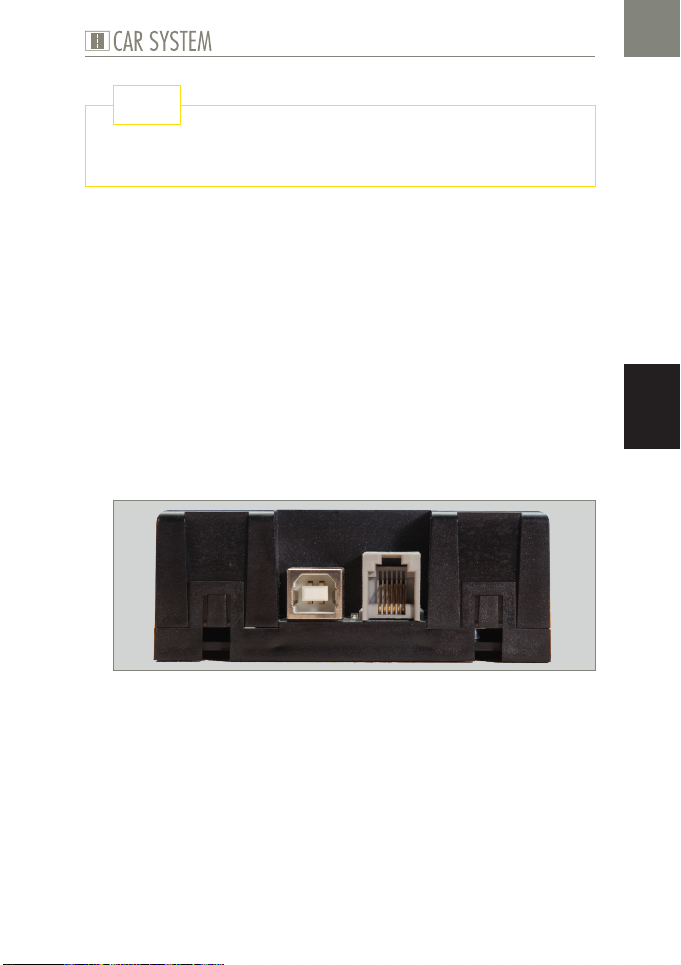
Abb. 10: LocoNet-Buchse am Grundmodul
14
Page 15
Grund- und Erweiterungsmodul anschließen
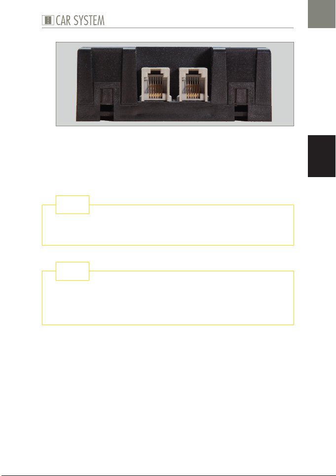
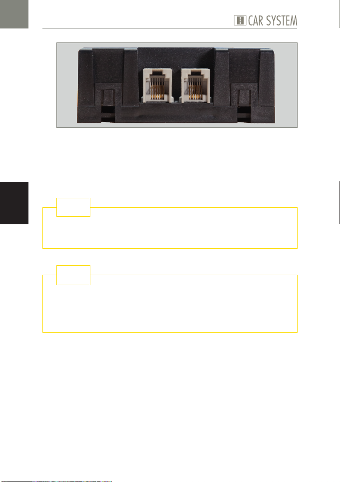
Abb. 11: LocoNet-Buchse am Erweiterungsmodul
X
Verbinden Sie das LocoNet-Kabel (liegt nicht bei) mit einem der LocoNet-Anschlüsse des ersten Moduls, siehe Abb. 10.
X
Verbinden Sie dann das LocoNet Kabel mit einem der LocoNetAnschlüsse des zweiten Moduls, siehe Abb. 11.
TIPP
LocoNet-Kabel (z.B. von Uhlenbrock) erhalten Sie im gut sortierten
Modell-Fachhandel.
TIPP
Der direkte Draht zum FALLER-Kundendienst:
Telefon + 49 (0) 77 23 / 651-106
E-Mail [email protected]
DE
15
Page 16
Treiber- und Softwareinstallation
5. Treiber- und Softwareinstallation
DE
Systemvoraussetzungen
PC mit Betriebssystem Windows 2000 oder neuer
Freie USB Schnittstelle
30 MB freier Festplattenplatz
Software installieren
ACHTUNG
Bevor das Modul mit dem PC verbunden wird, muss der Treiber von der
beiliegenden CD auf Ihrem PC installiert werden, da es sonst zu fehlerhaften Einstellungen im Betriebssystem kommen kann. Dies würde dazu
führen, dass die Software das Modul nicht ordnungsgemäß erkennt und
somit auch nicht steuern kann!
X
Legen Sie die CD-ROM in das Laufwerk. Der Installationsprozess startet automatisch.
X
Beginnen Sie mit der Installation des Treibers.
X
Wählen Sie die weiteren gewünschten Optionen im gezeigten Menü aus.
X
Folgen Sie den Anweisungen während der Installation.
Hinweis:
X
Falls das Installationsprogramm auf Ihrem PC nicht automatisch gestartet wird, öffnen Sie im Dateimanager oder Windows-Explorer das CDROM Laufwerk und starten Sie die Anwendung »CDRUN.EXE« per
Doppelklick.
16
Page 17
6. Die Software »Car System 2«
Die Software »Car System 2«
Bei der Software »Car System 2« handelt es sich um ein Programm, das Sie
bei der Einrichtung Ihrer Module unterstützt. Mit Hilfe dieser Software können Sie ganz einfach anhand der grafischen Benutzeroberfläche Modulnummern, Digitaladressen und Rückmeldenummern vergeben.
ACHTUNG
Bevor Sie die Software zum ersten Mal starten, sollte nur das PC-Grundmodul am PC angeschlossen sein, da die Software dann jedes weitere
Modul als neu erkennt und den Modulen fortlaufende Nummern zuweist.
Sollten zuvor schon mehrere Module zusammengesteckt worden sein,
kann dieser Automatismus sonst zu widersprüchlichen Ergebnissen führen.
X
Trennen Sie alle LocoNet-Verbindungen.
X
Vergewissern Sie sich, dass das Grundmodul korrekt mit Spannung versorgt wird.
X
Verbinden Sie die USB-Buchse des Moduls mit dem PC.
X
Starten Sie die Software.
HINWEIS:
X
Das PC-Grundmodul und die verwendete Schnittstelle werden im Regelfall automatisch erkannt. Sollte dies nicht funktionieren, wechseln Sie
in der angegebenen Auswahl den COM-Port. Sollte sich das Fenster
zur Änderung des Anschlusses nicht automatisch öffnen, können Sie es
unter Allgemein >> Optionen aufrufen.
DE
17
Page 18
DE
Die Software »Car System 2«
Das Anwendungsfenster
Abb. 12: Das Anwendungsfenster
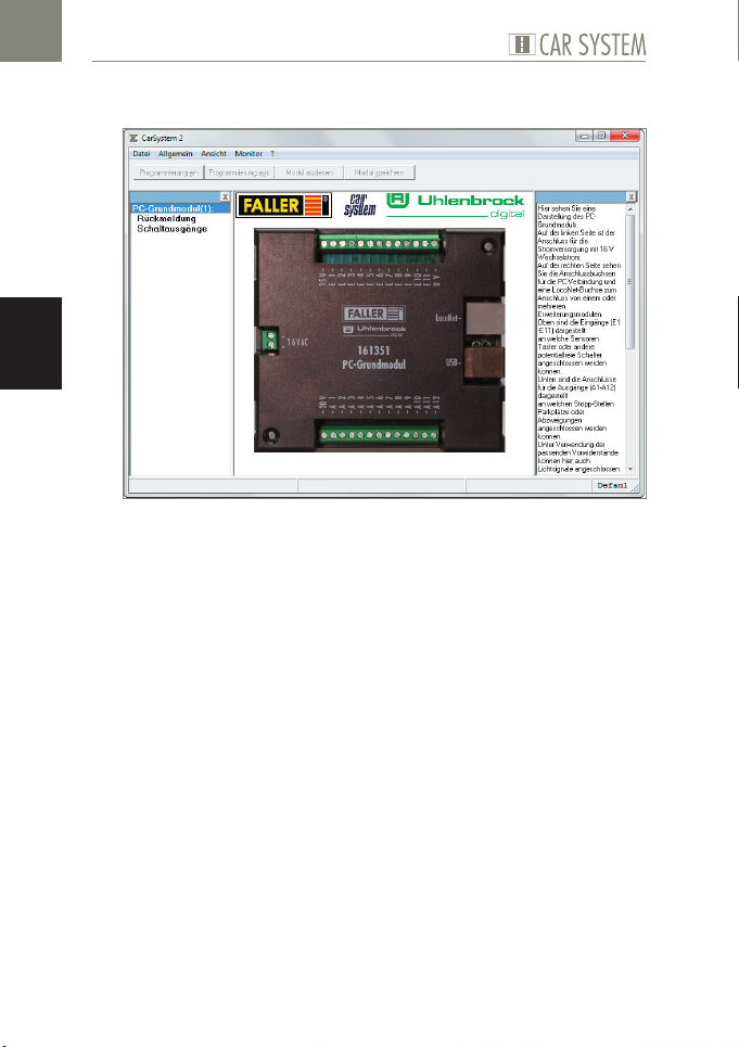
Im oberen Bereich des Anwendungsfensters befindet sich die Menüleiste
mit den Menüs Datei, Allgemein, Ansicht und Monitor.
Darunter befinden sich die Knöpfe »Programmierung ein«, »Program-
mierung aus«, »Modul auslesen« und »Modul speichern«.
Auf der linken Seite des Anwendungsfensters erscheinen die bereits
erkannten Module mit den dazugehörigen Modulnummern.
Auf der rechten Seite befindet sich ein Hilfefenster, in welchem zu jedem
Arbeitsschritt wichtige Informationen angezeigt werden.
Module hinzufügen
Wenn die Software korrekt installiert wurde und das Grundmodul kor-
rekt mit dem PC verbunden ist, wird dieses als erstes in der Modulliste
dargestellt. Alle weiteren, neuen Module werden automatisch erkannt.
X
Schließen Sie bei laufender Software ein weiteres Modul an.
X
Bestätigen Sie die Abfrage mit OK.
Sobald ein neues Modul erkannt wurde, erscheint es in der Übersicht
auf der linken Seite.
18
Page 19
Die Software »Car System 2«
Module entfernen
Es kann immer nur das letzte Modul einer Reihe entfernt werden! Soll-
ten Sie also bspw. das vierte Modul von insgesamt fünf Modulen entfernen wollen, müssen Sie zunächst das Modul 5 und dann das Modul
4 entfernen.
X
Starten Sie die Software »Car System 2«.
X
Wählen Sie die Menüpunkte Allgemein >> Modul Werkseinstellungen.
X
Entfernen Sie nun das Verbindungskabel zum betreffenden Modul.
Einstellungen
Abb. 13: Modul im Anwendungsfenster
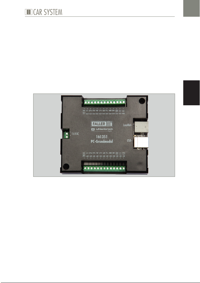
Im mittleren Bereich des Anwendungsfensters befindet sich eine Dar-
stellung des PC-Moduls.
Auf der linken Seite ist der Anschluss für die Stromversorgung mit 16 V
Wechselstrom zu sehen.
Auf der rechten Seite sind die Anschlussbuchsen für die PC-Verbindung
und eine LocoNet-Buchse zum Anschluss von einem oder mehreren
Erweiterungsmodulen zu sehen.
Oben sind die Eingänge (E1 - E11) dargestellt, an welche Sensoren, Tas-
ter oder andere potentialfreie Schalter angeschlossen werden können.
Unten sind die Anschlüsse für die Ausgänge (A1 - A12) dargestellt, an
welche Stopp-Stellen, Parkplätze oder Abzweigungen angeschlossen
werden können.
DE
19
Page 20
DE
Die Software »Car System 2«
Unter Verwendung der passenden Vorwiderstände können hier auch
Lichtsignale angeschlossen werden.
X
Klicken Sie die Eingänge E1 - E11 bzw. die Ausgänge A1 - A12, um zu
den dazugehörigen Einstellungen zu gelangen.
ACHTUNG
Abhängig vom Funktionselement muss einer der Anschlüsse mit dem Ausgang (A1 - A12) verbunden werden und der andere mit 15 V oder 20 V:
Stopp-Stelle: 20 V
Parkplatz: 20 V
Abzweigung: 15 V
Lichtsignale: 15 V mit Vorwiderstand!
X
Sensoren oder Taster verbinden Sie mit einem Anschluss an einem Eingang (E1 - E11) und mit dem anderen Anschluss mit 0 V.
Eingänge konfigurieren
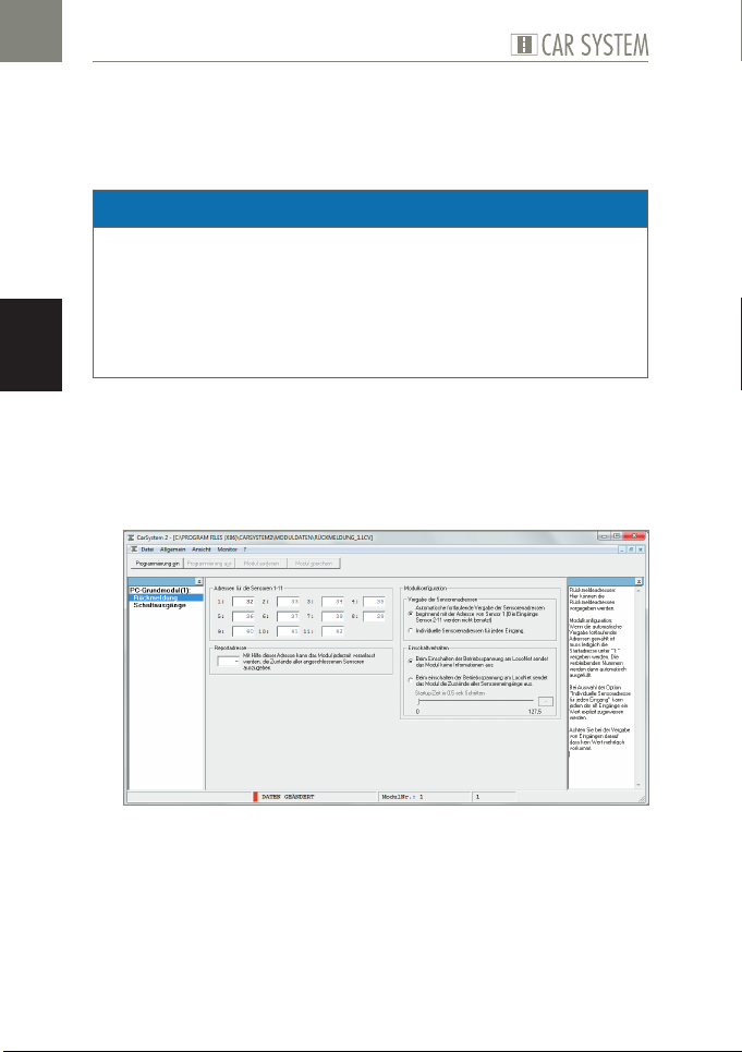
Durch Anklicken der Eingänge auf der Abbildung des ausgewählten Moduls
gelangen Sie in die dazugehörigen Einstellungen.
Abb. 14: Eingänge konfigurieren
Hier können die Rückmeldeadressen vorgegeben werden.
Modulkonfiguration:
Wenn die automatische Vergabe fortlaufender Adressen gewählt ist,
muss lediglich die Startadresse unter »1« vergeben werden. Die verblei-
benden Nummern werden dann automatisch ausgefüllt.
20
Page 21
Die Software »Car System 2«
Bei Auswahl der Option »Individuelle Sensoradresse für jeden Eingang«
kann jedem der elf Eingänge ein Wert explizit zugewiesen werden.
X
Achten Sie bei der Vergabe von Eingängen darauf, dass kein Wert mehr-
fach vorkommt.
Ausgänge konfigurieren
Durch Anklicken der Ausgänge auf der Abbildung des ausgewählten Moduls
gelangen Sie in die dazugehörigen Einstellungen.
Abb. 15: Ausgänge konfigurieren
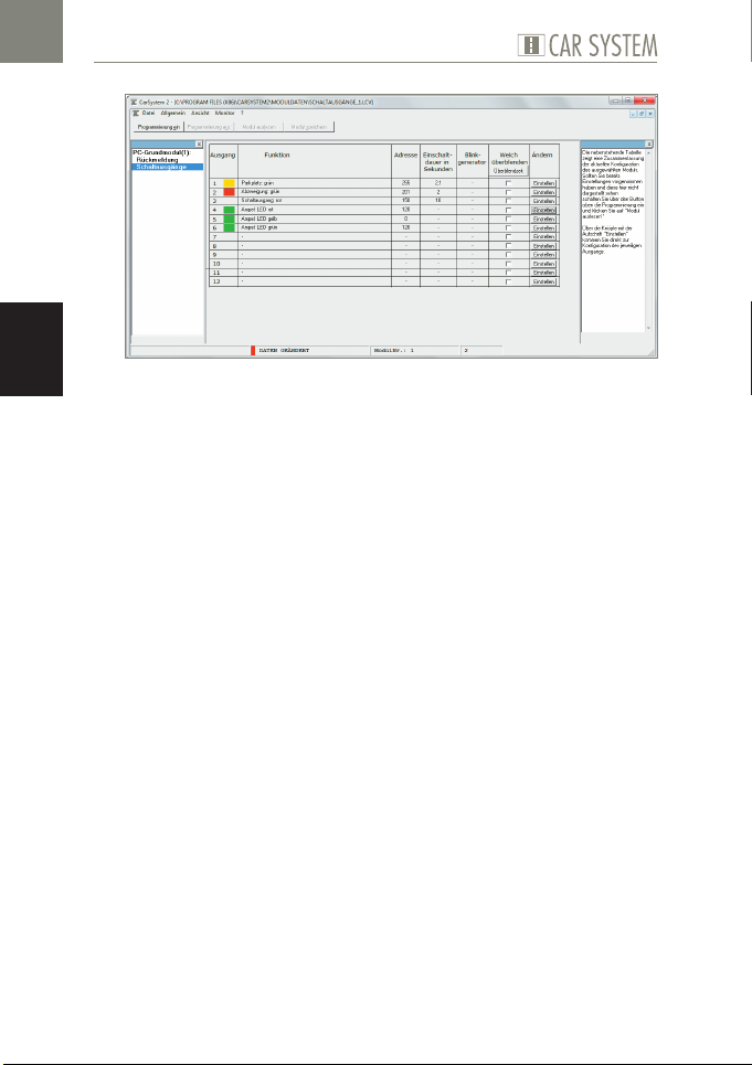
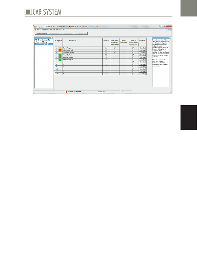
Die dargestellte Tabelle zeigt eine Zusammenfassung der aktuellen Konfigu-
ration des ausgewählten Moduls.
X
Sollten Sie bereits Einstellungen vorgenommen haben und diese hier nicht
dargestellt sehen, schalten Sie über den Button oben »Programmierung
ein« die Programmierung ein und klicken Sie auf »Modul auslesen«.
Über die Knöpfe mit der Aufschrift »Einstellen« kommen Sie direkt zur Kon-
figuration des jeweiligen Ausgangs.
DE
21
Page 22
Die Software »Car System 2«
DE
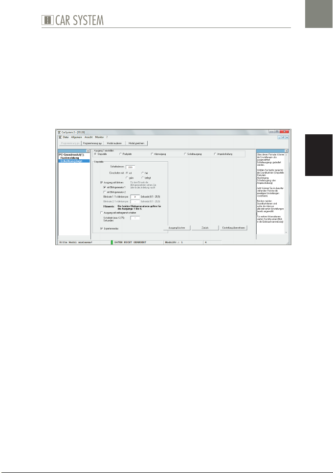
Abb. 16: Einstellungen des Schaltausgangs
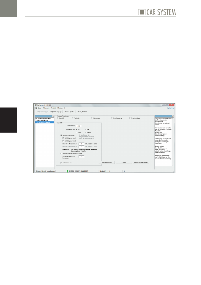
Über dieses Formular können die Einstellungen des ausgewählten Schalt-
ausgangs geändert werden.
X
Wählen Sie hierfür zunächst die Grundfunktion (Stopp-Stelle, Parkplatz,
Abzweigung, Schaltausgang oder Ampelschaltung).
X
Nehmen Sie im darunter stehenden Fenster die jeweiligen Einstellun-
gen vor.
Im Normalfall sind die meisten Funktionen ausgegraut und mit Stan-
dardwerten belegt. Sollten Sie diese Einstellungen verändern wollen,
müssen Sie den »Expertenmodus« aktivieren.
Stopp-Stelle, Parkplatz, Abzweigung, Schaltausgang
Schaltadresse
Die Schaltadresse ist die Adresse in Ihrem Digitalsystem, mit welcher eine
Funktion ausgelöst werden soll. Hier können sowohl Magnetartikeladressen
als auch Rückmeldeadressen eingegeben werden.
Mit den nachfolgenden Auswahlknöpfen können sie festlegen, bei welchem Zustand (Magnetartikel: rot oder grün, Rückmelder: belegt oder frei)
die Aktion ausgeführt werden soll.
Blinkgenerator
Die Ausgänge können auch blinken. Geben Sie hierzu an, welche Ausgänge
blinken sollen und mit welcher Frequenz dies geschehen soll.
22
Page 23

Die Software »Car System 2«
Zeitbegrenzung
Um einen Schaden an den angeschlossenen Funktionselementen durch Dauerbelastung zu vermeiden, können sie hier eine Zeit (max. 12,75 sec) vorwählen. Sollte dieses Feld nicht ausgefüllt werden, bleibt der Anschluss bis
zur Änderung des Zustands der Digitaladresse eingeschaltet.
Ampelschaltung
Die Module verfügen über eine besondere Logik, um auch Kreuzungen oder
Fußgängerampeln korrekt nachzubilden. Hierzu wird nur eine Digitaladresse
benötigt, welche bis zu vier Ausgänge steuert. Die ersten drei Ausgänge bilden hier das Lichtsignal für die Ampel, der vierte Ausgang wird für die dazugehörige Stopp-Stelle benötigt.
X
Wählen Sie zunächst, ob Sie eine Ampel mit oder ohne Stopp-Stelle
anschließen möchten.
Schaltadresse
Die Schaltadresse ist die Adresse in Ihrem Digitalsystem, mit welcher eine
Funktion ausgelöst werden soll. Hier können sowohl Magnetartikeladressen
als auch Rückmeldeadressen eingegeben werden.
Ausgänge
Hier werden die Anschlussnummern an Ihrem Modul angezeigt (A1 - A12).
DE
23
Page 24
DE
RoHS
EMC
tested
Technische Daten und Symbole
7. Technische Daten und Symbole
Elektrische Werte
Bezeichnung Wert
Spannungsversorgung 16 V Wechselspannung
Frequenzbereich 50/60 Hz
Leistungsaufnahme 3,2 W
Tab. 1: Elektrische Werte
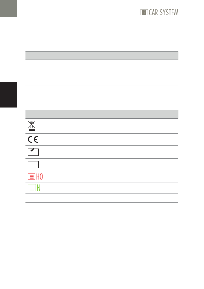
Symbole
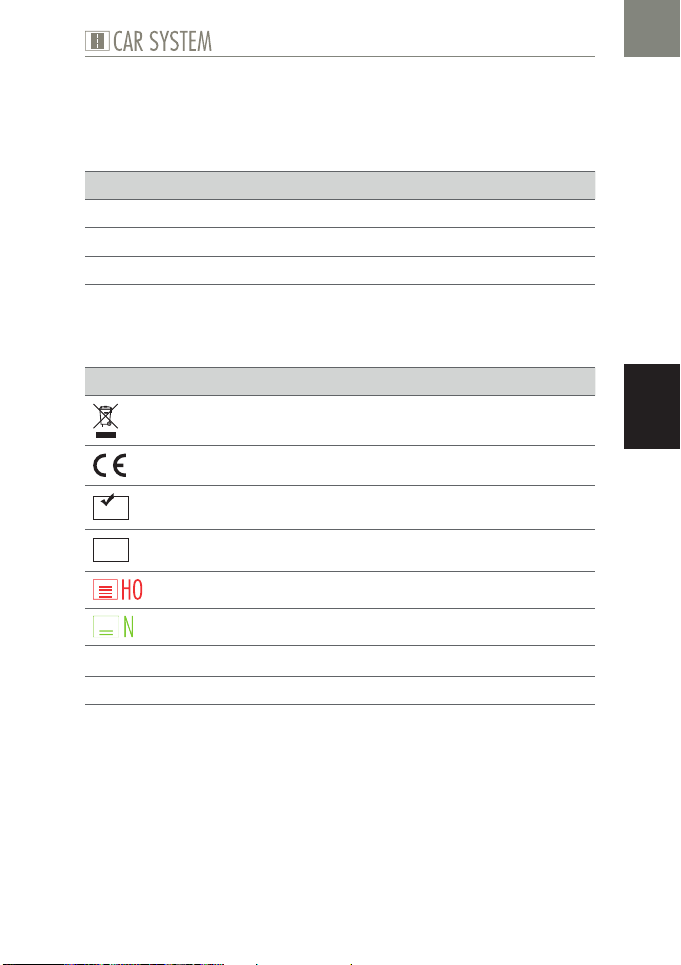
Symbol Bedeutung
Das Produkt unterliegt der europäischen WEEE-Richtlinie
CE-Konformitätskennzeichen
CE-Konformität inkl. RoHS-Richtlinie
CE-Konformität inkl. EMV-Richtlinie
1:87/H0/Spurweite 16,5 mm
u
g
Tab. 2: Symbole
24
1:160/N/Spurweite 9 mm
Handlungsaufforderung
Hinweis
Page 25
Contents
1. FALLER Car System – It’s going digital............................................ 26
2. Safety and responsibility ................................................................. 27
Proper use...................................................................................... 27
For your safety ............................................................................... 27
Environmentally friendly disposal ................................................... 28
3. General view of product ................................................................. 29
Articles supplied ............................................................................. 29
Components of the PC-standard module ...................................... 30
Components of the Expansion module .......................................... 31
4. Connecting basic and expansion modules ...................................... 32
Connecting the supply voltage ....................................................... 32
Connecting checkback contacts ..................................................... 33
Connecting functional elements ..................................................... 34
Building up a connection with a computer ..................................... 36
Connecting additional LocoNet modules ........................................ 37
5. Driver and software installation ...................................................... 39
System requirements ...................................................................... 39
Installing software .......................................................................... 39
6. »Car System 2« software ............................................................... 40
The application window ................................................................. 41
Adding modules ............................................................................. 41
Removing modules ........................................................................ 42
Settings .......................................................................................... 42
Configuring inputs ......................................................................... 43
Configuring outputs ....................................................................... 44
Stop point, parking space, branch-off junction, switching output ... 45
Traffic light operation ..................................................................... 46
7. Technical data and symbols ............................................................ 47
EN
25
Page 26
EN
FALLER Car System – It’s going digital
1. FALLER Car System – It’s going digital
Congratulations – You have found the right thing!
With the control modules from FALLER digital series you are able right now
to control all the functional elements present on your model installation via
a digital control unit DCC or a personal computer.
The PC-standard module features 11 inputs and 12 outputs as well as a USB
interface allowing to connect the module to a computer. It is also equipped
with a LocoNet interface allowing to expand the system with as many other
LocoNet modules as you want.
Each expansion module will add 11 inputs and 12 outputs to your system.
The »Car System 2« software allows to configure the modules easily via a
personal computer.
Last but not least, the »Win-Digipet« demonstration version enclosed with
every basic module suitable for personal computers will give you access to
the automatic control of model installations via a personal computer.
Gebr. FALLER GmbH wishes you a lot of creative ideas and plenty of fun
with your new acquisition!
26
Page 27
Safety and responsibility
2. Safety and responsibility
Proper use
This product is a scale modeling article aimed at ambitious modellers and
collectors, and no toy. It is designed for use on a model installation. It may
exclusively be operated together with the accessories and add-on devices
recommended by FALLER. Basically, FALLER products are developed and
designed for the hobby sector, not for permanent operation. This product
is intended for use at average ambient temperature and relative humidity.
Please operate the product only indoors, and avoid any atmospheric influences. Any other use will be considered not to be in conformity with the proper
use or intended purpose. Gebr. FALLER GmbH will assume no responsibility for any damage or defect resulting from improper use or the non-observance of the directions given in the instruction manual or the accompanying
safety recommendations.
Operating and storage conditions
X
Observe the following operating conditions: 15–40 °C, up to 75 % rela-
tive humidity, do not allow the formation of dew.
X
Observe the following storage conditions: 10–60° C, up to 85 % rela-
tive humidity, do not allow the formation of dew.
EN
For your safety
X
Carefully read through the instruction manual and the accompanying
safety recommendations before use.
X
Pay attention to the safety recommendations and warnings given in
the instruction manual, in the accompanying safety recommendations
or provided on the product.
27
Page 28
EN
Safety and responsibility
X
Always retain the instruction manual and the accompanying safety
recommendations available near to the product itself.
X
Hand over the product to third persons only together with the instruc-
tion manual and the accompanying safety recommendations.
Environmentally friendly disposal (WEEE)
Products that are labeled with the symbol of a crossed dustbin must not, at
the end of their life span, be disposed of with common household waste,
but must be handed over to a collecting point that recycles electrical and
electronic equipment. The symbol on the product, in the instruction manual
or on the packaging calls the user's attention to such obligation. All materials used are recyclable according to their marking. When allowing recycling,
the reutilization of materials, or any other form of recycling used equipment,
you will make a valuable contribution to the protection of our environment.
Please enquire from your local authorities which disposal companies are relevant in your vicinity.
X
Please observe the local regulations regarding waste disposal.
X
Please observe the WEEE Directive in the version currently applicable.
X
Before removing batteries, rechargeable or not, disconnect the product
from the power supply.
X
Remove any batteries, rechargeable or not, that may be present in a
product before scrapping it.
Advice pursuant to the BattG (German Regulations regarding Batteries)
Batteries, rechargeable or not, must not be disposed of with household
waste, and consumers are under a legal obligation to return them after use
to a municipal collecting point or to the local trade. Used batteries contain
pollutants that may be harmful to you or the environment if they are not
stored or disposed of properly. Batteries also contain precious raw materials
such as, for instance, iron, zinc, manganese or nickel that can be recycled.
After use, consumers may return batteries free of charge either to us or in
their nearest vicinity (e.g. in local shops or at municipal collecting points).
On doing so, any return by end users at selling points is limited to the usual
quantities and to such used batteries that the distributor carries or has carried
in stock as new batteries. The symbol of a crossed dustbin means that batteries, rechargeable or not, must not be disposed of with household waste.
X
Please dispose of all types of batteries at the public collecting points that
are responsible for such service and are appointed by your authorities.
28
Page 29
3. General view of product
Articles supplied
PC-standard module (only in article no. 161351)
Expansion module (only in article no. 161352)
CD-ROM (only in article no. 161351)
Instruction manual
General view of product
EN
29
Page 30
EN
General view of product
Components of the PC-standard module
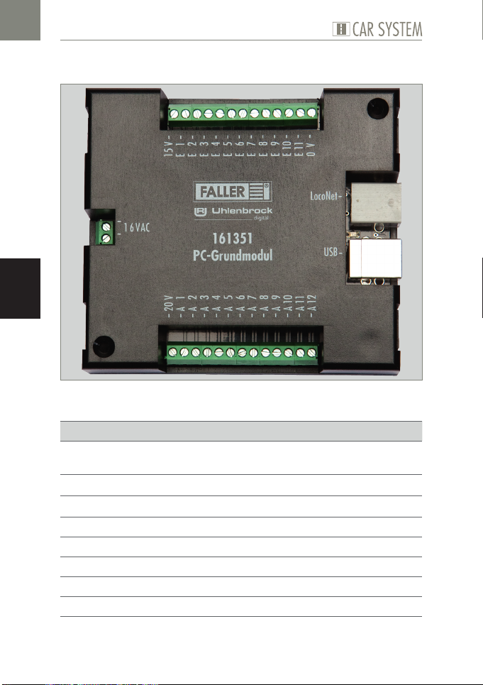
Fig. 1: PC-standard module
Ports Description
»16 VAC« Port for supply voltage
(16 V alternating voltage)
»USB« USB computer port
»LocoNet« LocoNet interface
»E 1 - E 11« 11 inputs
»0 V« 0 V for inputs
»A 1 - A 12« 12 outputs
»15 V« 15 V for outputs
»20 V« 20 V for outputs
30
Page 31
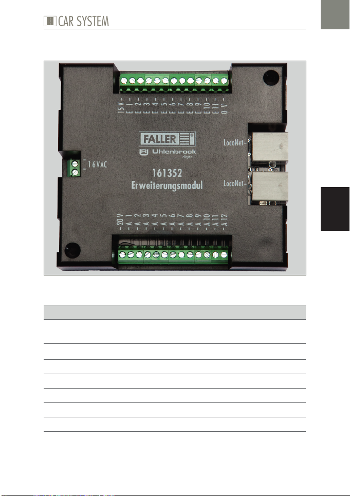
Components of the Expansion module
Fig. 2: Expansion module
Ports Description
»16 VAC« Port for supply voltage
(16 V alternating voltage)
»LocoNet« LocoNet interface
»E 1 - E 11« 11 inputs
»0 V« 0 V for inputs
»A 1 - A 12« 12 outputs
»15 V« 15 V for outputs
»20 V« 20 V for outputs
General view of product
EN
31
Page 32
Connecting basic and expansion modules
4. Connecting basic and expansion modules
Connecting the supply voltage
The modules are powered by 16 V alternating current.
EN
TIP
The required alternating current can be generated using FALLER’s 50
VA, 50 to 60 Hz transformer bearing the article number 180641, for
instance.
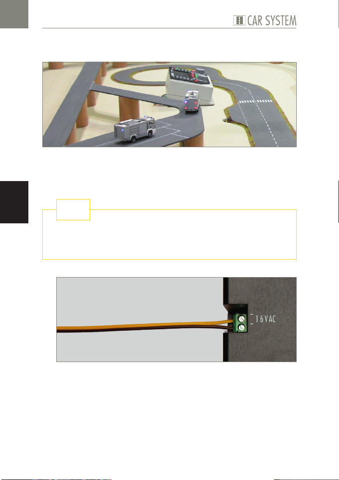
Fig. 3: Connecting side
X
Connect the modules to 16 V alternating current, see Fig. 3.
32
Page 33
Connecting basic and expansion modules
Connecting checkback contacts
The inputs of the modules must all be potential-free.
TIP
You may connect here any push buttons, sensors, switching tracks
or the potential-free outputs of switching decoders. For checkback
signals coming from the road use FALLER sensors, article number
161773.
NOTICE
Never connect to the inputs of the modules any live components such
as, for instance, the outputs of points decoders. This might destroy the
modules.
EN
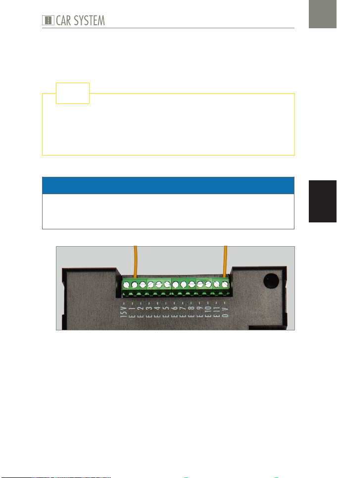
Fig. 4: Checkback contacts
X
Connect one end of the sensor to the ground (0 V) and the other end
to the required input (E1 - E11), see Fig. 4.
33
Page 34
EN
Connecting basic and expansion modules
TIP
Do you want to find out more about the subject? Quench your thirst
for knowledge on our homepage – www.faller.de. You will find there
interesting background information and a lot of creative suggestions
for all areas of model making.
Connecting functional elements
The outputs of the modules allow to control various consuming devices. Such
devices may be on the one hand the functional elements of FALLER Car System (branch-off junction, parking space and stop point) or other consuming
devices such as LEDs or lamps.
ADVICES:
When connecting LEDs, always make sure that you use the right pro-
tective resistors. Such resistors can be determined using the »Car System 2« software via menu point Allgemein >> Vorwiderstandsrechner
[General >> Protective resistor calculator].
Connect parking spaces and stop points to 20 V. On the contrary, con-
nect branch-off junctions and lighting fittings to 15 V.
When connecting a stop point, make sure you observe the polarity. If a
vehicle should stop in such a place, the north pole of its coil must show
upwards. To test that it is so, hold the steering slider of a vehicle above
the middle of the stop point when it is switched on. If the steering slider is repelled, the north pole shows upwards and the polarity is correct. On the contrary, if a vehicle of FALLER digital series should switch
over to its second driving speed in that place, it’s the south pole that
has to show upwards.
TIP
For further information regarding the connection of consuming
devices, please refer to the instruction manual of the relevant device.
34
Page 35
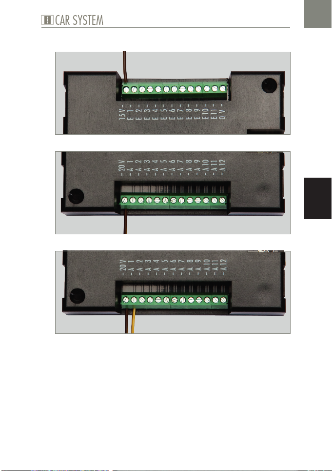
Fig. 5: Screw terminal 15 V
Fig. 6: Screw terminal 20 V
Connecting basic and expansion modules
EN
Fig. 7: Screw terminal output (A1 - A12). For instance 20 V.
X
Connect one of the connection cables of the consuming device to the
voltage intended for that purpose (15 V or 20 V), see Fig. 5 and Fig. 6.
X
Connect the other end of the consuming device to the required output, see Fig. 7.
35
Page 36
EN
Connecting basic and expansion modules
Building up a connection with a computer
The PC-standard module features a USB interface allowing it to be connected with a personal computer by means of a commercially available printer
connection cable (USB-A to USB-B, not supplied).
NOTICE
Prior to connecting the module to the computer, a driver has to be installed from the enclosed CD, otherwise the operating system might feature faulty settings. This would result in the software not identifying the
module correctly and thus not being able to control it either!
Fig. 8: Socket on the module
Fig. 9: Socket on the personal computer
X
Make sure you have installed the right driver.
X
Connect the USB cable to the USB-B socket of the PC-standard module,
see Fig. 8.
X
Connect the USB cable to the USB-A socket of your computer, see Fig. 9.
The hardware identification will now automatically assign the right driver
to the device.
36
Page 37
Connecting basic and expansion modules
TIP
You will find further information on the installation of drivers in
Chapter 5 »Driver and software installation«.
Connecting additional LocoNet modules
Both the PC-standard module and the expansion module feature LocoNet
sockets. These sockets are provided to connect additional LocoNet modules to any module already existing.
ADVICES:
The order in which the modules are connected is independent of their
subsequent numbering.
X
Make sure you connect all modules one after the other.
Modules by FALLER and modules from other suppliers may be com-
bined with each another.
The expansion module may also be directly connected to any LocoNet
capable digital control unit DCC (e.g. Uhlenbrock Intellibox II) and be
operated via such control unit.
EN
Fig. 10: LocoNet socket on basic module
37
Page 38
Connecting basic and expansion modules
Fig. 11: LocoNet socket on expansion module
X
Connect the LocoNet cable (not supplied) to one of the LocoNet ports
of the first module, see Fig. 10.
X
Next, connect the LocoNet cable to one of the LocoNet ports of the
second module, see Fig. 11.
EN
TIP
You will find LocoNet cables (e.g. by Uhlenbrock) in well assorted
specialized model-making shops.
TIP
Direct line to FALLER’s customer service department:
Phone + 49 (0) 77 23 / 651-106
E-mail [email protected]
38
Page 39
Driver and software installation
5. Driver and software installation
System requirements
PC with operating system Windows 2000 or more recent
Free USB interface
30 MB free hard-disk storage capacity
Installing software
NOTICE
Prior to connecting the module to the computer, the driver has to be installed from the enclosed CD, otherwise the operating system might feature faulty settings. This would result in the software not identifying the
module correctly and thus not being able to control it either!
EN
X
Insert the CD-ROM into the drive. The installation procedure will start
automatically.
X
Begin with the installation of the driver.
X
Select the relevant options you require in the menu displayed.
X
Follow the instructions given during the installation.
ADVICE:
X
If the installation program does not automatically start on your computer,
open the CD-ROM drive in the file manager or in Windows Explorer and
start the application »CDRUN.EXE« by clicking twice on the file name.
39
Page 40
»Car System 2« software
6. »Car System 2« software
»Car System 2« software is a program that helps you install your modules.
That software allows you to assign easily module numbers, digital addresses
and checkback numbers by means of its graphical user interface.
EN
NOTICE
When starting the software for the first time, only the PC-standard module
should be connected to the computer as that software identifies any additional module as being new and assigns serial numbers to the modules.
Should previously several modules be connected already, that automatism might result in contradictory data being stored.
X
Disconnect any existing LocoNet connections.
X
Make sure the basic module is supplied with the right voltage.
X
Connect the USB socket of the module to the computer.
X
Start the software.
ADVICE:
X
As a rule the PC-standard module and the interfaces used are automatically identified. Should such procedure not function properly, change
the COM port in the selection proposed. Should the window to be used
to change the port not automatically open, you can open it under menu
point Allgemein >> Optionen [General >> Options].
40
Page 41
»Car System 2« software
The application window
Fig. 12: The application window
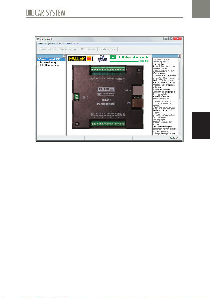
At the top of the application window you will find the menu bar fea-
turing the menus File, General, View and Monitor.
Below you will find the buttons »Programmierung ein«, »Program-
mierung aus«, »Modul auslesen« und »Modul speichern«. [»Programming on«, »Programming off«, »Select module« and »Save module«].
On the left-hand side of the application window you can see the modu-
les already detected along with the corresponding numbers.
On the right-hand side there is an help window in which important
information on each procedure is displayed.
EN
Adding modules
If the software has been properly installed and the basic module is pro-
perly connected to the computer, that basic module will be displayed in
the first place at the top of the list of modules. All other new modules
will automatically be detected.
X
With the software in operation, connect an additional module.
X
Acknowledge the enquiry with OK.
41
Page 42

EN
»Car System 2« software
As soon as a new module has been detected, it will appear in the syn-
opsis on the left.
Removing modules
Only the last module in the list can be removed! Thus, should you want
to remove for instance the fourth module of a total of five, you will have
to remove first module 5 and then, module 4.
X
Start the »Car System 2« software.
X
Select menu point Allgemein >> Modul Werkseinstellungen [General
>> Module Default settings].
X
Now disconnect the connection cable of the module concerned.
Settings
Fig. 13: Module in the application window
In the central section of the application window there is a picture of the
computer module.
On the left you can see the port used for power supply with 16 V alter-
nating current.
On the right you can see the sockets used for the connection to the
computer as well as a LocoNet socket to connect one or several expansion modules.
At the top there are the inputs (E1 - E11) to which sensors, push but-
tons or other potential-free switches can be connected.
42
Page 43
»Car System 2« software
At the bottom there are the ports for the outputs (A1 - A12) to which
stop points, parking spaces or branch-off junctions can be connected.
By using the suitable protective resistors, light signals can also be con-
nected to these outputs.
X
Click on the inputs E1 - E11 or the outputs A1 - A12 in order to go to
the relevant settings.
NOTICE
Depending on the functional element you want to use, one of its wire
will have to be connected to the output (A1 - A12) and its other wire to
15 V or 20 V:
Stop point: 20 V
Parking space: 20 V
Branch-off junction: 15 V
Light signal: 15 V with protective resistor!
X
Sensors or push buttons have to be connected with one wire leading to
one input (E1 - E11) and the other wire to 0 V.
Configuring inputs
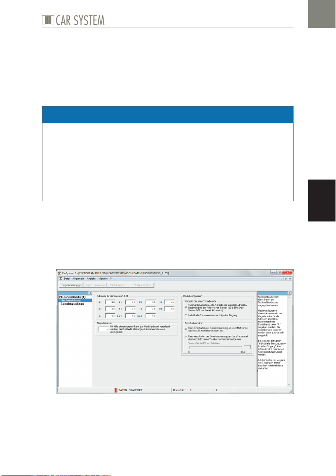
By clicking on the inputs shown in the picture of the selected module, you
go to the relevant settings to be performed.
EN
Fig. 14: Configuring inputs
Here the required checkback addresses can be specified.
43
Page 44
EN
»Car System 2« software
Module configuration:
Once you have selected the automatic allocation of consecutive addres-
ses, you merely have to allocate the first address under »1«. The remaining numbers will then be filled in automatically.
Selecting the option »Individuelle Sensoradresse für jeden Eingang«
[»Individual sensor address for each input«] makes it possible to assign
an explicit value to each one of the eleven inputs.
X
When assigning inputs, make sure that no value is used several times.
Configuring outputs
By clicking on the outputs shown in the picture of the selected module, you
go to the relevant settings to be performed.
Fig. 15: Configuring outputs
The table displayed shows a summary of the current configuration of the
selected module.
X
Should you have made some settings that are not shown in that table,
simply switch on the programming procedure using the button »Programmierung ein« [»Programming on«] at the top and click on the
option »Modul auslesen« [»Selecting module«].
By means of the buttons marked »Einstellen« [»Setting«] you directly go to
the configuration of the relevant output.
44
Page 45
»Car System 2« software
Fig. 16: Settings of the switching output
That form will allow you to change the settings of the selected switching
output.
X
To this end, first select the basic function (stop point, parking space,
branch-off junction, switching output or traffic light operation).
X
Next, make the relevant settings in the window you find below.
Normally most functions appear in grey and are assigned standard values.
If you want to change those settings, you have to activate the »Expertenmodus« [»Expert mode«].
Stop point, parking space, branch-off junction, switching output
Switching address
The switching address is the address in your digital system with which a
function has to be triggered. Here you may enter both coil item addresses
and checkback addresses.
The option buttons that follow allow you to specify in which condition (coil
item: red or green, checkback contact: occupied or unoccupied) the action
has to be performed.
EN
Flashing generator
Outputs are also able to generate a flashing. To this end, simply indicate
which outputs should flash and at which frequency this will have to occur.
45
Page 46
EN
»Car System 2« software
Time limit
To prevent a permanent load from damaging the functional elements that are
connected, you can here preselect a short period of time (maximum 12.75
sec). If that field is not filled in, the connection will remain switched on until
a change occurs in the condition of the digital address.
Traffic light operation
The modules feature a specific logical circuit allowing them to reproduce properly intersections and pedestrian stop-go lights. Such procedure requires
only one digital address that will control up to four outputs. The first three
outputs will form the light signal for the traffic light, whereas the fourth output is required for the corresponding stop point.
X
First, select whether you want to connect a traffic light with or without stop point.
Switching address
The switching address is the address in your digital system with which a
function has to be triggered. Here you may enter both coil item addresses
and checkback addresses.
Outputs
That list displays the connection numbers present on your module (A1 to
A12).
46
Page 47
Technical data and symbols
RoHS
EMC
tested
7. Technical data and symbols
Power supply
Designation Value
Supply voltage 16 V alternating current
Frequency range 50/60 Hz
Power consumption 3.2 W
Tab. 1: Power supply
Symbols
Symbol Meaning
Product is subject to the European
WEEE Directive
CE conformity label
CE Conformity incl. RoHS directive
CE Conformity incl. EMC directive
1:87/H0/16.5 mm track gauge
EN
X
g
Tab. 2: Symbols
1:160/N/9 mm track gauge
Action
Note
47
Page 48

Gebr. FALLER GmbH
Kreuzstraße 9
78148 Gütenbach
Telefon +49 (0) 77 23 / 651-0
Telefax +49 (0) 77 23 / 651-123
www.faller.de
[email protected]
© Gebr. FALLER GmbH | Sachnr. 161 351 1 / 161 352 1 | Änderungen vorbehalten | 09.04.2019
 Loading...