

Page 1
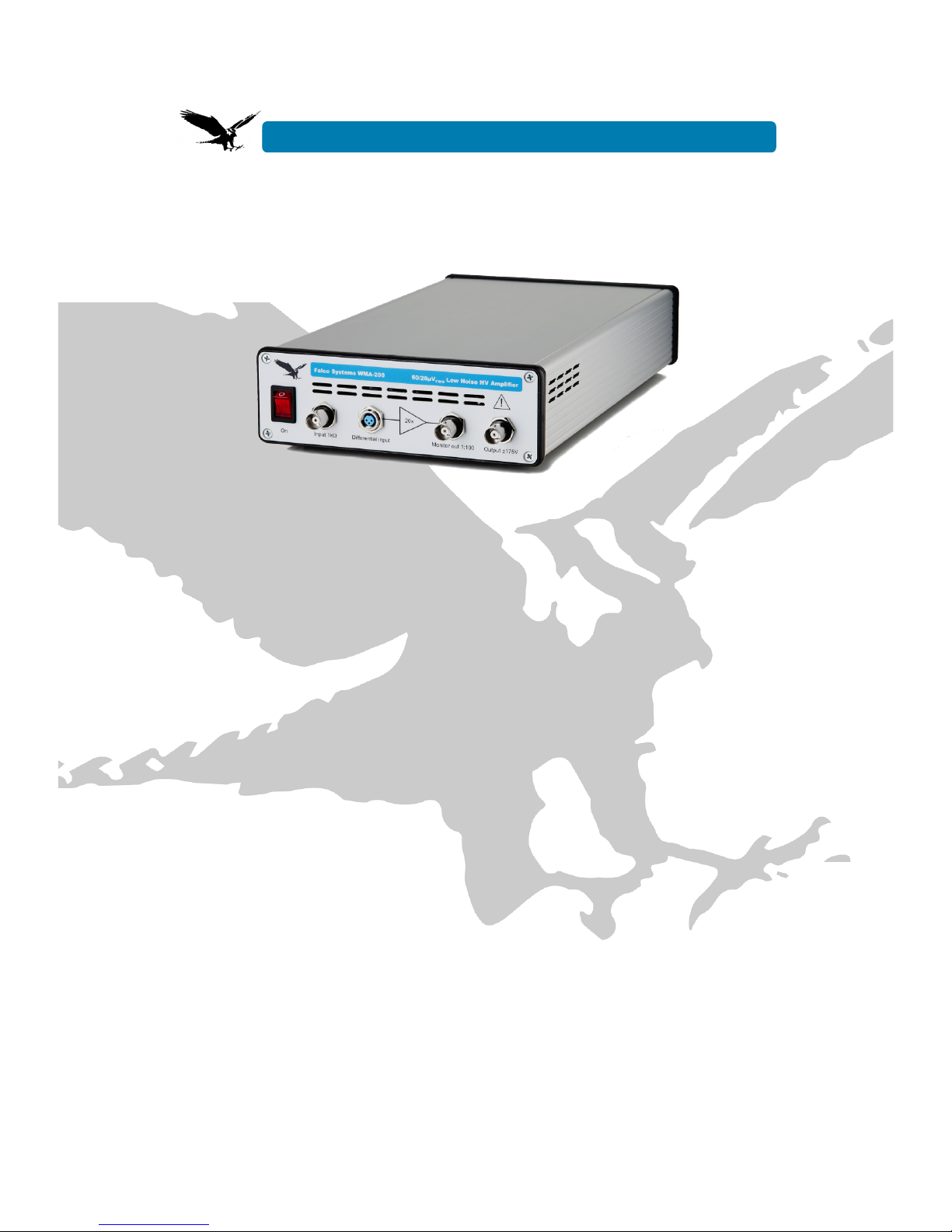
USER MANUAL
● Ultra-low output noise: ~50µV
rms
with DC – 100kHz large signal
bandwidth; ~20µV
rms
with DC – 500Hz using the supplied load capacitor
box
● High voltage: 20.0x precision amplification up to +175V and -175V
output voltage with respect to ground
● Short-circuit protected output with 275mA output current capability
● No overshoot with capacitive loads: bandwidth changes automatically
to ensure stability
● 2 inputs: a standard BNC connector, and a differential connector to
reject interference (mating connector supplied)
● BNC monitor out connector provides 1:100 replica of the output signal
About this manual
This user manual is an integral part of the
Falco Systems WMA-200 high voltage
amplifier product. Please read it carefully
and pay attention to the recommendations
and instructions for safe use.
The WMA-200 high voltage
amplifier: getting started
The Falco Systems WMA-200 model is a
high quality, high voltage, linear laboratory
amplifier optimized for experiments
requiring world-class, ultra-low output
noise. The excellent noise performance,
combined with the wide bandwidth and
large voltage range make this amplifier the
preferred choice for the most demanding
precision positioning systems. The
amplifier will routinely enable sub-atomic
positioning resolution with piezo
positioning systems and MEMS devices,
and is the ultimate ultra low noise driver
for EO-modulators, (particle) beam
steering, ultrasonics, dielectric studies,
and many other loads requiring a high
voltage drive.
The output noise level of the high voltage
amplifier is only ~50µV
rms
with its standard
large signal bandwidth of DC – 100kHz.
For even lower noise in experiments
where this large bandwidth is not required,
a capacitor load box is supplied with the
amplifier. It cuts the bandwidth to DC –
500Hz, at the same time reducing the
output noise level to an unprecedented
~20µV
rms
. Keep input and output cables as
short as possible to prevent picking up
interference from the surroundings. For
Falco Systems WMA-200 50/20µV Low noise HV Amplifier
Page 2

more information on how to connect the
amplifier for the lowest possible noise
level, please read the ‘Noise’ section later
in this manual.
The WMA-200 high voltage amplifier is
designed to be fully stable and free of
spurious signals with any capacitive load.
The amplification is a precise 20.0x (fixed,
defined by 0.1% precision resistors). The
amplifier has an output range of –175V to
+175V, a large signal bandwidth of
100kHz @ -3dB, and a slew rate of
80V/µs. The short-circuit protection with a
fast current limit of ±275mA make this
amplifier suitable for both normal daily
laboratory use and for implementing
automated measurement systems.
Recommendations:
- Never apply more than +15V (or less
than -15V) to the amplifier input to prevent
damage.
- Do not connect separate signal sources
to both the BNC and differential inputs
simultaneously, as the signal sources are
be connected together inside the amplifier.
- A short voltage spike may appear at the
output, when the amplifier is turned on or
off. Pay attention not to damage sensitive
circuitry or equipment already connected.
- The amplifier cannot be damaged by a
short-circuit condition or capacitive
loading, but two situations should be
avoided:
● Connecting a charged capacitor to
the input or output.
● Connecting a highly inductive load to
the output (such as a coil).
- Do not connect anything to the output
that can act as an antenna.
- This product should only be cleaned with
a soft, slightly moist cloth. Unplug the
WMA-200 amplifier from the mains power
before cleaning.
Safety
- This product is able to produce over
175V at more than 275mA at its output,
which is a very high level (risk of electric
shock). Safety measures should be taken
accordingly. This is indicated by the sign
above the output connector of the
amplifier.
- This product is a Class I appliance which
requires a mains connection with
protective earth.
- Always position the WMA-200 amplifier
such that the on/off power switch is easily
accessible.
- The airflow to and from the WMA-200
amplifier should not be blocked or
impeded, at the front, sides and the back.
- The internal circuitry of the amplifier
operates at high voltage. Only qualified
personnel from Falco Systems should
service this amplifier.
- Only replace fuses with the correct type:
● 230V version of the WMA-200: 250V
800mA 5x20mm slow blow.
● 115V version of the WMA-200: 250V
1.6A 5x20mm slow blow.
- The Falco Systems WMA-200 amplifier is
only suitable for indoor use in a class II
environment (domestic, light industrial).
- Non-sinusoidal mains power generators
cannot be used to power this product.
Detailed properties of the WMA200 high voltage amplifier
Inputs
Two inputs are available on the WMA-200
front panel: a standard BNC input for easy
interfacing to existing setups, and a
differential connector (TE Connectivity
T01-0560-S03) to reject interference. Such
interference is almost always present on
the incoming cable, picked up from the
environment external to the amplifier. A
mating cable connector for the differential
input (TE Connectivity T01-0550-S03) is
supplied with the amplifier.
The input impedance of both inputs of the
WMA-200 high voltage amplifier is defined
by a 1kΩ resistor to ground, in parallel with
100pF to prevent electrostatic discharge
(ESD) input damage. These resistors add
some noise to the output voltage unless a
low-impedance source (e.g. the output of a
preamplifier) is connected to the input. The
noise will be slightly higher when the
amplifier input is left open.
The 1kΩ resistors will form a voltage
divider with the output resistance of the
signal source which is used to drive the
WMA-200. If this impedance is very low,
no change in gain will be observable, but if
this source has e.g. a (commonly
encountered) 50Ω output resistance, the
apparent gain will change from 20x to a
lower but very well-defined 19.05x due to
this voltage divider effect.
Page 3
The 1kΩ resistors also add to the output
offset voltage because the offset current of
the input amplifier generates a voltage
over these resistors. This output offset
voltage is ~3mV if the BNC input is used
with a 50Ω signal generator. When both
inputs are shorted together or connected
to a low-impedance source, the offset is
reduced to ~700 µV.
Using the BNC connector, the amplifier will
amplify 20.0x, up to the maximum output
voltage. To obtain the lowest possible
noise performance possible, it is highly
recommended to use the differential input
instead of the BNC. For this purpose, a
mating connector is supplied with the
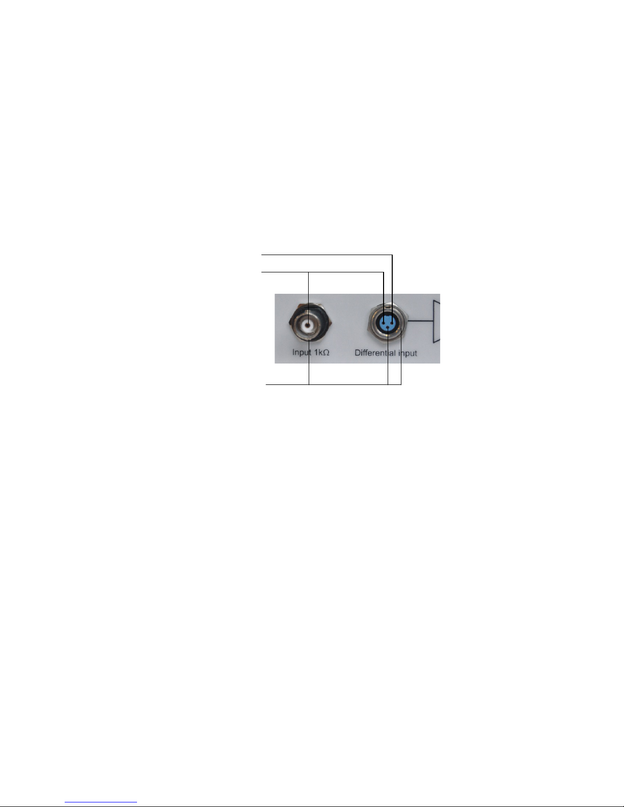
amplifier. The BNC input is internally
connected to the positive input of the
differential connector (see Fig 1 for the
connections). The negative input of the
differential connector should be supplied
with the same input signal as the positive
input, but this signal should have the
opposite polarity. Both of the differential
inputs amplify 20.0x, which means that the
absolute amplitude of either input should
be only half of the value that would be
used to drive the BNC input.
!
Figure 1. Signals to be supplied to the BNC and differential connector
A low noise amplifier like the WMA-200
model can never be made fully insensitive
to input overload conditions, as this would
limit the performance of the amplifier
significantly. For normal operation, input
voltages should remain in the –8.75V to
+8.75V range when using the BNC input,
and half this value when using the
differential connector. This will result, with
an amplification of 20.0x, in an output
voltage swing of –175V to +175V. Below 15V and above +15V, the input protection
circuitry will limit the voltage fed to the
amplifier, but the amplifier (or the signal
source) may be permanently damaged if
the current of the source is not limited.
Outputs
The WMA-200 model has a 50Ω output
resistance, and has been designed to be
fully stable with all capacitive loads. It has
been optimized for a perfect stepresponse, but it is also a very good linear
and sine-wave amplifier.
The WMA-200 amplifier has a clever
feedback system, which ensures that no
significant overshoot occurs at any
capacitive load. The bandwidth of the
amplifier is automatically reduced to
ensure stability. Instability under capacitive
loading conditions is a common problem of
other high-speed negative feedback
amplifiers, often resulting in unwanted
output overshoot voltages, and, in extreme
cases, oscillations.
Short-circuiting this amplifier will not break
down the amplifier, due to the extremely
fast current limiting circuit that has been
employed.
A monitor out signal is available on a
separate BNC connector, which provides a
1:100 replica of the output signal as seen
by the load.
Inverting (-)
Non-inverting (+)
Ground
Page 4
Cabling
The WMA-200 high voltage amplifier has
been designed for use in the most
demanding low noise experiments. As
such, the noise generated by the amplifier
is so low, that the actual performance of
the set-up in which it is used can easily be
dominated by interference picked up from
the surroundings. For optimal performance
use the differential input, with a high
quality differential cable such as STP
(shielded twisted pair), and keep the cable
as short as possible.
As the output connector is a single-ended
BNC, all interference picked up by the
output cable will be directly appear across
the connected load. The noise
performance of the amplifier has been
assessed with the inputs shorted, and the
output of the amplifier connected with a
direct coaxial connection to a low-noise
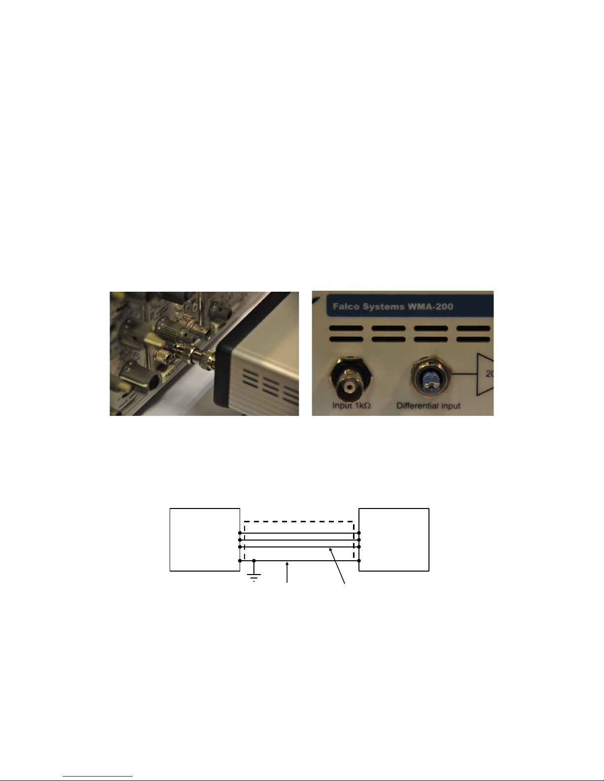
oscilloscope front end. Fig. 2 shows the
arrangement. Even a 10 centimetre output
cable increases the attainable noise level
by a few microvolts in a typical setup due
to interference pick-up. But this may not
be a problem in many applications; the
performance is still excellent by
conventional standards when a longer
coaxial cable is used. It is recommended
not to make a ground connection to the
load in any other way than via the WMA200 amplifier output connector ground, to
prevent ground loops. The optimal
arrangement of connections is given in
Fig. 3.
Figure 2. Assessment of the ultimate attainable output noise level of the WMA-200 high
voltage amplifier requires care not to beak the coaxiality of the connection. Cables should be
as short as possible (or even absent, as in this example) not to pick up any interference,
which will appear directly across the load. The differential inputs are shorted together at the
amplifier input in this example.
Figure 3. Cable arrangement recommended for the WMA-200
Noise
The noise of the amplifier is lowest when a
low-impedance source is used, because
then the 1kΩ input resistors cannot
contribute to the overall noise level. Such
a source is e.g. a pre-amplifier output or a
50Ω function generator output. To assess
the noise performance of the amplifier
without picking up interference, connect
the two input pins of the differential
Amplifier
diff. in
Generator
diff. out
Differential cable
+ +
- -
Cable shield Optional extra ground
(middle pin of connector)
Page 5
connector together wile leaving the ground
pin in the middle open (Fig. 2).
The output noise will be lowered further
when the bandwidth of the amplifier is
reduced, which happens when a
significant capacitive load is connected to
the output. This will happen automatically
when a high-capacitance piezo is
connected to the output. For all other
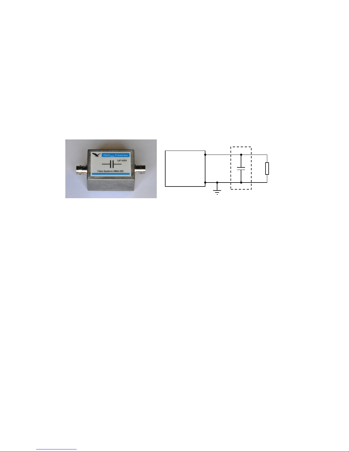
cases, a shielded 1uF load capacitor box
is supplied with the amplifier, which is
connected parallel to the load (Fig 4). This
will bring the noise down from its value of
~50µV
rms
(with a DC - 100kHz bandwith) to
only ~20µV
rms
(with a DC – 500Hz
bandwidth). If used, always connect the
capacitor box directly next to the load, so
that the box also filters away the
interference picked up by the output cable
before this interference reaches the load.
For a comprehensive treatment on the
subject of noise and interference, the
reader is referred to the Falco Systems
application note ‘High voltage amplifiers:
so you think you have noise!’, online at
www.falco-systems.com.
Figure 4. When the bandwidth- and noise reducing capacitor box is connected to the load, the
noise reduces to ~20µV
rms
, while the bandwidth is simultaneously reduced to DC – 500Hz.
The load
The output impedance of the WMA-200
model is 50Ω, to ensure stability with all
capacitive loads. The amplifier is generally
used for high-impedance applications
where the load is capacitive. This is the
case for MEMS devices, EO-modulators
and piezo’s alike. It should be noted that a
coaxial cable itself also presents a
capacitive load of approximately 100pF/m.
Matched loading with a 50Ω load circuit is
possible by connecting a 50Ω resistor in
series with the output to ground, but is not
recommended. The advantage is that
excessively long cables will not distort the
waveforms. The disadvantage is a highly
reduced voltage range (275mA in 50Ω
gives 13,75V maximum instead of 175V
maximum).
With sensitive and/or high-frequency
measurements, coaxial or shielded twisted
pair (STP) cable should be used for the
input, and a coaxial cable for the output.
The length of the cables should be
minimized. Otherwise the cables will
cause overshoot due to cable reflections
(an effect related to the finite speed of
light), and current limiting due to the cable
capacitance. Although the amplifier itself
remains fully stable, using less than 3
meter of input and output cable is
recommended for the WMA-200 amplifier
to obtain optimal results without cable
reflections, even if obtaining the lowest
possible noise performance is not
required.
Transmitter mode
This amplifier can generate a significant
amount of power at frequencies used for
radio transmission and reception. The
amplifier should not be used for
telecommunication as described in the
R&TTE directive 95/5/EC. Also for this
reason always use coaxial cables.
Amplifier characteristics
In the following pages, several amplifier
characteristics are illustrated:
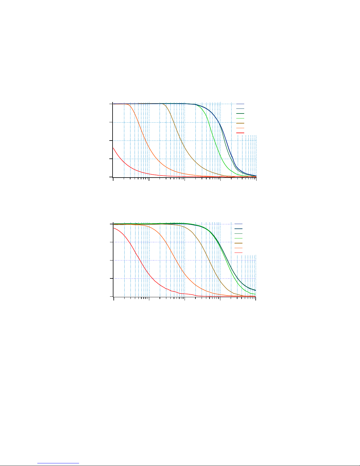
- Frequency response as a function of
capacitive load (Fig. 5, 6)
Amplifier
Capacitor box
Load
Page 6
- Rms output noise voltage versus
capacitive load (Fig. 7)
- Noise and offset without capacitor box
(Fig. 8)
- Noise and offset with capacitor box (Fig.
9)
- Noise spectrum with and without
capacitor box (Fig. 10)
- Sine and triangle wave responses (Fig.
11, 12)
- Square wave response (Fig. 13, 14, 15)
- Step response (Fig. 16)
- Capacitive load dependency of square
wave output (Fig. 17)
Figure 5. Frequency response at 300V
pp
output voltage with different capacitive loads
Figure 6. Frequency response at 1Vpp output voltage with different capacitive loads
Frequency (Hz)
Amplification factor
20
15
10
5
0
10
2
10
3
10
4
10
5
10
6
0pF
100pF
1nF
10nF
100nF
1uF
10uF
Frequency (Hz)
Amplification factor
20
15
10
5
0
10
2
10
3
10
4
10
5
10
6
0pF
100pF
1nF
10nF
100nF
1uF
10uF
Page 7
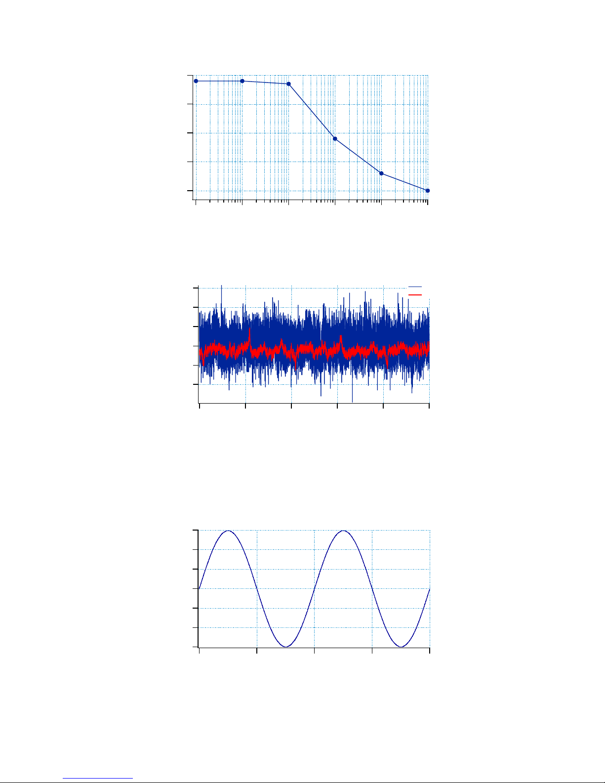
Figure 7. Rms output noise voltage versus capacitive load
Figure 8. Noise without output loading, and with the the 1µF capacitor box connected, plus
typical offset. The noise, as measured with a true rms voltmeter in a 1MHz bandwidth, is
48µV
rms
with no load, and 18µV
rms
with the 1µF load connected. The corresponding signal
bandwidths of the amplifier are DC – 100kHz and DC – 500Hz. The noise and offset may
appear to be slightly higher than shown here if the amplifier input is not differentially
connected to a low-impedance source.
Figure 9. Sine wave 300Vpp 1kHz
Capacitance (pF)
Rms output voltage noise (µV)
50
40
30
20
10
10
2
10
3
10
4
10
5
10
6
10
7
Time (ms)
Output voltage (mV)
-0.9
-0.8
-0.7
-0.6
-0.5
-0.4
50403020100
0pF
1uF
Time (ms)
Output voltage (V)
-150
-100
-50
0
50
100
150
2.01.51.00.50.0
Page 8
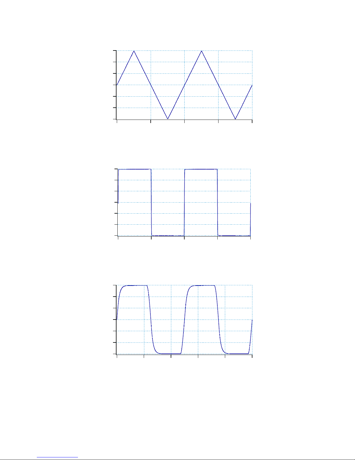
Figure 10. Triangle wave 300Vpp 1kHz
Figure 11. Square wave 300Vpp 1kHz
Figure 12. Square wave 300Vpp 20kHz
Time (ms)
Output voltage (V)
-150
-100
-50
0
50
100
150
2.01.51.00.50.0
Time (ms)
Output voltage (V)
-150
-100
-50
0
50
100
150
2.01.51.00.50.0
Time (µs)
Output voltage (V)
-150
-100
-50
0
50
100
150
100806040200
Page 9
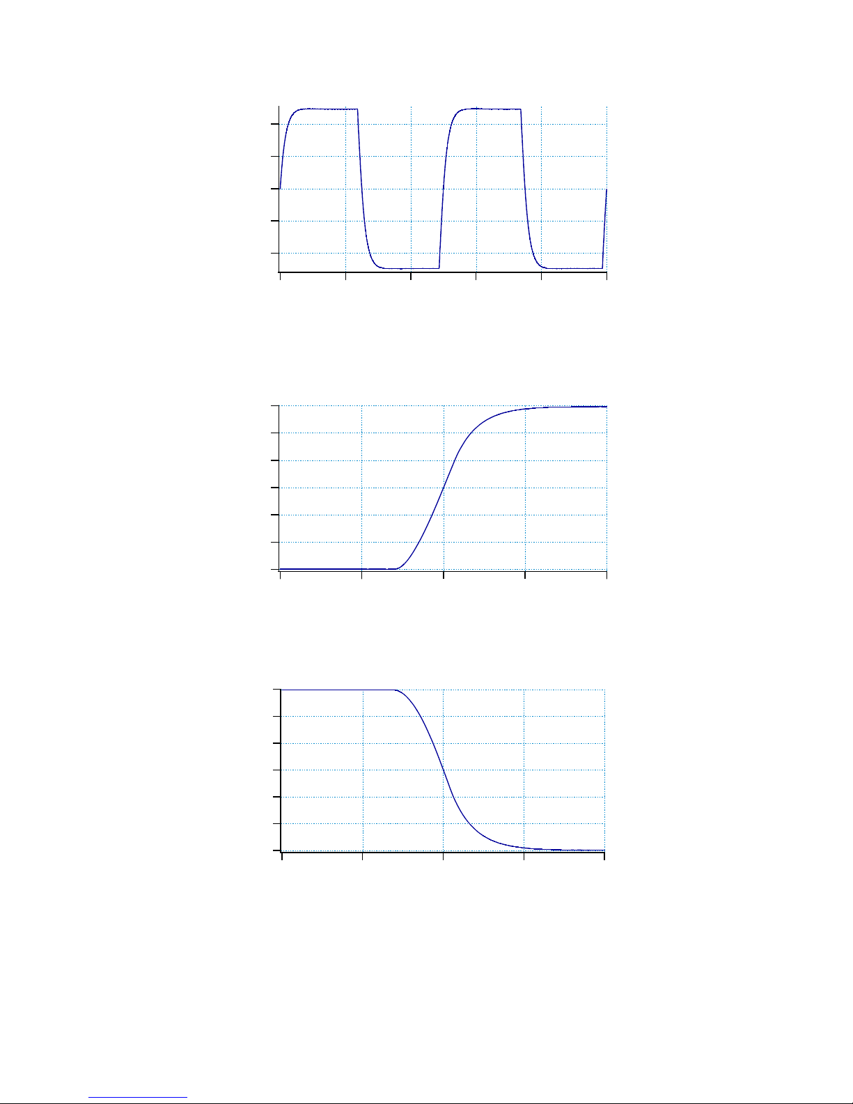
Figure 13. Square wave 1Vpp 20kHz (small signal response)
Figure 14a. 300Vpp step response 10-90%: up in 4.4µs
Figure 14b. 300Vpp step response 10-90%: down in 4.2µs
Time (µs)
Output voltage (V)
-0.4
-0.2
0.0
0.2
0.4
100806040200
Time (µs)
Output voltage (V)
-150
-100
-50
0
50
100
150
-10 -5 0 5 10
Time (µs)
Output voltage (V)
-150
-100
-50
0
50
100
150
-10 -5 0 5 10
Page 10
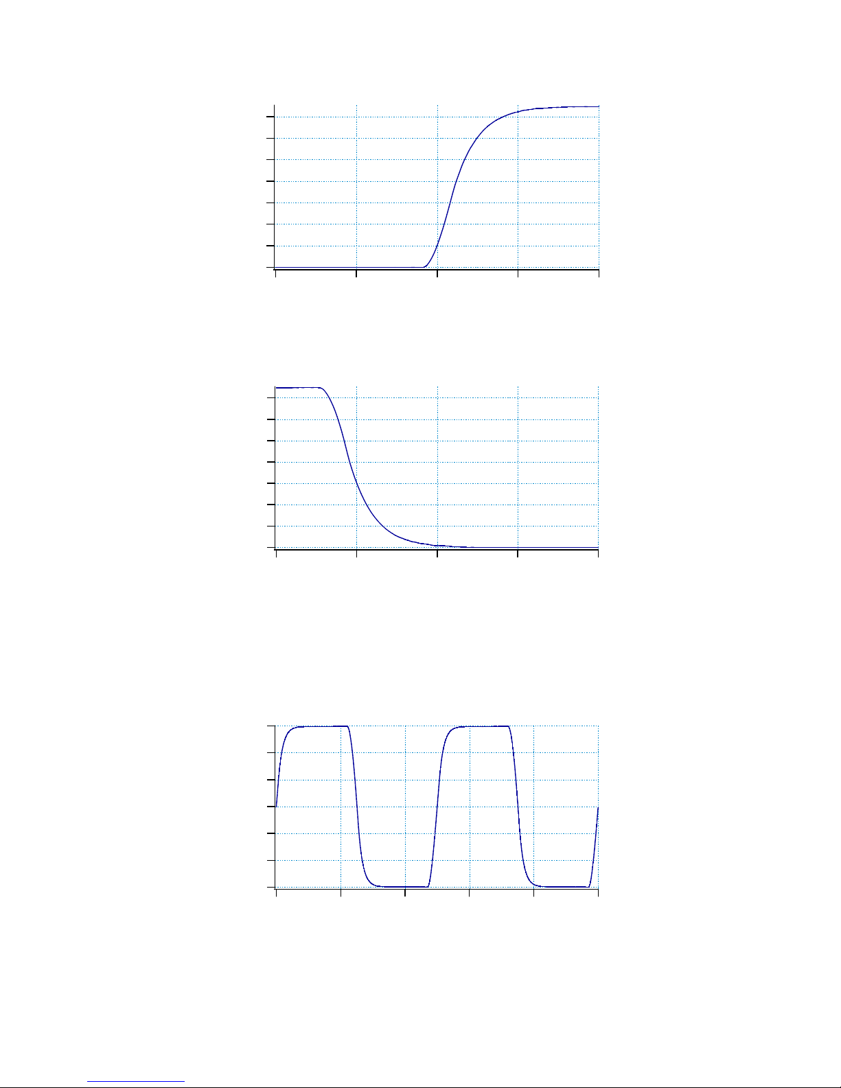
Figure 14c. 0 to 150V step response 10-90%: up in 3.5µs
Figure 14d. 150 - 0V step response 10-90%: down in 3.8µs
Figure 14. Unipolar and bipolar step response
Figure 15a. 0pF load
Time (µs)
Output voltage (V)
140
120
100
80
60
40
20
0
-10 -5 0 5 10
Time (µs)
Output voltage (V)
140
120
100
80
60
40
20
0
-10 -5 0 5 10
Time (µs)
Output voltage (V)
-150
-100
-50
0
50
100
150
100806040200
Page 11
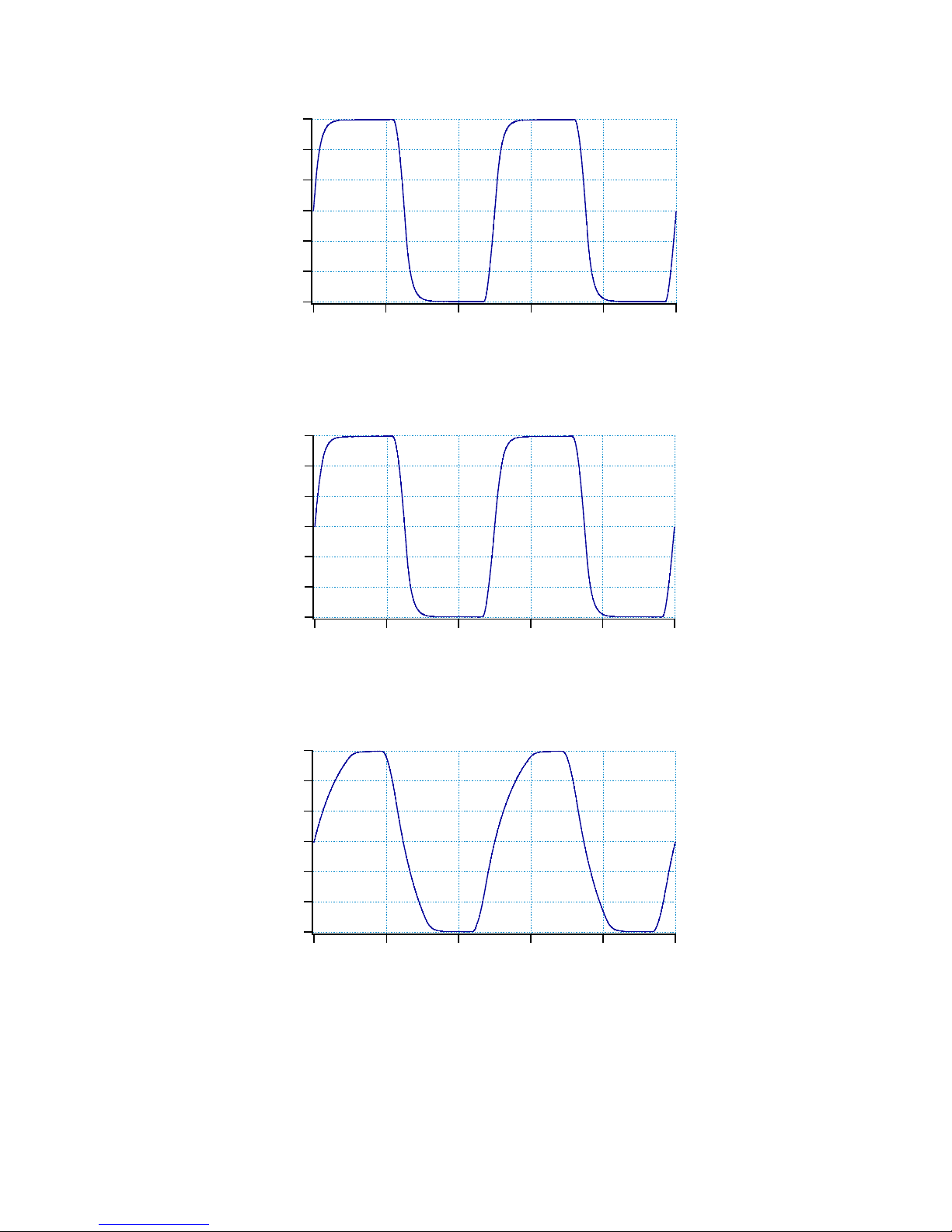
Figure 15b. 100pF load
!
Figure 15c. 1nF load
Figure 15d. 10nF load
Time (µs)
Output voltage (V)
-150
-100
-50
0
50
100
150
100806040200
Time (µs)
Output voltage (V)
-150
-100
-50
0
50
100
150
100806040200
Time (µs)
Output voltage (V)
-150
-100
-50
0
50
100
150
100806040200
Page 12
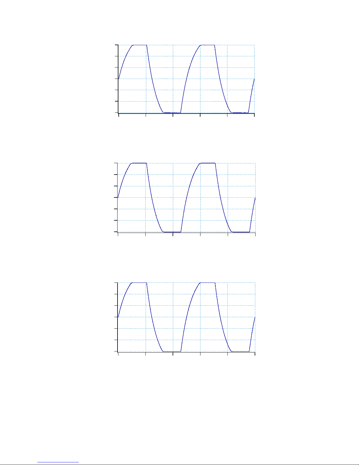
Figure 15e. 100nF load
Figure 15f. 1µF load
Figure 15g. 10µF load
Figure 15. 300Vpp square wave response under different capacitive loading conditions. The
275mA current limit limits the speed at which the capacitor can be charged. The bandwidth
adjustments of the amplifier with different capacitive loads preventing overshoot are clearly
visible. Note the difference of the horizontal timescale in the figures.
Time (ms)
Output voltage (V)
-150
-100
-50
0
50
100
150
1.00.80.60.40.20.0
Time (ms)
Output voltage (V)
-150
-100
-50
0
50
100
150
1086420
Time (ms)
Output voltage (V)
-150
-100
-50
0
50
100
150
100806040200
Page 13
Technical specifications
Amplification: precision 20.0x, fixed
Bandwidth: DC – 100kHz @ -3dB large signal bandwidth
Noise and offset: 50µV
rms
output noise typical without capacitor box, 20µV
rms
with capacitor
box connected to the output, 700µV offset typical
Output voltage: -175V to +175V
Current: 275mA typical with limiter
Slew rate: 80V/µs typical
Input impedance: 1kΩ // 100pF
Output impedance: 50Ω
Stability: stable with all capacitive and resistive loads, no overshoot > 5%
Power: 230V 50Hz AC, 140W or 115V 60 Hz AC, 140W
Mains fuse: 2x 800mA 250V slow blow (230V version) or 2x 1.6A 250V slow blow (115V
version)
Safety: Class I - requires mains power connector with protective earth
Overvoltage: Category II
Operating temperature: 15 – 30°C
Storage temperature: 0 – 60°C
Relative humidity: 30 – 70% non-condensing
Maximum usage height: 2000m
Dimensions: 52 x 165 x 300mm
Weight: 4.3kg
Country of origin: The Netherlands
Specifications may be subject to change
Harmonized standards
This product complies with the following
standards:
Safety: EN61010-1
EMC: EN61326
FCC: 47 CFR 15
WEEE and RoHS
Do not dispose of the WMA-200 amplifier
as standard waste, but bring it to a WEEE
electronic waste collection point. The
amplifier has been built in compliance with
the RoHS directive.
Warranty
Falco Systems products are guaranteed
against malfunction due to defects in
materials or workmanship for a period of 1
year from the date of shipment.
If a malfunction occurs during this period,
the product will be repaired or replaced
without charge. The product will be
returned to the customer prepaid.
The warranty does not apply to:
- Exterior finish or appearance
- Malfunction resulting from use or
operation of the product in other ways than
specified in the user manual
- Malfunctioning due to misuse or abuse of
the product
- Malfunctioning occurring after changes or
repairs have been made by anyone other
than Falco Systems.
To obtain warranty service, the customer
has to inform Falco Systems first via
[email protected] to receive further
instructions.
Falco Systems will not be liable for any
consequential damages, including, without
limitation, devices or equipment connected
to the product, injury to persons or
property or loss of use. See for more
details the Falco Systems Standard Terms
and Conditions of Sale, which can also be
obtained via [email protected].
Page 14

User manual version
User manual version: 1.3
Date: December 9, 2016
Falco Systems
Falco Systems
Remisestraat 1
2225 TH Katwijk aan Zee
The Netherlands
Tel. +31 (0)6 21840996
Fax. +31 (0)20 2031 445
Email: [email protected]
http://www.falco-systems.com
 Loading...