

Page 1
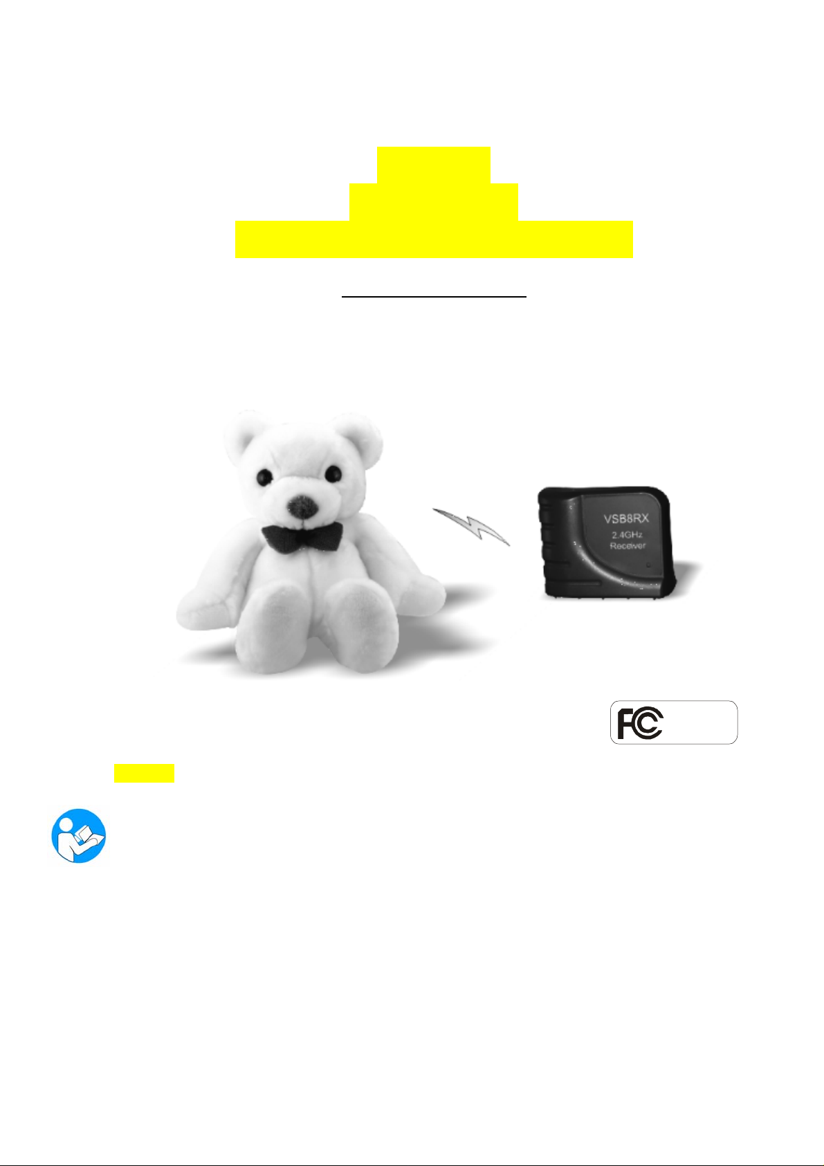
2.4 GHz
WIRELESS
SURVEILLANCE SYSTEM
Operating Instr u c t io n s
Te sted C o m p l y
With FCC Standards
Model # TBM-18
BEFORE OPERATING THIS PRODUCT, READ, UNDERSTAND,
AND FOLLOW THESE INSTRUCTIONS.
Be sure to save this booklet for future reference.
Page 2

IMPORTANT SAFETY INSTRUCTIONS
WARNING: TO AVOID THE RISK OF ELECTRICAL SHOCK, ALWAYS MAKE SURE THE
PRODUCT IS UNPLUGGED FROM THE ELECTRICAL OUTLET BEFORE RELOCATING,
SERVICING, OR CLEANING IT.
• This product is intended for non-c om m ercial, household use in providing video surveillance.
• This product is not a toy.
• Do not use the product for any other purpose.
• Keep the product out of the reach of children and pets. Children do not intend this product for
use.
• Do not leave the product unattended while it is in use. Always unplug the product from the
electrical outlet when it is not in use.
• Keep the product away from direct su nlight, open flame or other heat sources, humidity or
dusty environments.
• Do not block any ventilation openings. Install the product in accordance with the operating
instructions.
• Do not use attachments not recommended or sold by the product manufacturer, as a risk of fire,
electrical shock, or serious personal injury may result.
• Unplug the product from the electrical outlet prior to putting on or removing parts.
• Plug the product into a standard 120V AC electrical outlet.
• Do not use this product with a voltage converter.
• Do not plug or unplug the product from the electrical outlet with a wet hand, as a risk of
electrical shock exists.
• Disconnect the plug (do not pull on the Power Cord) from the electrical outlet.
• Do not allow the Power Cord to hang (i.e., over the edge of a table or counter) where it may be
tripped over or pulled.
• Protect the power cord from being walked on or pinched, particularly at plugs, convenience
receptacles, and the point where they exit the product.
• If using an extension cord, the marked electrical rating of the cord set or extension cord should
be at least as great as the electrical rating of the product.
• Never operate this product if it has a damaged Power Cord or plug, malfunctions or is not
working properly, has been dropped, or damaged. This product has no user-serv ic ea ble parts.
Do not attempt to examine or repair this product yourself. Only qualified service personnel
should perform any servicing.
• This product is intended for pers o nal, non-commercial, non-industrial, household use only.
Do not use outdoors.
1
Page 3
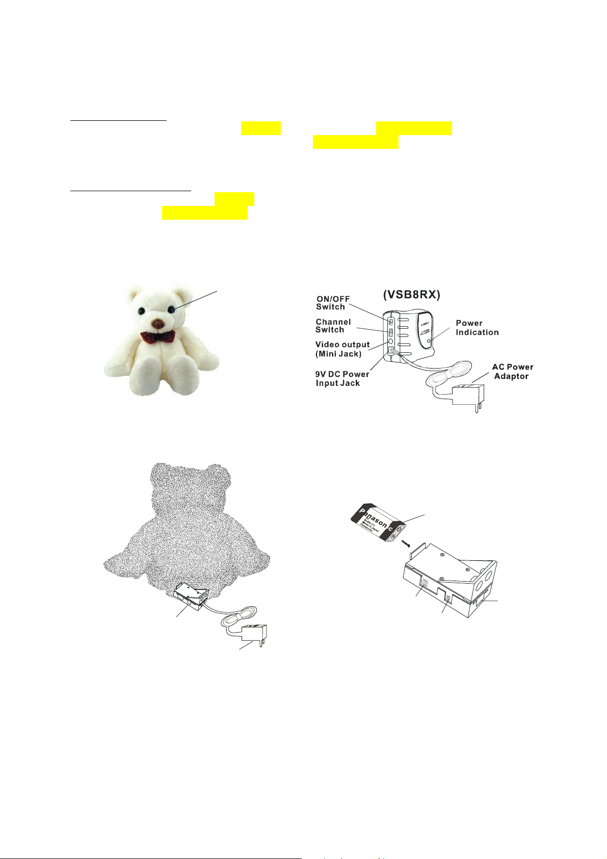
General Description:
The wireless, Bear Video Cam e ra (M o del #TBM-18) transmits video an d au d i o si gnals at a
frequency of 2.4 GHz to the video signal receiver (Model #VSB8RX). The vi de o signal receiver
outputs these signals via cable to your TV/VCR for monitoring and/or recording.
Equipment & accessories :
1. 1 x Bear Video Camera (Model # TBM-18)
2. 1 x Receiver (Model #VSB8RX)
Bear Camera
real eye
(right eye)
3. 1 x Audio/Video Cable
4. 2 x AC Power Adaptor (DC 9V)
9V Battery
(This part is
option for user)
DC-9V
Battery
room
and SW Bo ard
AC Power
Adaptor
Channel
Switch
Power
ON /OFF
DC-9V
2
Page 4

Installation:
Bear Video Camera (Model #TBM-18)
1. Power by either the Battery and DC power of the Bear video camera.
2. Position the video camera in the desired location.
NOTE: The transmission range of the Bear video camera at open side up to 150 ft. Real
distance is depends on its ope r a t ing environment. If you ar e r e ceiving poor video images f rom
the camera, try shortening the transmission range. Reposition and/or adjust the Bear video
camera if video transmissio n is bei ng de g raded by obstructions in its operating environment.
3. Select the desired transmission channel for the Bear video camera.
NOTE: The Model #TBM-18 Bear vide o camera has four (4) different transmission channels.
The Bear video camera has been set to transmit on CH 1 at the factory. Do not set and/or use
more than one (1) video camera on the same transmission channel in order to prevent signal
interference and unclear picture reception.
a. Remove the Channel Switch rubbe r grommet from the Bear video cam era (front) base.
(Refer to the diagram in the “Equipment and accessories” section.)
b. Use a small, blunted, pointed object to slide Channel Switch inside of the base opening,
as desired (Channel 1-4).
c. Securely reattach the Channel Switch rubber grommet onto the video camera base .
NOTE: Reference the “Rece iver (Model #VSB8RX)” section to update th e receiver
channel selection.
4. Open the Bear Camera Battery Zip put 9V battery in the battery ro om or connects the AC
Power Adaptor Jack end to the DC Input Jack end of the Bear Video camera.
5. Plug the AC Power Adaptor into a standard 120V AC electrical outlet.
6. Unplug the AC Power Adaptor from the electrical outlet w hen it is not in use or is left
unattended.
7. When DV9V Plug in Jack the Battery power will Auto switch off.
8. Please use 9 V ALKALINE Battery for battery source
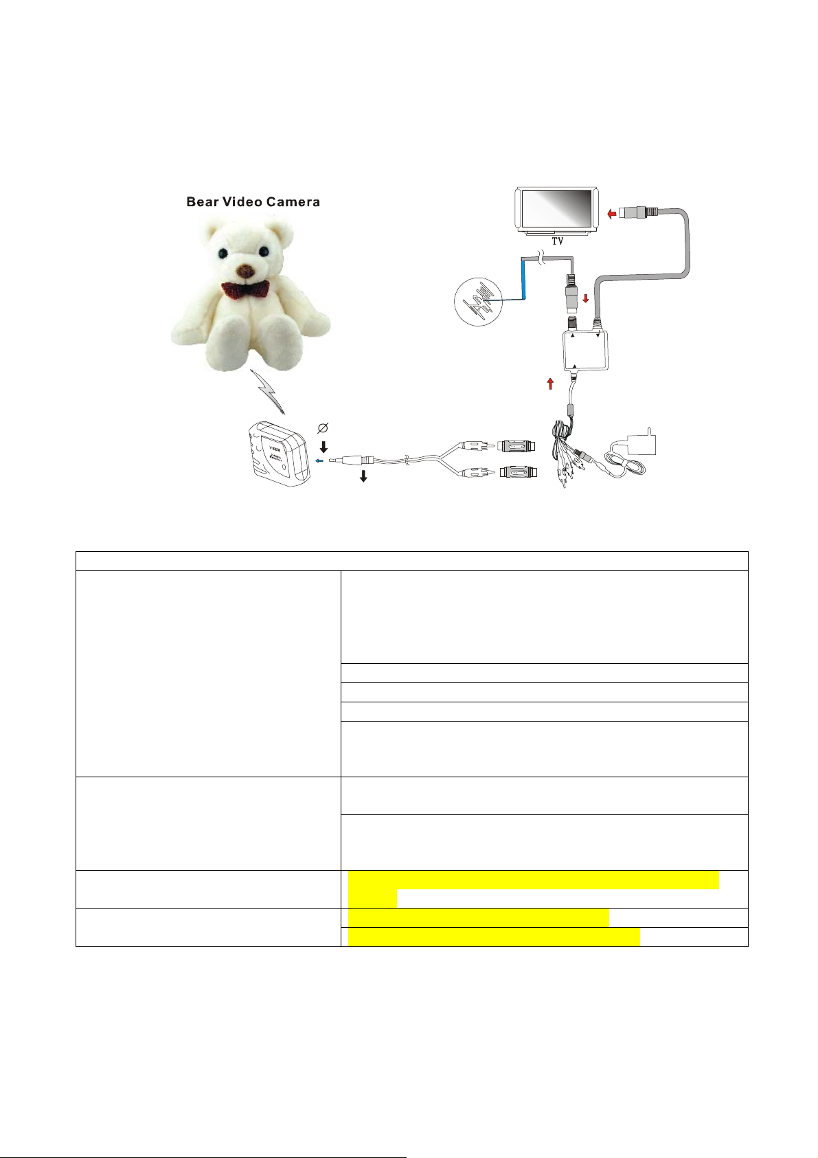
Receiver (Model #VSB8RX):
CAUTION: Make all of the necessary wire jack connections before plugging the AC Power
Adaptor into an electrical outlet, as a risk of electrical shock may exist. Keep away from water,
fire raindrop and high humidity
1. Insert the 3.5Ø cable plug into the A/V Output Ja ck of the receiver.
2. Insert the (yellow & white) cable plugs into the Video Input and Audio Input Jacks of your TV,
as appropriate.
3
Page 5

V
V
V
3.5
2.4GHz
Receiv er
(VSB8RX)
Plug
Vide o /Vid eo
Cable
TV
White
Plug
Audio
Input
Jack
Yellow
Plug
ideo
Input
Jack
2. Connect the AC Power Adaptor Jack end to the 9V DC Power Input Jack of the receiver.
3. Select/match the receiver channel to the desired video camera transmission channel.
4. Plug the AC Power Adaptor into a standard 120V AC electrical outlet.
5. Slide the ON/OFF Switch to the ON position.
6. Television Set configuration:
a. Turn on the power to the television set (TV).
b. Switch the TV channel to the VIDEO/LINE INPUT position.
c. Adjust the TV volume and picture, as desired.
7. Unplug the AC Power Adaptor from the electrical outlet w hen it is not in use or is left
unattended.
Video Recording Setup:
1. Follow the normal setup procedures for the Bear video camera and receiver.
2. Insert the (yellow & white) cable plugs into the Vide o In put and Audio Input Jacks of your
VCR, as appropriate.
3. Connect another video/audio cable from your VCR to the Video Input and Audio Input Jacks
of your television set.
3.5
Plug
ideo Cable
Wh ite
Plug
Yellow
Plug
TV
CR
Audio
Input
Jack
Video
Input
Jack
4
Page 6
Y
This Therefore unit is for those who TV set without A/V port
TV Ant enna
Input Signal
Selector
Coaxial
Cable
U
T
O
T
V
I
N
T
A
N
O
V
I
D
E
A
T
O
R
O
D
U
L
M
H
C
W
T
I
S
A
N
T
E
A
N
N
F
H
/
U
F
V
H
N
I
A
/
V
2.4GHz
Receiver
(VSB8R X)
3.5
Plug
Video /Video
Cable
ellow
Plug
White
Plug
Transfer
Connector
AC Adapter
TROUBLESHOOTING
No picture after turning on the TV.
Check the power supply:
• Ensure the both the transmitter and receiver are
properly connecte d an d set.
• Ensure both the transmitter and receiver power
indicators illuminate.
Ensure the video cable is well connected.
Ensure the TV channel is set to “Video.”
Set the receiver to the channel with the clearest signal.
Shorten the transmission range/distance between the
transmitter and receiver. Reposition and/or adjust the video
camera.
Unclear picture reception.
Check to ensure the receiver channel is set properly for the
desired video camera.
Shorten the transmission range/distance between the
transmitter and receiver. Reposition and/or adjust the Bear
camera. Check 9V Batter power is running out or not.
Unclear picture focus. The video camera is set at 4.9 ft (1.5 m) with a Free fo cus
feature.
Ensure the audio cable is well connected No Sound From TV
Check vol ume level is set properly for desire.
5
Page 7
TECHNICAL SPECIFICATIONS
Transmitter Receiver
Power Supply
(AC Power Adaptor)
Operating Temperature
Operating Environment
Channels Four (4)
Receiver Sensitivity -- -90dBm
Channel Space 18 MHz
Frequency Stability
A/V Modulation Type Frequency Modulation (FM)
Video Input Format NTSC -Video Output Format -- NTSC
Video Output Level
Net Weight 21.85 oz. (620g)
Dimensions 16.93 x 12.98 x 6.69 in (430x330x45mm)
NOTE: Changes or modifications no t expressly approved by the party res p o nsible for
compliance could void the user’s authority to operate the equipment.
This device complies with Part 15 of the FCC Rules. Operation is subject to the following
two conditions: (1) this device may not cause harmful interference; and (2) this device must
accept any interference received, including interference that may cause undesirable operation.
NOTE: This equipment has been tested and found to comply with the limits for a Class B
digital device, pursuant to Part 15 of the FCC Rules. These limits are designed to provide
reasonable protection against harmful interference in a residential installation. This
equipment generates, uses and can radiate radio frequency energy and, if not installed and
used in accordance with the instructions, may cause harmful interference to radio elevation
reception, which can be determined b y t urning the equipment off and on. The user is
encouraged to try to correct the interference by one or more of the following measur es:
• Reorient or relocate the receiving antenna.
• Increase the separation between the equipment and receiver.
• Connect the equipment into an outlet on a circuit different from that to which the receiver is
connected.
• Consult the dealer or an exper ienced radio/TV technician for help.
IMPORTANT INFORMATION REQUIRED BY THE FCC
Input: 110V AC
Output: 9V, 350 mA
32 ° F (0° C) ~ 126° F (45° C)
70 ° F (25° C) ~ 112° F (40° C)
(±) 250 KHz (±) 200 KHz
1Vp – p @ 75 Ω, > 38
dB
6
Page 8

LIMITED WARRANTY
This item is warranted to be free from defects in materials or workmanship for a period of one (1)
year from the original date of purchase under normal house hold use. Within the warranty period,
we will either repair or replace the product at our option. This warranty extends only to the
original retail purchaser, and e xcludes any damage to the prod uc t res u lting from accident or
misuse. The product is not warranted when used in a commercial or business environment.
The above warranty is complete and exclusive. The warrantor expressly disclaims liability for any
special, incidental, indi rect, or consequential da mages in connection with the purchase or use of
this product or costs over the or iginal purchase price.
Any implied warranties arising by operation of law shall be limited in duration to the terms of this
warranty.
This warranty gives you specific le ga l ri gh ts and you may have other rights, which vary by
jurisdiction.
Camera, Receiver and other
Components Made in Taiwan
AC Adaptors Made in China
Package in Taiwan
7
Page 9

2.4 GHz
WIRELESS
SURVEILLANCE SYSTEM
Operating Instr u c t io n s
Te sted C o m p l y
With FCC Standards
Model # TCM-30
BEFORE OPERATING THIS PRODUCT, READ, UNDERSTAND, AND
FOLLOW THESE INSTRUCTIONS.
Be sure to save this booklet for future reference.
Page 10

IMPORTANT SAFETY INSTRUCTIONS
WARNING: TO AVOID THE RISK OF ELECTRICAL SHOCK, ALWAYS MAKE SURE
THE PRODUCT IS UNPLUGGED FROM THE ELECTRICAL OUTLET BEFORE
RELOCATING, SERVICING, OR CLEANING IT.
• This product is intended for non-commercial, household use in providing video surveillance.
• This product is not a toy.
• Do not use the product for any other purpose.
• Keep the product out of the reach of children and pets. This product is not intended for use
by children.
• Do not leave the product unattended while it is in use. Always unplug the product from the
electrical outlet when it is not in use.
• Keep the product away from direct sunlight, open flame or other heat sources, h umidity or
dusty environments.
• Do not block any ventilation openin gs. I nsta ll the product in accordance with the operating
instructions.
• Do not use attachments not recommended or sold by the product manufacturer, as a risk of
fire, electrical shock, or serious pe rsonal injury may result.
• Unplug the product from the electrical outlet prior to putting on or removing parts.
• Plug the product into a standard 120V AC electrical outlet.
• Do not use this product with a voltage converter.
• Do not plug or unplug the product from the electrical outlet with a wet hand, as a risk of
electrical shock e x ists.
• Disconnect the plug (do not pull on the Power Cord) from the electrical outlet.
• Do not allow the Power Cord to hang (i.e., over the edge of a table or counter) where it may
be tripped over or pulled.
• Protect the power cord from being walke d o n or pin c hed, particularly at plugs, co n ve n ience
receptacles, and the point where they exit the product.
• If using an extension cord, the marked el ectrical rating of the cord set or ext e nsion cord
should be at least as great as the electrica l rating of the product.
• Never operate this product if it has a damaged Power Cord or plug, m a lfunctions or is not
working properly, has been dropped, or damaged. This product has no user-serviceable
parts. Do not attempt to examine or repair this product yourself. Only qualified service
personnel should perform any servicing.
• This product is intended for personal, non-commercial, non- in dustrial, household use only.
Do not use outdoors.
1
Page 11

V
Y
General Description:
The wireless, Clock Video Camera (Model # TCM-30) transmits video and audio signals at a
frequency of 2.4 GHz to the video signal receiver (Model #VSB8RX). The video signal
receiver outputs these signals via cable to your TV/VCR for monitoring and/or recording.
Equipment & accessories
1. 1 x ClockVideo Camera (Model # TCM-30 )
2. 1 x Receiver (Model #VSB8RX)
:
3. 1 x Video Cable
4. 2 x AC Power Adaptor (DC 9V)
Video Camera
hannel
Switch
TCM-30
Wireless
ideo Camera
ON/OFF
Switch
Clock
CH1 2 3 4
Battery
for Clock
Adaptor
AC Power
Wireless
Video Camer a
3.5
2.4GHz
Receiver
(VSB8RX)
Clock
Plug
Video Cable
TV Antenna
ellow
Plug
Input Signal
Selector
Transfer
Connector
T
N
I
T
A
N
D
I
E
O
V
L
U
A
T
O
R
O
M
D
W
C
I
T
H
N
N
E
S
T
A
A
N
U
H
/
H
F
V
N
I
V
/
A
Coaxial
Cable
T
U
O
V
F
AC Adapter
2
Page 12

V
V
Installation:
Clock Video Camera (Model #TCM-30)
1. Power by DC power of the Clock video camera.
2. Position the video camera in the desired location.
NOTE: The transmission ran ge of the Clock video camera at open side up to 150 ft. Real
distance is depends on its ope r a t ing environment. If you ar e r e ceiving poor video images f rom
the camera, try shortening the transmission range. Reposition and/or adjust the Clock video
camera if video transmissio n is bei ng de g raded by obstructions in its operating environment.
3. Select the desired transmission channel for the Clock video camera.
NOTE: The Model #TCM-30 Clock video camera has four (4) dif ferent transmission channels.
The Clock video camera has been set to transmit on CH 1 at the factory. Do not set and/or use
more than one (1) video camera on the same transmission channel in order to prevent signal
interference and unclear picture reception.
4. Cnnect the AC Power Adaptor Jack end to the DC Input Jack end of the Clock Video camera .
5. Plug the AC Power Adaptor into a standard 120V AC electrical outlet.
6. Unplug the AC Power Adaptor from the electrical outlet w hen it is not in use or is left
unattended.
Receiver (Model #VSB8RX):
CAUTION: Make all of the necessary wire jack connections before plugging the AC Power
Adaptor into an electrical outlet, as a risk of electrical shock may exist. Keep away from water,
fire raindrop and high humidity
1. Insert the 3.5Ø cable plug into the Video out Jack of the receiver.
2. Insert the (yellow) cable plugs into the Video Input Jack of your TV, as appropriate.
3.5
2.4GHz
Receiver
(VSB8RX)
Wireless Vid eo
Camera in the Clock
Plug
ideo Cable
TV
Yellow
Plug
ideo
Input
Jack
3
Page 13

V
V
g
2. Connect the AC Power Adaptor Jack end to the DC Power Input Jack of the receiver.
3. Select/match the receiver channel to the desired video camera transmission channel.
4. Plug the AC Power Adaptor into a standard 120V AC electrical outlet.
5. Slide the ON/OFF Switch to the ON position.
6. Television Set configuration:
a. Turn on the power to the television set (TV).
b. Switch the TV channel to the VIDEO/LINE INPUT position.
c. Adjust the TV volume and picture, as desired.
7. Unplug the AC Power Adaptor from the electrical outlet w hen it is not in use or is left
unattended.
Video Recording Setup:
1. Follow the normal setup procedures for the Clock video camera and receiver.
2. Insert the (yellow) cable plugs into the Video Input Jack of your VCR, as appropriate.
3. Connect another video cable from your VCR to the Video Input Jack of your television set.
Wireless Video Camera
in the Clock
No picture after turning on the TV.
TROUBLESHOOTING
3.5
TV
Plug
ideo Cable
CR
Audio
Input
Jack
Video
Input
Jack
Check the power supply:
• Ensure the both the transmitter and receiver are
properly connected and set.
• Ensure both the transmitter and receiver power
indicators illuminate.
Ensure the video cable is well connected.
Ensure the TV channel is set to “Video.”
Set the receiver to the channel with the clearest signa l .
Shorten the transmission range/distance between the
transmitter and receiver. Reposition and/or adjust the video
camera.
Yellow
Plu
4
Page 14

Unclear picture reception.
Unclear picture focus. The video camera is set at 4.9 ft (1.5 m) with a Free fo cus
TECHNICAL SPECIFICATIONS
Transmitter Receiver
Power Supply
(AC Power Adaptor)
Operating Temperature
Operating Environment
Channels Four (4)
A/V Modulation Type Frequency Modulation (FM)
Video Input Format NTSC -Video Output Format -- NTSC
Video Output Level
NOTE: Changes or modifications no t ex pressly approved by the party responsible for complia nce
could void the user’s authority t o o pe r ate the equipment.
This device complies with Part 15 of the FCC Rules. Operation is subject to the following two
conditions: (1) this device may not cause harmful interference; and (2) this device must accept any
interference received, includin g interference that may cause undesirable operation.
NOTE: This equipment has been tested and f o und to comply with the limits for a Class B digital
device, pursuant to Part 15 of the FCC Rules. These limits are design ed to provide reasonable
protection against harm ful interference in a residential inst allation. This equipment generates, uses and
can radiate radio frequency energy and, if not installed and used in accordance with the instructions,
may cause harmful interf erence to radio elevation reception, which can be determined by turning the
equipment off and on. The user is encouraged to try to correct the interference by one or more of the
following measures:
• Reorient or relocate the receiving antenna.
• Increase the separation between the equipment and receiver.
• Connect the equipment into an outlet on a circuit different from that to which the receiver is
connected.
• Consult the dealer or an experienced radio/TV technician for help.
IMPORTANT INFORMATION REQUIR E D B Y THE FCC
Check to ensure the receiver channel is set properly for the
desired video camera.
Shorten the transmission range/distance between the
transmitter and receiver. Reposition and/or adjust the Clock
camera. Check 9V Batter power is runnin g o u t or not.
feature.
Output: 9V, 350 mA
32 ° F (0° C) ~ 126° F (45° C)
70 ° F (25° C) ~ 112° F (40° C)
1Vp – p @ 75 Ω
5
Page 15

LIMITED WARRANTY
This item is warranted to be free from defects in materials or workmanship for a period of one (1)
year from the original date of purchase under normal hous ehold use. Within the warranty period,
we will either repair or replace the product at our option. This warranty extends only to the
original retail purchaser, and e xcludes any damage to the prod uc t res u lting from accident or
misuse. The product is not warranted when used in a commercial or business environment.
The above warranty is complete and exclusive. The warrantor expressly disclaims liability for any
special, incidental, indirect, or consequential da mages in connection with the purcha se or use of
this product or costs over the or iginal purchase price.
Any implied war r anties arising by operation of law s hall be limited in d uration to the terms of this
warranty.
This warranty gives you specific le ga l ri gh ts and you may have other rights, which vary by
jurisdiction.
Camera, Receiver and other
Components Made in Taiwan
AC Adaptors Made in China
Package in Taiwan
6
Page 16

2.4 GHz Jewel Box
Wireless Video Camera
Operating Instr u c t io n s
Te sted C o m p l y
With FCC Standards
Model # TJM-275
BEFORE OPERATING THIS PRODUCT, READ, UNDERSTAND,
AND FOLLOW THESE INSTRUCTIONS.
Be sure to save this booklet for future reference.
Page 17

IMPORTANT SAFETY INSTRUCTIONS
WARNING: TO AVOID THE RISK OF ELECTRICAL SHOCK, ALWAYS MAKE SURE
THE PRODUCT IS UNPLUGGED FROM THE ELECTRICAL OUTLET BEFORE
RELOCATING, SERVICING, OR CLEANING IT.
• This product is intended for non-commercial, household use in providing video surveillance.
• This product is not a toy.
• Do not use the product for any other purpose.
• Keep the product out of the reach of children and pets. This product is not intended for use
by children.
• Do not leave the product unattended while it is in use. Always unplug the product from the
electrical outlet when it is not in use.
• Keep the product away from direct sunlight, open flame or other heat sources, h umidity or
dusty environments.
• Do not block any ventilation openin gs. I nsta ll the product in accordance with the operating
instructions.
• Do not use attachments not recommended or sold by the product manufacturer, as a risk of
fire, electrical shock, or serious pe rsonal injury may result.
• Unplug the product from the electrical outlet prior to putting on or removing parts.
• Plug the product into a standard 120V AC electrical outlet.
• Do not use this product with a voltage converter.
• Do not plug or unplug the product from the electrical outlet with a wet hand, as a risk of
electrical shock e x ists.
• Disconnect the plug (do not pull on the Power Cord) from the electrical outlet.
• Do not allow the Power Cord to hang (i.e., over the edge of a table or counter) where it may
be tripped over or pulled.
• Protect the power cord from being walke d o n or pin c hed, particularly at plugs, co n ve n ience
receptacles, and the point where they exit the product.
• If using an extension cord, the marked el ectrical rating of the cord set or ext e nsion cord
should be at least as great as the electrica l rating of the product.
• Never operate this product if it has a damaged Power Cord or plug, m a lfunctions or is not
working properly, has been dropped, or damaged. This product has no user-serviceable
parts. Do not attempt to examine or repair this product yourself. Only qualified service
personnel should perform any servicing.
• This product is intended for personal, non-commercial, non- in dustrial, household use only.
Do not use outdoors.
1
Page 18

V
General Description:
The wireless, Jewel box Video Camera (Model #TJM-275) transmits video and audio signals
at a frequency of 2.4 GHz to the video signal receiver (Model #VSB8RX). The video signal
receiver outputs these signals via cable to your TV/VCR for monitoring and/or recording.
Equipment & accessories:
1. 1 x Jewel box Video Camera (Model #
TJM-275)
2. 1 x Receiver (Model #VSB8RX)
3. 1 x Video Cable
4. 2 x AC Power Adaptor (DC 9V)
Jewel Box Video Camera
y
r
e
t
t
a
B
V
9
m
o
o
r
Input Signal
Jewel Box
Video Camera
TV Antenna
Selector
A
A
Channel
Switch
D
C
9
V
I
N
AC Power
Adapter
ON/OFF
Switch
2.4GHz
Receiver
(VSB8RX)
3.5
Plug
ideo Cable
Yellow
Plug
Transfer
Connector
T
V
O
T
I
N
N
O
I
E
D
V
T
A
R
O
L
U
D
O
M
S
W
T
I
C
H
T
N
E
A
N
A
N
F
/
U
H
F
V
H
/
V
N
I
Coaxial
Cable
T
U
AC Adapter
2
Page 19

V
V
Installation:
Jewel box Video Camera (Model #TJM-275)
1. Power by either the Battery and DC power of the Jewel box video camera.
2. Position the video camera in the desired location.
NOTE: The transmission range of the Jewel box video camera at open side up to 150 ft. Real
distance is depends on its ope r a t ing environment. If you ar e r e ceiving poor video images f rom
the camera, try shortening the transmission range. Reposition and/or a djust the Jewel box
video camera if video transmissi on is being degraded by obstructi ons in its operating
environment.
3. Select the desired transmission channel for the Jewel box video camera.
NOTE: The Model #TJM-275 Jewel box video camera has four (4) different transmission
channels. The Jewel box vide o ca mera has been set to transmit on CH 1 at t he factory. Do not
set and/or use more than one (1) video camera on the same transmission channel in order to
prevent signal interference and unclear picture reception.
4. Connect DC Input Jack or connec t the AC Power Adaptor Jack end to the DC Input Jack end
of the Jewel box Video camera.
5. Plug the AC Power Adaptor into a standard 120V AC electrical outlet.
6. Unplug the AC Power Adaptor from the electrical outlet w hen it is not in use or is left
unattended.
Receiver (Model #VSB8RX):
CAUTION: Make all of the necessary wire jack connections before plugging the AC Power
Adaptor into an electrical outlet, as a risk of electrical shock may exist. Keep away from water,
fire raindrop and high humidity
1. Insert the 3.5Ø cable plug into the Video O utput Jack of the receiver.
2. Insert the (yellow ) cable plugs into the Video Inpu t Jack of your TV, as appropriate.
Jewel Box
Video Camera
3.5
2.4GHz
Receiver
(VSB8RX)
Plug
ideo Cable
TV
Audio
Input
Jack
Yellow
Plug
ideo
Input
Jack
3
Page 20

V
V
2. Connect the AC Power Adaptor Jack end to the DC Power Input Jack of the receiver.
3. Select/match the receiver channel to the desired video camera transmission channel.
4. Plug the AC Power Adaptor into a standard 120V AC electrical outlet.
5. Slide the ON/OFF Switch to the ON position.
6. Television Set configuration:
a. Turn on the power to the television set (TV).
b. Switch the TV channel to the VIDEO/LINE INPUT position.
c. Adjust the TV volume and picture, as desired.
7. Unplug the AC Power Adaptor from the electrical outlet w hen it is not in use or is left
unattended.
Video Recording Setup:
1. Follow the normal setup procedures for the Jewel box video camera and receive r.
2. Insert the (yellow) cable plugs into the Video Input Jack of your VCR, as appropriate.
3. Connect another video/audio cable from your VCR to the Video Input Jack of your television
set.
Jewel Box
Video Camera
TROUBLESHOOTING
No picture after turning on the TV.
Check the power supply:
Ensure the video cable is well connected.
Ensure the TV channel is set to “Video.”
Set the receiver to the channel with the clearest signa l .
Shorten the transmission range/distance between the
transmitter and receiver. Reposition and/or adjust the video
camera.
Unclear picture reception. Check to ensure the receiver channel is set properly for the
desired video camera.
3.5
TV
Plug
ideo Cable
CR
Audio
Input
Jack
Yellow
Plug
Video
Input
Jack
• Ensure the both the transmitter and receiver are
properly connected and set.
• Ensure both the transmitter and receiver power
indicators illuminate.
4
Page 21

Shorten the transmission range/distance between the
transmitter and receiver. Reposition and/or adjust the Jewel
box camera.
Unclear picture focus. The video camera is set at 4.9 ft (1.5 m) with a Free fo cus
feature.
TECHNICAL SPECIFICATIONS
Transmitter Receiver
Power Supply
(AC Power Adaptor)
Operating Temperature
Operating Environment
Channels Four (4)
A/V Modulation Type Frequency Modulation (FM)
Video Input Format NTSC -Video Output Format -- NTSC
Video Output Level
NOTE: Changes or modifications no t ex pressly approved by the party res ponsible for compliance
could void the user’s authority t o o pe r ate the equipment.
This device complies with Part 15 of the FCC Rules. Operation is subject to the following two
conditions: (1) this device may not ca use harmful interference; and (2) this de v ic e must accept any
interference received, including interferenc e that may cause undesirable operation.
NOTE: This equipment has been tested and found to comply with the lim its for a Class B digital
device, pursuant to Part 15 of the FCC Rules. These limits are designed to provide reasonable
protection against harmful interference in a residential installation. This equipment generates, uses
and can radiate radio frequency energy and, if not installed and used in accordance with the
instructions, may cause harmful interference to radio elevation reception, which can be determined
by turning the equipment off an d o n. The user is encouraged to try to correct the i nterference by
one or more of the following measures:
• Reorient or relocate the receiving antenna.
• Increase the separation between the equipment and receiver.
• Connect the equipment into an outlet on a circuit different from that to which the receiver is
connected.
• Consult the dealer or an experienced radio/TV technician for help.
IMPORTANT INFORMATION REQUIR E D B Y THE FCC
Output: 9V, 350 mA
32 ° F (0° C) ~ 126° F (45° C)
70 ° F (25° C) ~ 112° F (40° C)
1Vp – p @ 75 Ω
5
Page 22

LIMITED WARRANTY
This item is warranted to be free from defects in materials or workmanship for a period of one (1)
year from the original date of purchase under normal house hold use. Within the warranty period,
we will either repair or replace the product at our option. This warranty extends only to the
original retail purchaser, and e xcludes any damage to the prod uc t res u lting from accident or
misuse. The product is not warranted when used in a commercial or business environment.
The above warranty is complete and exclusive. The warrantor expressly disclaims liability for any
special, incidental, indi rect, or consequential da mages in connection with the purchase or use of
this product or costs over the or iginal purchase price.
Any implied warra nt ie s ar isi n g by opera t i o n of law shal l be li mited in duration to the term s of this
warranty.
This warranty gives you specific le ga l ri gh ts and you may have other rights, which vary by
jurisdiction.
Camera, Receiver and other
Components Made in Taiwan
AC Adaptors Made in China
Package in Taiwan
6
 Loading...