

Page 1
T Series Service Manual
Extra Heavy Duty, Grade 1 Cylindrical Lever Lock
H
T
V
S
Q
B
R
Page 2

Table of Contents
Table of Contents
Introduction ............................................................... iii
Lock Assembly Index ................................................. 1
Chassis Assemblies ................................................... 3
Trim Assemblies ....................................................... 27
Standard Cylinders .................................................. 41
Falcon Complete Standard Cylinders ..................... 41
Standard Cylinder Options ...................................... 41
Standard Cylinder Tailpieces ................................... 41
Cylinders ................................................................... 41
Competitor Keyway Compatibility ............................ 42
IC Cylinders .............................................................. 42
Falcon Complete IC Cylinders ................................ 42
IC Cylinder Options ................................................. 43
IC Cylinder Tailpieces .............................................. 43
Competitor IC Compatibility .................................... 43
Inserts and Spindles ................................................ 44
Inside Inserts and Spindles ..................................... 44
Outside Inserts and Spindles .................................. 45
Levers ........................................................................ 46
Closed Levers ......................................................... 46
Open Levers ............................................................ 46
SFIC/IC Levers ........................................................ 47
Spring Cage Replacement Kits ............................... 47
Latches and Accessories ........................................ 48
Levers ........................................................................ 48
Grade 1 Latches...................................................... 48
Grade 2 Latches...................................................... 48
Accessories ............................................................. 49
Strikes and Dust Boxes ........................................... 50
Strikes ..................................................................... 50
Dust Boxes .............................................................. 50
Preparation and Installation .................................... 51
Installation Template ............................................... 51
Tailpiece Installation ................................................ 51
Installation Instructions ........................................... 52
Spring Cage Replacement Installation .................... 58
Warranty .................................................................... 59
T-Series Service Manual
ii
Page 3
Introduction
Introduction
This manual contains a complete listing of T-Series (Grade 1) cylindrical lock parts and assemblies manufactured by
the Falcon Lock Company. This edition lists components of T-Series locks manufactured after July 2007.
Exploded views of each lock chassis and trim assemblies are provided with an accompanying chart to identify parts
for replacement purposes. In addition, this manual provides general cylinder information, many auxiliary components
of the T-Series cylindrical locks and installation instructions.
Standard Features*
Certifications ANSI A156 .2, Series 4000, Grade 1, UL Listed for 3-hour fire door.
Latch
Strike
Backset
Cylinder 6-Pin solid brass, keyed 5-pin, Falcon G keyway, keyed different (KD)
Door Range
Keys Two nickel silver cut keys per lock, keyed 5-pin, Falcon G keyway
* Locks are furnished with standard features unless otherwise specified.
156” x 256M”, Square corner faceplate, 1” housing diameter, 56O” throw.
56M” x 4(6”, ANSI, Square corner, no box.
26M”
16M” – 256” standard
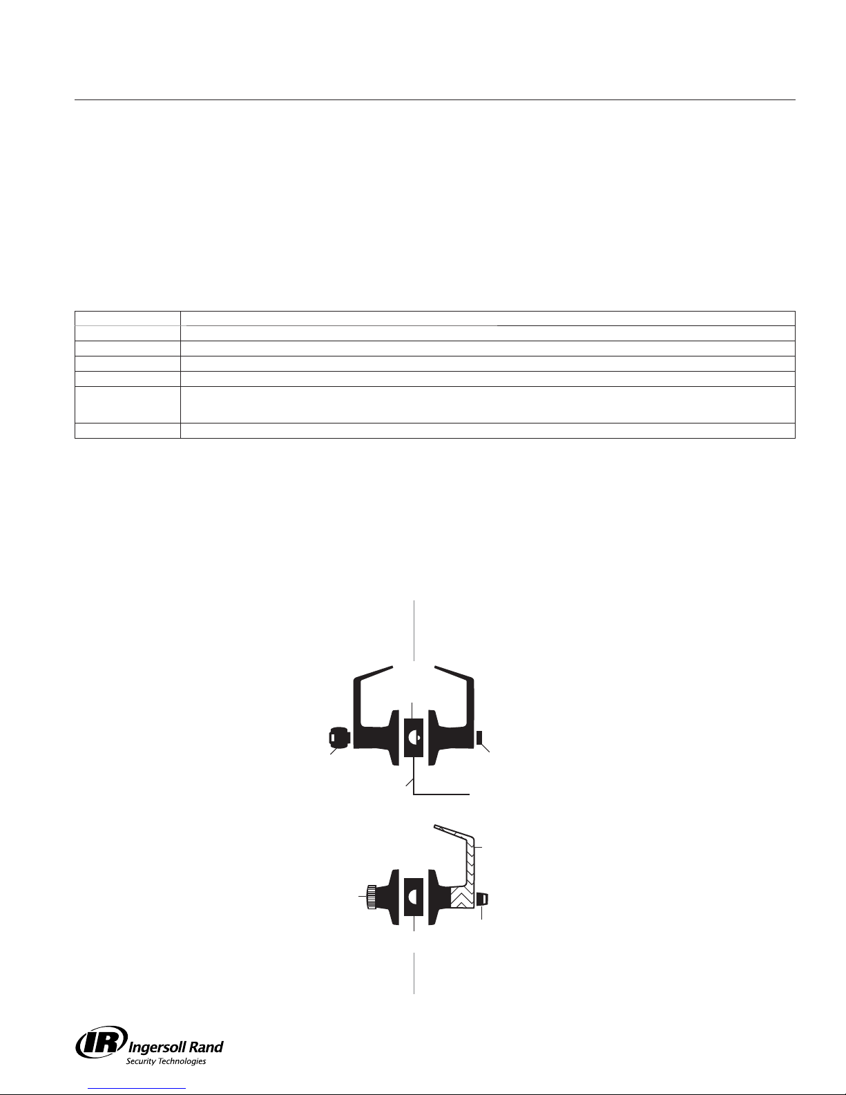
Lock Assembly Drawing Index
The Lock Assembly Drawing Index provides visual representations and textual descriptions of available functions.
Page numbers for full trim and chassis drawings are referenced.
Outside Inside
Deadlatch
Key
Electrified
Knurled Knob
Springlatch
Push button
Fixed Lever
Turn/push button
iii
T-Series Service Manual
Page 4
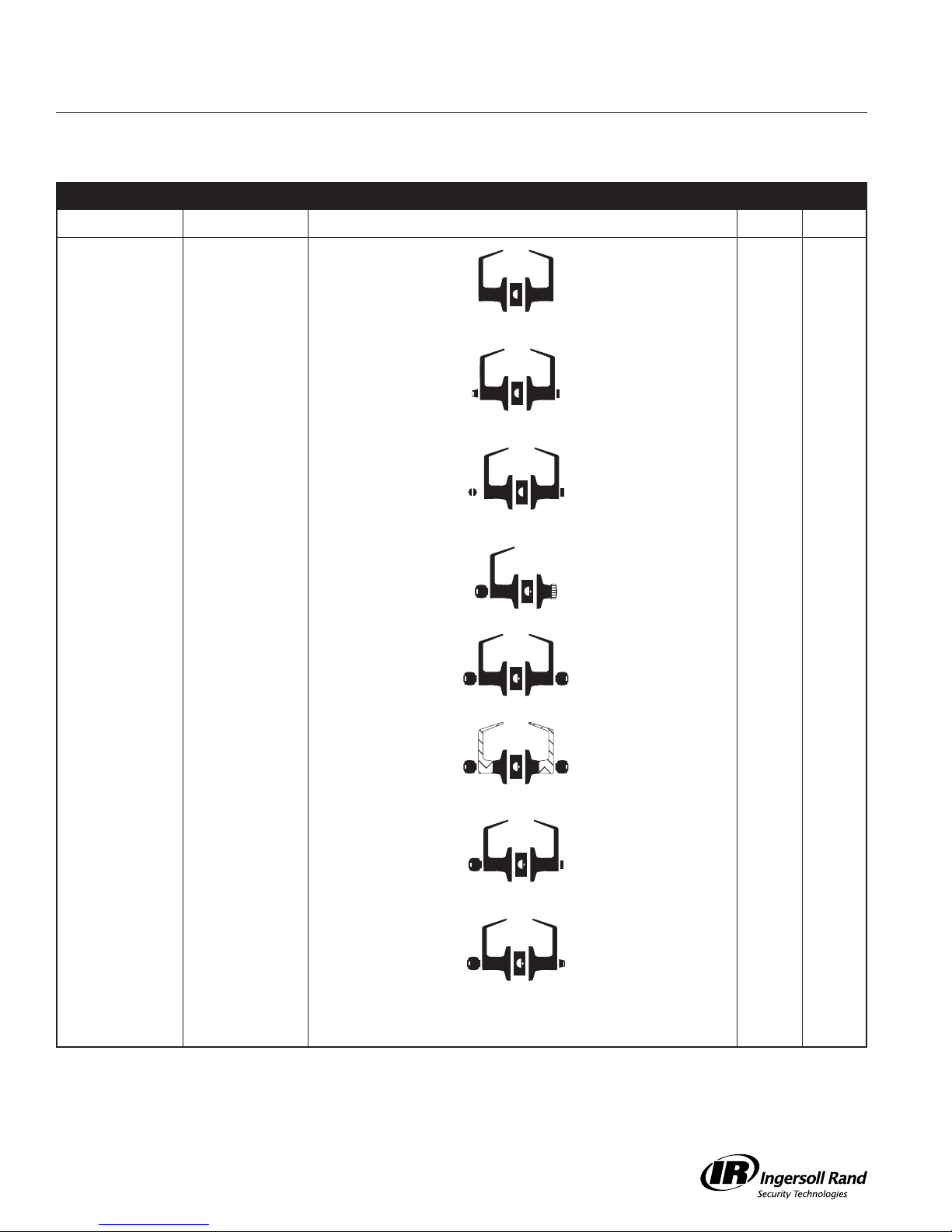
Lock Assembly Index
Lock Assembly Index
Function ANSI A156.2, 1996, Series 4000, Grade 1 Trim Chassis
FALCON ANSI DESCRIPTION OUTSIDE FUNCTION INSIDE FUNCTION
T101 F75 Passage/Closet
Latch
T291 Privacy Hospital
Lock
T301 F76 Privacy Lock
T351 Closet Lock
T381 F88 Classroom
Security Lock
Lever is always unlocked. Lever is always unlocked
Unlocked from outside
by turning emergency
turn-button.
Can be opened from
outside with small
screwdriver or
emergency release tool.
Can be locked with key. Knurled knob free for
Outside lever locked or
unlocked by key in either
lever.
and is always free for
immediate egress.
Push-button locks
outside lever. Turning
inside lever or closing
door releases button.
Inside lever is always
free for immediate egress.
Push-button locks
outside lever. Turning
inside lever or closing
door releases button.
Inside lever is always
free for immediate egress.
immediate egress unless
outside lever locked with
key.
Key locks or unlocks
outside lever. Inside lever
is always unlocked and is
always free for
immediate egress.
27 3
28 4
29 4
30 5
6 (IC)
31 7
8 (IC)
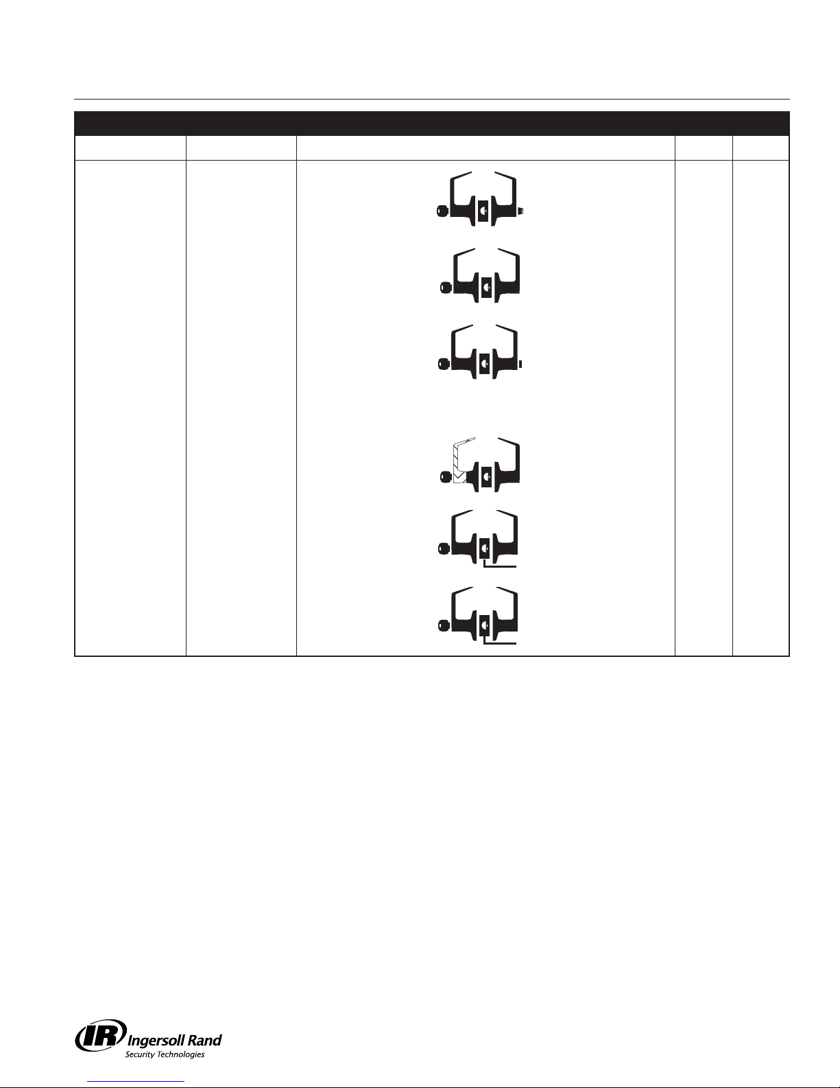
T411 F87 Asylum Lock
T501 F82 Entry Lock
T511 F109 Entry/Office Lock
NOTE: Any function with deadlatch locks latchbolt when door is closed.
Lever is fixed. Entrance
by key only.
Lever is
unlocked with key
when push-button
is pushed.
Key retracts latch when
button pushed and
turned. Lever is
unlocked with key
when push-button
is pushed.
Lever is fixed. Exit by
key only.
Push-button locks
outside lever. Turning
inside lever releases
button. Inside lever is
always free for immediate
egress.
Turn/push-button: pushing
and turning button locks
outside lever until manually
unlocked. Push-button:
pushing button locks
outside lever until unlocked
by turning inside lever.
Inside always free for
immediate egress.
32 9
10 (IC)
33 11
12 (IC)
34 13
14 (IC)
T-Series Service Manual
1
Page 5
Lock Assembly Index
Function ANSI A156.2, 1996, Series 4000, Grade 1 Trim Chassis
FALCON ANSI DESCRIPTION OUTSIDE FUNCTION INSIDE FUNCTION
T521 F81 Office Lock
T561 F84 Classroom Lock
T571 F90 Dormitory Lock
T581 F86 Storeroom Lock
T851 Storeroom Lock
(Electrified – Fail
Safe)
Key retracts latch when
button turned.
Outside lever locked or
unlocked by key.
Locked or unlocked
by key. When locked
by key it can only be
unlocked by key.
Lever is fixed. Entrance
by key only.
Lever is continuously
locked electrically.
Unlocked by switch or
power failure. When
locked, key retracts latch.
Turning button locks
outside lever until manually
unlocked. Inside always
free for immediate
egress.
Inside lever is always
unlocked and always
free for immediate
egress.
Push-button locks
outside lever. Turning
lever or closing door
releases button.
Inside lever is always
unlocked and is always
free for immediate
egress.
Inside lever is always
unlocked and is always
free for immediate
egress.
Inside lever is always
unlocked and is always
free for immediate
egress.
35 15
16 (IC)
36 17
18 (IC)
37 19
20 (IC)
38 21
22 (IC)
39 23
24 (IC)
T881 Storeroom Lock
(Electrified – Fail
Secure)
NOTE: Any function with deadlatch locks latchbolt when door is closed.
Lever is continuously
locked mechanically until
unlocked by electric
current. When locked,
key retracts latch.
Inside lever is always
unlocked and is always
free for immediate
egress.
40 25
26 (IC)
2
T-Series Service Manual
Page 6

Chassis Assemblies
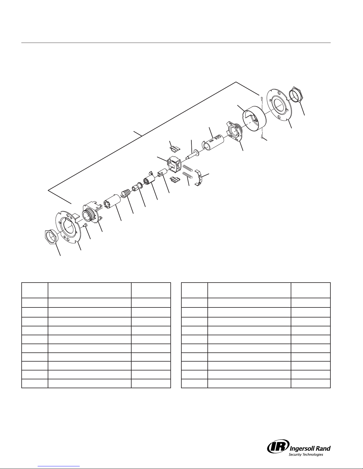
T101
Passage Latchset
12
1
2
8 (2)
6
14
7
13 (2)
11
10
9 (2)
6
5
4
3
2
Call Out
Number Description Part Number
1 Chassis Assembly, T101 A30761-000-00 8 Retractor Insert (2) 022986-001-50
2 Flanged Nut (2) 030726-000-30 9 Retractor Spring (2) 022108-001-60
3 Outer Mounting Plate 030712-001-30 10 Retractor Spring Retainer 022112-000-30
4
#8-32 x 6” Self Tap Screw
5 Hub and Housing Assembly A30746-000-00 12 Housing Case 022114-000-30
6 Spindle 030733-000-55 13 Cotter Pin (2) 002893-000-60
7 Retractor 022106-002-55 14 Inner Mounting Plate 030712-000-30
031533-006-30 11 Hub and Plate Assembly A30747-000-00
Call Out
Number Description Part Number
T-Series Service Manual
3
Page 7

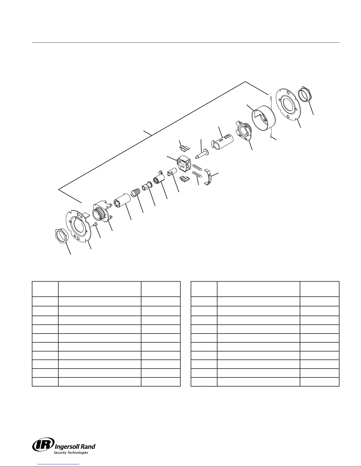
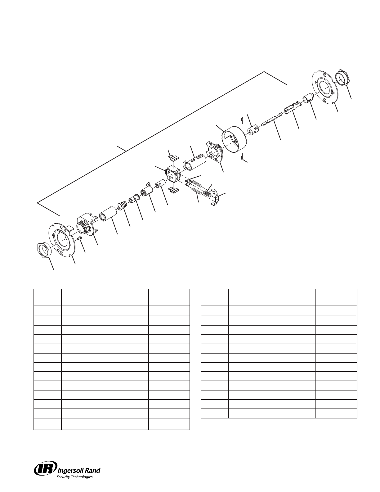
T291/T301
Privacy Hospital Lock
Chassis Assemblies
2
22
12
25
24
1
8 (2)
6
23
14
7
20
11
13 (2)
21
10
19
9 (2)
18
17
16
15
5
4
3
2
Call Out
Number Description Part Number
1 Chassis Assembly, T291/T301 A30765-000-00 14 Inner Mounting Plate 030712-000-30
2 Flanged Nut (2) 030726-000-30 15 Spindle, 1 Ear, Outer 030732-005-30
3 Outer Mounting Plate 030712-001-30 16 Clutch Spring 030709-000-60
4
#8-32 x 6” Self Tap Screw
5 Hub and Housing Assembly A30746-000-00 18 Key Spindle STD 030718-000-30
6 Spindle 030733-000-55 19 Push Actuator 030711-000-30
7 Retractor 022106-002-55 20 Slide Catch 022105-000-30
8 Retractor Insert (2) 022986-001-50 21 Slide Catch Spring 012107-001-60
9 Retractor Spring (2) 022108-001-60 22 Push Button Sleeve 022134-000-50
10 Retractor Spring Retainer 022112-000-30 23 Dogging Bar 030722-000-30
11 Hub and Plate Assembly A30747-000-00 24 Push/Turn Button Mount 030731-000-30
12 Housing Case 022114-000-30 25 Push Button Cap 030728-000*
13 Cotter Pin (2) 002893-000-60
031533-006-30 17 Clutch Driver 030716-001-30
Call Out
Number Description Part Number
4
T-Series Service Manual
Page 8

Chassis Assemblies
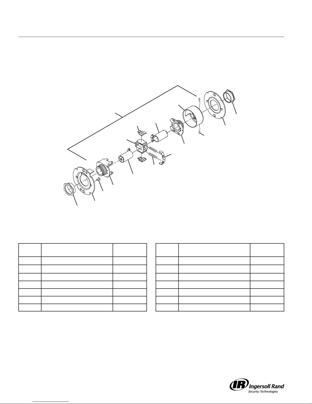
T351
Closet Lock
12
1
2
8 (2)
6
14
7
13 (2)
11
10
9 (2)
26
5
4
3
2
Call Out
Number Description Part Number
1 Chassis Assembly, T351/T561 A30758-000-00 9 Retractor Spring (2) 022108-001-60
2 Flanged Nut (2) 030726-000-30 10 Retractor Spring Retainer 022112-000-30
3 Outer Mounting Plate 030712-001-30 11 Hub and Plate Assembly A30747-000-00
4
#8-32 x 6” Self Tap Screw
5 Hub and Housing Assembly A30746-000-00 13 Cotter Pin (2) 002893-000-60
6 Spindle 030733-000-55 14 Inner Mounting Plate 030712-000-30
7 Retractor 022106-002-55 26 Key Spindle Assembly, STD A30780-000-30
8 Retractor Insert (2) 022986-001-50
031533-006-30 12 Housing Case 022114-000-30
Call Out
Number Description Part Number
T-Series Service Manual
5
Page 9

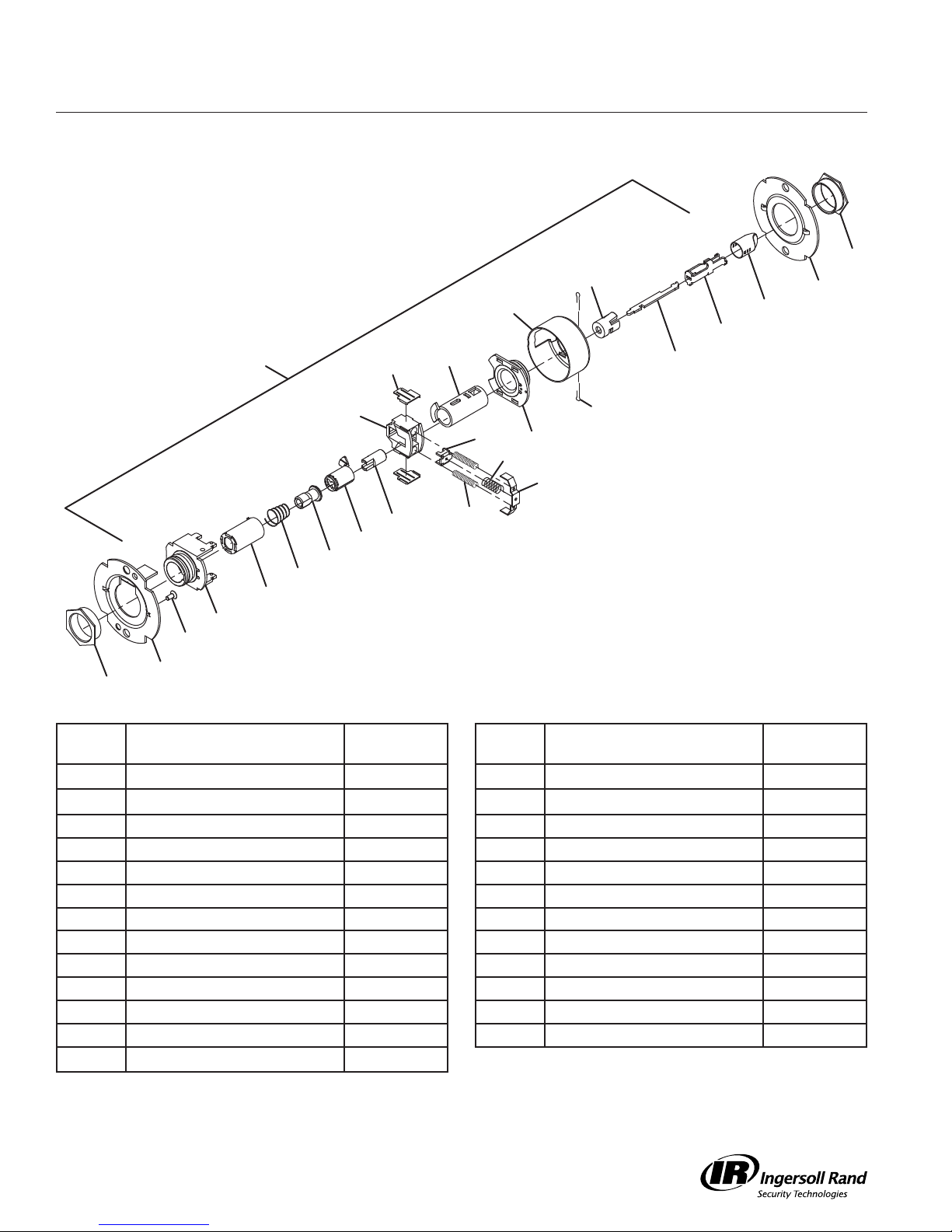
T351
Closet Lock – IC
Chassis Assemblies
12
1
2
14
8 (2)
6
7
13 (2)
11
10
9 (2)
27
5
4
3
2
Call Out
Number Description Part Number
1 Chassis Assembly, T351/T561-ICA30758-001-00 9 Retractor Spring (2) 022108-001-60
2 Flanged Nut (2) 030726-000-30 10 Retractor Spring Retainer 022112-000-30
3 Outer Mounting Plate 030712-001-30 11 Hub and Plate Assembly A30747-000-00
4
#8-32 x 6” Self Tap Screw
5 Hub and Housing Assembly A30746-000-00 13 Cotter Pin (2) 002893-000-60
6 Spindle 030733-000-55 14 Inner Mounting Plate 030712-000-30
7 Retractor 022106-002-55 27 Key Spindle Assembly, IC A30780-001-30
8 Retractor Insert (2) 022986-001-50
031533-006-30 12 Housing Case 022114-000-30
Call Out
Number Description Part Number
6
T-Series Service Manual
Page 10
Chassis Assemblies
T381
Classroom Security Lock
12
28
2
1
8 (2)
30
14
13 (2)
7
11
10
9 (2)
19
18
17
16
15
5
4
3
2
Call Out
Number Description Part Number
1 Chassis Assembly, T381 A30767-000-00 12 Housing Case 022114-000-30
2 Flanged Nut (2) 030726-000-30 13 Cotter Pin (2) 002893-000-60
3 Outer Mounting Plate 030712-001-30 14 Inner Mounting Plate 030712-000-30
4
#8-32 x 6” Self Tap Screw
5 Hub and Housing Assembly A30746-000-00 16 Clutch Spring 030709-000-60
7 Retractor 022106-002-55 17 Clutch Driver 030716-001-30
8 Retractor Insert (2) 022986-001-50 18 Key Spindle STD 030718-000-30
9 Retractor Spring (2) 022108-001-60 19 Push Actuator 030711-000-30
10 Retractor Spring Retainer 022112-000-30 28 IS Key Spindle Assembly, STD A30913-000-00
11 Hub and Plate Assembly A30747-000-00 30 Connecting Rod 030734-000-30
031533-006-30 15 Spindle, 1 Ear, Outer 030732-005-30
Call Out
Number Description Part Number
T-Series Service Manual
7
Page 11
T381
Classroom Security Lock – IC
Chassis Assemblies
12
29
2
1
8 (2)
30
14
13 (2)
7
11
10
9 (2)
19
31
17
16
15
5
4
3
2
Call Out
Number Description Part Number
1 Chassis Assembly, T381 A30767-001-00 12 Housing Case 022114-000-30
2 Flanged Nut (2) 030726-000-30 13 Cotter Pin (2) 002893-000-60
3 Outer Mounting Plate 030712-001-30 14 Inner Mounting Plate 030712-000-30
4
#8-32 x 6” Self Tap Screw
5 Hub and Housing Assembly A30746-000-00 16 Clutch Spring 030709-000-60
7 Retractor 022106-002-55 17 Clutch Driver 030716-001-30
8 Retractor Insert (2) 022986-001-50 19 Push Actuator 030711-000-30
9 Retractor Spring (2) 022108-001-60 29 IS Key Spindle Assembly, IC A30913-001-00
10 Retractor Spring Retainer 022112-000-30 30 Connecting Rod 030734-000-30
11 Hub and Plate Assembly A30747-000-00 31 Key Spindle, IC 030718-001-30
031533-006-30 15 Spindle, 1 Ear, Outer 030732-005-30
Call Out
Number Description Part Number
8
T-Series Service Manual
Page 12
Chassis Assemblies
T411
Asylum Lock
12
1
2
8 (2)
32
14
7
13 (2)
11
10
9 (2)
32
5
4
3
2
Call Out
Number Description Part Number
1 Chassis Assembly, T411 A30769-000-00 9 Retractor Spring (2) 022108-001-60
2 Flanged Nut (2) 030726-000-30 10 Retractor Spring Retainer 022112-000-30
3 Outer Mounting Plate 030712-001-30 11 Hub and Plate Assembly A30747-000-00
4
#8-32 x 6” Self Tap Screw
5 Hub and Housing Assembly A30746-000-00 13 Cotter Pin (2) 002893-000-60
7 Retractor 022106-002-55 14 Inner Mounting Plate 030712-000-30
8 Retractor Insert (2) 022986-001-50 32 Spindle, 2 Ear, STD 030732-000-30
031533-006-30 12 Housing Case 022114-000-30
Call Out
Number Description Part Number
T-Series Service Manual
9
Page 13

T411
Asylum Lock – IC
Chassis Assemblies
12
1
2
14
8 (2)
33
7
13 (2)
11
10
9 (2)
33
5
4
3
2
Call Out
Number Description Part Number
1 Chassis Assembly, T411-IC A30769-001-00 9 Retractor Spring (2) 022108-001-60
2 Flanged Nut (2) 030726-000-30 10 Retractor Spring Retainer 022112-000-30
3 Outer Mounting Plate 030712-001-30 11 Hub and Plate Assembly A30747-000-00
4
#8-32 x 6” Self Tap Screw
5 Hub and Housing Assembly A30746-000-00 13 Cotter Pin (2) 002893-000-60
7 Retractor 022106-002-55 14 Inner Mounting Plate 030712-000-30
8 Retractor Insert (2) 022986-001-50 33 Spindle, 2 Ear, IC 030732-001-30
031533-006-30 12 Housing Case 022114-000-30
Call Out
Number Description Part Number
10
T-Series Service Manual
Page 14

Chassis Assemblies
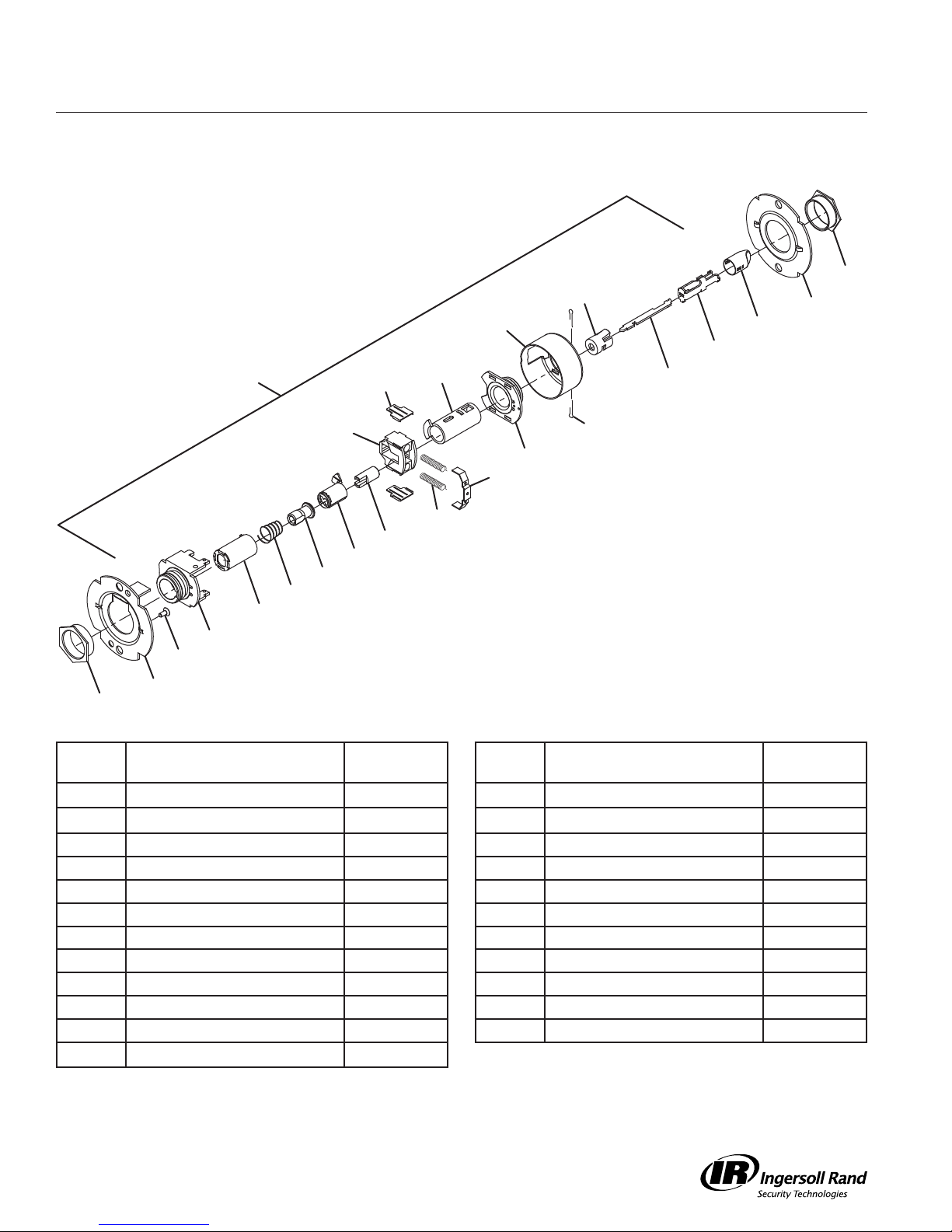
T501
Entry Lock
2
22
14
12
25
24
1
8 (2)
6
23
7
34
11
13 (2)
21
10
19
9 (2)
18
17
16
15
5
4
3
2
Call Out
Number Description Part Number
1 Chassis Assembly, T501 A30773-000-00 14 Inner Mounting Plate 030712-000-30
2 Flanged Nut (2) 030726-000-30 15 Spindle, 1 Ear, Outer 030732-005-30
3 Outer Mounting Plate 030712-001-30 16 Clutch Spring 030709-000-60
4
#8-32 x 6” Self Tap Screw
5 Hub and Housing Assembly A30746-000-00 18 Key Spindle STD 030718-000-30
6 Spindle 030733-000-55 19 Push Actuator 030711-000-30
7 Retractor 022106-002-55 21 Slide Catch Spring 012107-001-60
8 Retractor Insert (2) 022986-001-50 22 Push Button Sleeve 022134-000-50
9 Retractor Spring (2) 022108-001-60 23 Dogging Bar 030722-000-30
10 Retractor Spring Retainer 022112-000-30 24 Push/Turn Button Mount 030731-000-30
11 Hub and Plate Assembly A30747-000-00 25 Push Button Cap 030728-000*
12 Housing Case 022114-000-30 34 Short Slide Catch 022104-000-30
13 Cotter Pin (2) 002893-000-60
031533-006-30 17 Clutch Driver 030716-001-30
Call Out
Number Description Part Number
T-Series Service Manual
11
Page 15

T501
Entry Lock – IC
Chassis Assemblies
2
22
12
25
24
1
8 (2)
6
23
14
7
34
11
13 (2)
21
10
19
9 (2)
31
17
16
15
5
4
3
2
Call Out
Number Description Part Number
1 Chassis Assembly, T501-IC A30773-001-00 14 Inner Mounting Plate 030712-000-30
2 Flanged Nut (2) 030726-000-30 15 Spindle, 1 Ear, Outer 030732-005-30
3 Outer Mounting Plate 030712-001-30 16 Clutch Spring 030709-000-60
4
#8-32 x 6” Self Tap Screw
5 Hub and Housing Assembly A30746-000-00 19 Push Actuator 030711-000-30
6 Spindle 030733-000-55 21 Slide Catch Spring 012107-001-60
7 Retractor 022106-002-55 22 Push Button Sleeve 022134-000-50
8 Retractor Insert (2) 022986-001-50 23 Dogging Bar 030722-000-30
9 Retractor Spring (2) 022108-001-60 24 Push/Turn Button Mount 030731-000-30
10 Retractor Spring Retainer 022112-000-30 25 Push Button Cap 030728-000*
11 Hub and Plate Assembly A30747-000-00 31 Key Spindle, IC 030718-001-30
12 Housing Case 022114-000-30 34 Short Slide Catch 022104-000-30
13 Cotter Pin (2) 002893-000-60
031533-006-30 17 Clutch Driver 030716-001-30
Call Out
Number Description Part Number
12
T-Series Service Manual
Page 16
Chassis Assemblies
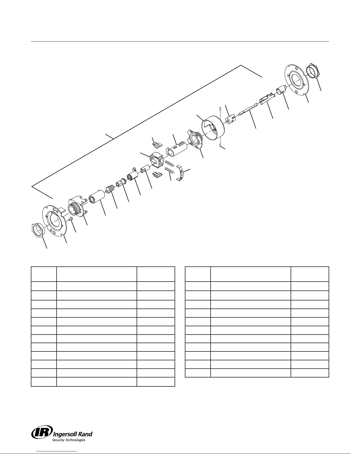
T511
Entry/Office Lock
2
35
14
12
36
24
1
8 (2)
6
23
7
34
11
13 (2)
21
10
19
9 (2)
18
17
16
15
5
4
3
2
Call Out
Number Description Part Number
1 Chassis Assembly, T511 A30756-000-00 14 Inner Mounting Plate 030712-000-30
2 Flanged Nut (2) 030726-000-30 15 Spindle, 1 Ear, Outer 030732-005-30
3 Outer Mounting Plate 030712-001-30 16 Clutch Spring 030709-000-60
4
#8-32 x 6” Self Tap Screw
5 Hub and Housing Assembly A30746-000-00 18 Key Spindle STD 030718-000-30
6 Spindle 030733-000-55 19 Push Actuator 030711-000-30
7 Retractor 022106-002-55 21 Slide Catch Spring 012107-001-60
8 Retractor Insert (2) 022986-001-50 23 Dogging Bar 030722-000-30
9 Retractor Spring (2) 022108-001-60 24 Push/Turn Button Mount 030731-000-30
10 Retractor Spring Retainer 022112-000-30 34 Short Slide Catch 022104-000-30
11 Hub and Plate Assembly A30747-000-00 35 Turn Button Sleeve 022133-000-50
12 Housing Case 022114-000-30 36 Turn Button Cap 030727-000*
13 Cotter Pin (2) 002893-000-60
031533-006-30 17 Clutch Driver 030716-001-30
Call Out
Number Description Part Number
T-Series Service Manual
13
Page 17
T511
Entry/Office Lock – IC
Chassis Assemblies
2
35
12
36
24
1
8 (2)
6
23
14
7
34
11
13 (2)
21
10
19
9 (2)
31
17
16
15
5
4
3
2
Call Out
Number Description Part Number
1 Chassis Assembly, T511-IC A30756-001-00 14 Inner Mounting Plate 030712-000-30
2 Flanged Nut (2) 030726-000-30 15 Spindle, 1 Ear, Outer 030732-005-30
3 Outer Mounting Plate 030712-001-30 16 Clutch Spring 030709-000-60
4
#8-32 x 6” Self Tap Screw
5 Hub and Housing Assembly A30746-000-00 19 Push Actuator 030711-000-30
6 Spindle 030733-000-55 21 Slide Catch Spring 012107-001-60
7 Retractor 022106-002-55 23 Dogging Bar 030722-000-30
8 Retractor Insert (2) 022986-001-50 24 Push/Turn Button Mount 030731-000-30
9 Retractor Spring (2) 022108-001-60 31 Key Spindle, IC 030718-001-30
10 Retractor Spring Retainer 022112-000-30 34 Short Slide Catch 022104-000-30
11 Hub and Plate Assembly A30747-000-00 35 Turn Button Sleeve 022133-000-50
12 Housing Case 022114-000-30 36 Turn Button Cap 030727-000*
13 Cotter Pin (2) 002893-000-60
031533-006-30 17 Clutch Driver 030716-001-30
Call Out
Number Description Part Number
14
T-Series Service Manual
Page 18
Chassis Assemblies
T521
Office Lock
1
8 (2)
2
35
14
12
36
24
6
23
7
13 (2)
11
10
9 (2)
19
18
17
16
15
5
4
3
2
Call Out
Number Description Part Number
1 Chassis Assembly, T521 A30748-000-00 13 Cotter Pin (2) 002893-000-60
2 Flanged Nut (2) 030726-000-30 14 Inner Mounting Plate 030712-000-30
3 Outer Mounting Plate 030712-001-30 15 Spindle, 1 Ear, Outer 030732-005-30
4
#8-32 x 6” Self Tap Screw
5 Hub and Housing Assembly A30746-000-00 17 Clutch Driver 030716-001-30
6 Spindle 030733-000-55 18 Key Spindle, STD 030718-000-30
7 Retractor 022106-002-55 19 Push Actuator 030711-000-30
8 Retractor Insert (2) 022986-001-50 23 Dogging Bar 030722-000-30
9 Retractor Spring (2) 022108-001-60 24 Push/Turn Button Mount 030731-000-30
10 Retractor Spring Retainer 022112-000-30 35 Turn Button Sleeve 022133-000-50
11 Hub and Plate Assembly A30747-000-00 36 Turn Button Cap 030727-000*
12 Housing Case 022114-000-30
031533-006-30 16 Clutch Spring 030709-000-60
Call Out
Number Description Part Number
T-Series Service Manual
15
Page 19
T521
Office Lock – IC
Chassis Assemblies
2
35
12
36
24
1
8 (2)
6
23
14
7
13 (2)
11
10
9 (2)
19
31
17
16
15
5
4
3
2
Call Out
Number Description Part Number
1 Chassis Assembly, T521-IC A30748-001-00 13 Cotter Pin (2) 002893-000-60
2 Flanged Nut (2) 030726-000-30 14 Inner Mounting Plate 030712-000-30
3 Outer Mounting Plate 030712-001-30 15 Spindle, 1 Ear, Outer 030732-005-30
4
#8-32 x 6” Self Tap Screw
5 Hub and Housing Assembly A30746-000-00 17 Clutch Driver 030716-001-30
6 Spindle 030733-000-55 19 Push Actuator 030711-000-30
7 Retractor 022106-002-55 23 Dogging Bar 030722-000-30
8 Retractor Insert (2) 022986-001-50 24 Push/Turn Button Mount 030731-000-30
9 Retractor Spring (2) 022108-001-60 31 Key Spindle, IC 030718-001-30
10 Retractor Spring Retainer 022112-000-30 35 Turn Button Sleeve 022133-000-50
11 Hub and Plate Assembly A30747-000-00 36 Turn Button Cap 030727-000*
12 Housing Case 022114-000-30
031533-006-30 16 Clutch Spring 030709-000-60
Call Out
Number Description Part Number
16
T-Series Service Manual
Page 20

Chassis Assemblies
T561
Classroom Lock
12
1
2
8 (2)
6
14
7
13 (2)
11
10
9 (2)
26
5
4
3
2
Call Out
Number Description Part Number
1 Chassis Assembly, T351/T561 A30758-000-00 9 Retractor Spring (2) 022108-001-60
2 Flanged Nut (2) 030726-000-30 10 Retractor Spring Retainer 022112-000-30
3 Outer Mounting Plate 030712-001-30 11 Hub and Plate Assembly A30747-000-00
4
#8-32 x 6” Self Tap Screw
5 Hub and Housing Assembly A30746-000-00 13 Cotter Pin (2) 002893-000-60
6 Spindle 030733-000-55 14 Inner Mounting Plate 030712-000-30
7 Retractor 022106-002-55 26 Key Spindle Assembly, STD A30780-000-30
8 Retractor Insert (2) 022986-001-50
031533-006-30 12 Housing Case 022114-000-30
Call Out
Number Description Part Number
T-Series Service Manual
17
Page 21

T561
Classroom Lock – IC
Chassis Assemblies
12
1
2
14
8 (2)
6
7
13 (2)
11
10
9 (2)
27
5
4
3
2
Call Out
Number Description Part Number
1 Chassis Assembly, T351/T561-ICA30758-001-00 9 Retractor Spring (2) 022108-001-60
2 Flanged Nut (2) 030726-000-30 10 Retractor Spring Retainer 022112-000-30
3 Outer Mounting Plate 030712-001-30 11 Hub and Plate Assembly A30747-000-00
4
#8-32 x 6” Self Tap Screw
5 Hub and Housing Assembly A30746-000-00 13 Cotter Pin (2) 002893-000-60
6 Spindle 030733-000-55 14 Inner Mounting Plate 030712-000-30
7 Retractor 022106-002-55 27 Key Spindle Assembly, IC A30780-001-30
8 Retractor Insert (2) 022986-001-50
031533-006-30 12 Housing Case 022114-000-30
Call Out
Number Description Part Number
18
T-Series Service Manual
Page 22

Chassis Assemblies
T571
Dormitory Lock
2
22
14
12
1
8 (2)
6
23
25
24
7
20
11
13 (2)
21
10
9 (2)
37
5
4
3
2
Call Out
Number Description Part Number
1 Chassis Assembly, T571 A30759-000-00 12 Housing Case 022114-000-30
2 Flanged Nut (2) 030726-000-30 13 Cotter Pin (2) 002893-000-60
3 Outer Mounting Plate 030712-001-30 14 Inner Mounting Plate 030712-000-30
4
#8-32 x 6” Self Tap Screw
5 Hub and Housing Assembly A30746-000-00 21 Slide Catch Spring 012107-001-60
6 Spindle 030733-000-55 22 Push Button Sleeve 022134-000-50
7 Retractor 022106-002-55 23 Dogging Bar 030722-000-30
8 Retractor Insert (2) 022986-001-50 24 Push/Turn Button Mount 030731-000-30
9 Retractor Spring (2) 022108-001-60 25 Push Button Cap 030728-000*
10 Retractor Spring Retainer 022112-000-30 37 Key Spindle Assembly, T571,
11 Hub and Plate Assembly A30747-000-00
031533-006-30 20 Slide Catch 022105-000-30
Call Out
Number Description Part Number
A30915-000-00
STD
*= Finish or Specify Finish on All
T-Series Service Manual
19
Page 23

T571
Dormitory Lock – IC
Chassis Assemblies
2
22
12
1
8 (2)
6
23
25
24
14
7
20
11
13 (2)
21
10
9 (2)
38
5
4
3
2
Call Out
Number Description Part Number
1 Chassis Assembly, T571-IC A30759-001-00 12 Housing Case 022114-000-30
2 Flanged Nut (2) 030726-000-30 13 Cotter Pin (2) 002893-000-60
3 Outer Mounting Plate 030712-001-30 14 Inner Mounting Plate 030712-000-30
4
#8-32 x 6” Self Tap Screw
5 Hub and Housing Assembly A30746-000-00 21 Slide Catch Spring 012107-001-60
6 Spindle 030733-000-55 22 Push Button Sleeve 022134-000-50
7 Retractor 022106-002-55 23 Dogging Bar 030722-000-30
8 Retractor Insert (2) 022986-001-50 24 Push/Turn Button Mount 030731-000-30
9 Retractor Spring (2) 022108-001-60 25 Push Button Cap 030728-000*
10 Retractor Spring Retainer 022112-000-30 38 Key Spindle Assembly, T571, IC A30915-001-00
11 Hub and Plate Assembly A30747-000-00
031533-006-30 20 Slide Catch 022105-000-30
Call Out
Number Description Part Number
20
T-Series Service Manual
Page 24

Chassis Assemblies
T581
Storeroom Lock
1
8 (2)
6
12
2
14
7
13 (2)
11
10
9 (2)
32
5
4
3
2
Call Out
Number Description Part Number
1 Chassis Assembly, T581 A30760-000-00 9 Retractor Spring (2) 022108-001-60
2 Flanged Nut (2) 030726-000-30 10 Retractor Spring Retainer 022112-000-30
3 Outer Mounting Plate 030712-001-30 11 Hub and Plate Assembly A30747-000-00
4
#8-32 x 6” Self Tap Screw
5 Hub and Housing Assembly A30746-000-00 13 Cotter Pin (2) 002893-000-60
6 Spindle 030733-000-55 14 Inner Mounting Plate 030712-000-30
7 Retractor 022106-002-55 32 Spindle, 2 Ear, STD 030732-000-30
8 Retractor Insert (2) 022986-001-50
031533-006-30 12 Housing Case 022114-000-30
Call Out
Number Description Part Number
T-Series Service Manual
21
Page 25

T581
Storeroom Lock – IC
Chassis Assemblies
1
8 (2)
6
12
2
14
7
13 (2)
11
10
9 (2)
33
5
4
3
2
Call Out
Number Description Part Number
1 Chassis Assembly, T581-IC A30760-001-00 9 Retractor Spring (2) 022108-001-60
2 Flanged Nut (2) 030726-000-30 10 Retractor Spring Retainer 022112-000-30
3 Outer Mounting Plate 030712-001-30 11 Hub and Plate Assembly A30747-000-00
4
#8-32 x 6” Self Tap Screw
5 Hub and Housing Assembly A30746-000-00 13 Cotter Pin (2) 002893-000-60
6 Spindle 030733-000-55 14 Inner Mounting Plate 030712-000-30
7 Retractor 022106-002-55 33 Spindle, 2 Ear, IC 030732-001-00
8 Retractor Insert (2) 022986-001-50
Call Out
Number Description Part Number
031533-006-30 12 Housing Case 022114-000-30
22
T-Series Service Manual
Page 26

Chassis Assemblies
T851
Storeroom Lock (Electrified – Fail Safe)
1
8 (2)
46
12
42
49
47
48
39
50
14
45
44
7
13 (2)
41
10
9 (2)
40
18
17
43
15
5
4
3
2
Call Out
Number Description Part Number
1 Chassis Assembly, T851 A31517-000-00 18 Key Spindle, STD 030718-000-30
2 Flanged Nut 030726-000-30 39 Solenoid, Fail Safe 031416-000-70
3 Outer Mounting Plate 030712-001-30 40 Push Acutator, Electrified Lock 030711-001-30
4
#8-32 x 6” Self Tap Screw
5 Hub and Housing Assembly A30746-000-00 42
7 Retractor 022106-002-55 43 Clutch Spring, Fail Safe 030709-001-30
8 Retractor Insert (2) 022986-001-50 44 Modified Cable Tie Q001-088-70
9 Retractor Spring (2) 022108-001-60 45
10 Retractor Spring Retainer 022112-000-30 46 Spindle, Inside, T851/T881 030733-002-55
12 Housing Case 022114-001-30 47
13 Cotter Pin (2) 002893-000-60 48 Solenoid Mounting 031514-000-30
14 Inner Mounting Plate 030712-000-30 49 Push Rod, Fail Safe 031513-001-60
15 Spindle, 1 Ear, Outer 030732-005-30 50 Flanged Nut, Inside, Electrified 030726-007-30
17 Clutch Driver 030716-001-30
031533-006-30 41 Hub and Plate Assembly,
Call Out
Number Description Part Number
A31538-001-00
Electrified
Special Nut, 56M” x 28
Fillister Head 4-40 x 56M Screw
Fillister Head 4-40 x 56 Screw
031511-000-30
031515-004-30
Q001-087
T-Series Service Manual
23
Page 27

T851
Storeroom Lock (Electrified – Fail Safe) – IC
1
8 (2)
46
12
42
Chassis Assemblies
39
47
48
49
45
44
50
14
7
13 (2)
41
10
9 (2)
40
31
17
43
15
5
4
3
2
Call Out
Number Description Part Number
1 Chassis Assembly, T851 A31517-000-00 18 Key Spindle, STD 030718-000-30
2 Flanged Nut 030726-000-30 39 Solenoid, Fail Safe 031416-000-70
3 Outer Mounting Plate 030712-001-30 40 Push Acutator, Electrified Lock 030711-001-30
4
#8-32 x 6” Self Tap Screw
5 Hub and Housing Assembly A30746-000-00 42
7 Retractor 022106-002-55 43 Clutch Spring, Fail Safe 030709-001-30
8 Retractor Insert (2) 022986-001-50 44 Modified Cable Tie Q001-088-70
9 Retractor Spring (2) 022108-001-60 45
10 Retractor Spring Retainer 022112-000-30 46 Spindle, Inside, T851/T881 030733-002-55
12 Housing Case 022114-001-30 47
13 Cotter Pin (2) 002893-000-60 48 Solenoid Mounting 031514-000-30
14 Inner Mounting Plate 030712-000-30 49 Push Rod, Fail Safe 031513-001-60
15 Spindle, 1 Ear, Outer 030732-005-30 50 Flanged Nut, Inside, Electrified 030726-007-30
17 Clutch Driver 030716-001-30
031533-006-30 41 Hub and Plate Assembly,
Call Out
Number Description Part Number
A31538-001-00
Electrified
Special Nut, 56M” x 28
Fillister Head 4-40 x 56M Screw
Fillister Head 4-40 x 56 Screw
031511-000-30
031515-004-30
Q001-087
24
T-Series Service Manual
Page 28

Chassis Assemblies
T881
Storeroom Lock (Electrified – Fail Secure)
1
8 (2)
46
12
42
53
47
48
52
50
14
45
44
7
13 (2)
41
10
9 (2)
40
18
17
51
15
5
4
3
2
Call Out
Number Description Part Number
1 Chassis Assembly, T851 A31517-000-00 18 Key Spindle, STD 030718-000-30
2 Flanged Nut 030726-000-30 39 Solenoid, Fail Safe 031416-000-70
3 Outer Mounting Plate 030712-001-30 40 Push Acutator, Electrified Lock 030711-001-30
4
#8-32 x 6” Self Tap Screw
5 Hub and Housing Assembly A30746-000-00 42
7 Retractor 022106-002-55 43 Clutch Spring, Fail Safe 030709-001-30
8 Retractor Insert (2) 022986-001-50 44 Modified Cable Tie Q001-088-70
9 Retractor Spring (2) 022108-001-60 45
10 Retractor Spring Retainer 022112-000-30 46 Spindle, Inside, T851/T881 030733-002-55
12 Housing Case 022114-001-30 47
13 Cotter Pin (2) 002893-000-60 48 Solenoid Mounting 031514-000-30
14 Inner Mounting Plate 030712-000-30 49 Push Rod, Fail Safe 031513-001-60
15 Spindle, 1 Ear, Outer 030732-005-30 50 Flanged Nut, Inside, Electrified 030726-007-30
17 Clutch Driver 030716-001-30
031533-006-30 41 Hub and Plate Assembly,
Call Out
Number Description Part Number
A31538-001-00
Electrified
Special Nut, 56M” x 28
Fillister Head 4-40 x 56M Screw
Fillister Head 4-40 x 56 Screw
031511-000-30
031515-004-30
Q001-087
T-Series Service Manual
25
Page 29

T881
Storeroom Lock (Electrified – Fail Secure) – IC
1
8 (2)
46
12
42
Chassis Assemblies
52
47
48
53
45
44
50
14
7
13 (2)
41
10
9 (2)
40
31
17
51
15
5
4
3
2
Call Out
Number Description Part Number
1 Chassis Assembly, T851 A31517-000-00 18 Key Spindle, STD 030718-000-30
2 Flanged Nut 030726-000-30 39 Solenoid, Fail Safe 031416-000-70
3 Outer Mounting Plate 030712-001-30 40 Push Acutator, Electrified Lock 030711-001-30
4
#8-32 x 6” Self Tap Screw
5 Hub and Housing Assembly A30746-000-00 42
7 Retractor 022106-002-55 43 Clutch Spring, Fail Safe 030709-001-30
8 Retractor Insert (2) 022986-001-50 44 Modified Cable Tie Q001-088-70
9 Retractor Spring (2) 022108-001-60 45
10 Retractor Spring Retainer 022112-000-30 46 Spindle, Inside, T851/T881 030733-002-55
12 Housing Case 022114-001-30 47
13 Cotter Pin (2) 002893-000-60 48 Solenoid Mounting 031514-000-30
14 Inner Mounting Plate 030712-000-30 49 Push Rod, Fail Safe 031513-001-60
15 Spindle, 1 Ear, Outer 030732-005-30 50 Flanged Nut, Inside, Electrified 030726-007-30
17 Clutch Driver 030716-001-30
031533-006-30 41 Hub and Plate Assembly,
Call Out
Number Description Part Number
A31538-001-00
Electrified
Special Nut, 56M” x 28
Fillister Head 4-40 x 56M Screw
Fillister Head 4-40 x 56 Screw
031511-000-30
031515-004-30
Q001-087
26
T-Series Service Manual
Page 30

Trim Assemblies
T101
Passage Latchset
P
NN
N
L
I
H
A
NN
K
J
O
H
E
F
Note: Spring Cage components require lubrication. See page 47 for specifications.
Call Out
Number Description Part Number
A Closed Lever, Outside See Page 46 K Mounting Post (2) 030715-000-30
E Lever Set Screw 030831-004-30 L Spring Latch A98535-000*
F Closed Lever and Set Screw
Assembly
H Rose 030706-002* O Spindle, Inside, Passage/Button 030703-000-30
I Spring Cage and Spindle,
Outside, Passage
J Spindle, Outside, Passage A30906-000-00 NN Non-Locking Spring Cage Q330-271
*= Finish or Specify Finish on All
T-Series Service Manual
Call Out
Number Description Part Number
A30753-00X* N
A30749-000-00 P Spring Cage and Spindle,
#8-32 x 6M” Combo Screw
Inside, Passage/Button
27
024416-012*
A30750-000-00
Page 31

T291
Privacy Hospital Lock
Trim Assemblies
P
NN
N
L
U
H
T
S
LL
B
NN
K
V
H
O
E
G
Note: Spring Cage components require lubrication. See page 47 for specifications.
Call Out
Number Description Part Number
B Open Lever, Outside See Page 46 P Spring Cage and Spindle, Inside,
E Lever Set Screw 030831-004-30 S Outer Button Mount 030729-000-70
G Open Lever and Set Screw
Assembly
H Rose 030706-002* U Spring Cage and Spindle,
K Mounting Post (2) 030715-000-30 V Spindle, Outside, Button A30905-000-00
L Spring Latch A98535-000* LL Button, T291, Outside Q033-044*
N
#8-32 x 6M” Combo Screw
O Spindle, Inside, Passage/Button 030703-000-30
*= Finish or Specify Finish on All
Call Out
Number Description Part Number
A30750-000-00
Passage/Button
A30753-01X* T Tailpiece, 6-pin IC 030739-000-30
A30796-000-00
Outside, Button
024416-012* NN Non-Locking Spring Cage Q330-271
28
T-Series Service Manual
Page 32

Trim Assemblies
T301
Privacy Lock
P
NN
N
L
U
H
T
S
Q
B
R
NN
K
V
H
O
E
G
Note: Spring Cage components require lubrication. See page 47 for specifications.
Call Out
Number Description Part Number
B Open Lever, Outside See Page 46 P Spring Cage and Spindle, Inside,
E Lever Set Screw 030831-004-30 Q Button Spacer 030787-000-70
G Open Lever and Set Screw
Assembly
H Rose 030706-002* S Outer Button Mount 030729-000-70
K Mounting Post (2) 030715-000-30 T Tailpiece, 6-pin IC 030739-000-30
L Spring Latch A98535-000* U Spring Cage and Spindle,
N
#8-32 x 6M” Combo Screw
O Spindle, Inside, Passage/Button 030703-000-30 NN Non-Locking Spring Cage Q330-271
*= Finish or Specify Finish on All
T-Series Service Manual
Call Out
Number Description Part Number
A30750-000-00
Passage/Button
A30753-01X* R Emergency Release Cap 030654-000*
A30796-000-00
Outside, Button
024416-012* V Spindle, Outside, Button A30905-000-00
29
Page 33

T351
Closet Lock
Trim Assemblies
W
NN
N
M
BB
H
AA
B
MM
K
CC
X
H
Y
E
Z
Note: Spring Cage components require lubrication. See page 47 for specifications.
Call Out
Number Description Part Number
B Open Lever, Outside See Page 46,47 Y Turn Knob, Knurled 030738-000*
E Lever Set Screw 030831-004-30 Z Turn Knob and Set Screw
H Rose 030706-002* AA 6-Pin Cylinder A23161-05*
K Mounting Post (2) 030715-000-30 BB Spring Cage and Spindle,
M Deadlatch A98535-00D* CC Spindle, Outside, 6-Pin Cylinder A30905-060-00
N
#8-32 x 6M” Combo Screw
W Spring Cage and Spindle, Inside,
T351
X Spindle, Inside, T351 030703-001-30
*= Finish or Specify Finish on All
Call Out
Number Description Part Number
A30788-000*
Assembly
A30910-060-00
Outside, 6-Pin Cylinder
024416-012* MM Locking Spring Cage Q330-270
A30776-001-00 NN Non-Locking Spring Cage Q330-271
30
T-Series Service Manual
Page 34

Trim Assemblies
T381
Classroom Security Lock
B
DD
NN
N
M
BB
H
AA
B
MM
K
CC
EE
H
AA
Note: Spring Cage components require lubrication. See page 47 for specifications.
Call Out
Number Description Part Number
B Open Lever, Outside See Page 46,47 BB Spring Cage and Spindle,
H Rose 030706-002* CC Spindle, Outside, 6-Pin Cylinder A30905-060-00
K Mounting Post (2) 030715-000-30 DD Spring Cage and Spindle, Inside,
M Deadlatch A98535-00D* EE Spindle, Inside, 6-Pin Cylinder A30906-060-00
N
#8-32 x 6M” Combo Screw
AA 6-Pin Cylinder A23161-05* NN Non-Locking Spring Cage Q330-271
*= Finish or Specify Finish on All
T-Series Service Manual
Call Out
Number Description Part Number
A30910-060-00
Outside, 6-Pin Cylinder
A30779-060-00
6-Pin Cylinder
024416-012* MM Locking Spring Cage Q330-270
31
Page 35

T411
Asylum Lock
Trim Assemblies
B
FF
MM
N
M
GG
H
AA
B
MM
K
CC
EE
H
AA
Note: Spring Cage components require lubrication. See page 47 for specifications.
Call Out
Number Description Part Number
B Open Lever, Outside See Page 46,47 CC Spindle, Outside, 6-Pin Cylinder A30905-060-00
H Rose 030706-002* FF Spring Cage and Spindle, Inside,
K Mounting Post (2) 030715-000-30 GG Spring Cage and Spindle,
M Deadlatch A98535-00D* EE Spindle, Inside, 6-Pin Cylinder 030906-060-00
N
#8-32 x 6M” Combo Screw
AA 6-Pin Cylinder A23161-05*
*= Finish or Specify Finish on All
Call Out
Number Description Part Number
A31523-060-00
6-Pin Cylinder, T411
A30749-060-00
Outside, 6-Pin Cylinder, T411/
T581
024416-012* MM Locking Spring Cage Q330-270
32
T-Series Service Manual
Page 36

Trim Assemblies
T501
Entry Lock
P
NN
N
M
BB
H
AA
B
MM
K
CC
O
H
E
G
Note: Spring Cage components require lubrication. See page 47 for specifications.
Call Out
Number Description Part Number
B Open Lever, Outside See Page 46,47 O Spindle, Inside, Passage/Button 030703-000-30
E Lever Set Screw 030831-004-30 P Spring Cage and Spindle, Inside,
G Open Lever and Set Screw
Assembly
H Rose 030706-002* BB Spring Cage and Spindle,
K Mounting Post (2) 030715-000-30 CC Spindle, 6-Pin Cylinder, Outside A30905-060-00
M Deadlatch A98535-00D* MM Locking Spring Cage Q330-270
N
#8-32 x 6M” Combo Screw
*= Finish or Specify Finish on All
T-Series Service Manual
Call Out
Number Description Part Number
A30750-000-00
Passage/Button
A30753-01X* AA 6-Pin Cylinder A23161-05*
A30910-060-00
Outside, 6-Pin Cylinder
024416-012* NN Non-Locking Spring Cage Q330-271
33
Page 37

T511
Entry/Office Lock
Trim Assemblies
P
NN
N
M
BB
H
AA
B
MM
K
CC
H
O
E
G
Note: Spring Cage components require lubrication. See page 47 for specifications.
Call Out
Number Description Part Number
B Open Lever, Outside See Page 46,47 O Spindle, Inside, Passage/Button 030703-000-30
E Lever Set Screw 030831-004-30 P Spring Cage and Spindle, Inside,
G Open Lever and Set Screw
Assembly
H Rose 030706-002* BB Spring Cage and Spindle,
K Mounting Post (2) 030715-000-30 CC Spindle, 6-Pin Cylinder, Outside A30905-060-00
M Deadlatch A98535-00D* MM Locking Spring Cage Q330-270
N
#8-32 x 6M” Combo Screw
*= Finish or Specify Finish on All
Call Out
Number Description Part Number
A30750-000-00
Passage/Button
A30753-01X* AA 6-Pin Cylinder A23161-05*
A30910-060-00
Outside, 6-Pin Cylinder
024416-012* NN Non-Locking Spring Cage Q330-271
34
T-Series Service Manual
Page 38

Trim Assemblies
T521
Office Lock
P
NN
N
M
BB
H
AA
B
MM
K
CC
H
O
E
G
Note: Spring Cage components require lubrication. See page 47 for specifications.
Call Out
Number Description Part Number
B Open Lever, Outside See Page 46,47 O Spindle, Inside, Passage/Button 030703-000-30
E Lever Set Screw 030831-004-30 P Spring Cage and Spindle, Inside,
G Open Lever and Set Screw
Assembly
H Rose 030706-002* BB Spring Cage and Spindle,
K Mounting Post (2) 030715-000-30 CC Spindle, 6-Pin Cylinder, Outside A30905-060-00
M Deadlatch A98535-00D* MM Locking Spring Cage Q330-270
N
#8-32 x 6M” Combo Screw
*= Finish or Specify Finish on All
T-Series Service Manual
Call Out
Number Description Part Number
A30750-000-00
Passage/Button
A30753-01X* AA 6-Pin Cylinder A23161-05*
A30910-060-00
Outside, 6-Pin Cylinder
024416-012* NN Non-Locking Spring Cage Q330-271
35
Page 39

T561
Classroom Lock
Trim Assemblies
P
NN
N
M
BB
H
AA
B
MM
K
CC
O
H
E
F
Note: Spring Cage components require lubrication. See page 47 for specifications.
Call Out
Number Description Part Number
B Open Lever, Outside See Page 46,47 O Spindle, Inside, Passage/Button 030703-000-30
E Lever Set Screw 030831-004-30 P Spring Cage and Spindle, Inside,
F Closed Lever and Set Screw
Assembly
H Rose 030706-002* BB Spring Cage and Spindle,
K Mounting Post (2) 030715-000-30 CC Spindle, 6-Pin Cylinder, Outside A30905-060-00
M Deadlatch A98535-00D* MM Locking Spring Cage Q330-270
N
#8-32 x 6M” Combo Screw
*= Finish or Specify Finish on All
Call Out
Number Description Part Number
A30750-000-00
Passage/Button
A30753-00X* AA 6-Pin Cylinder A23161-05*
A30910-060-00
Outside, 6-Pin Cylinder
024416-012* NN Non-Locking Spring Cage Q330-271
36
T-Series Service Manual
Page 40

Trim Assemblies
T571
Dormitory Lock
P
NN
N
M
BB
H
AA
B
MM
K
CC
O
H
E
G
Note: Spring Cage components require lubrication. See page 47 for specifications.
Call Out
Number Description Part Number
B Open Lever, Outside See Page 46,47 O Spindle, Inside, Passage/Button 030703-000-30
E Lever Set Screw 030831-004-30 P Spring Cage and Spindle, Inside,
G Open Lever and Set Screw
Assembly
H Rose 030706-002* BB Spring Cage and Spindle,
K Mounting Post (2) 030715-000-30 CC Spindle, 6-Pin Cylinder, Outside A30905-060-00
M Deadlatch A98535-00D* MM Locking Spring Cage Q330-270
N
#8-32 x 6M” Combo Screw
*= Finish or Specify Finish on All
T-Series Service Manual
Call Out
Number Description Part Number
A30750-000-00
Passage/Button
A30753-01X* AA 6-Pin Cylinder A23161-05*
A30910-060-00
Outside, 6-Pin Cylinder
024416-012* NN Non-Locking Spring Cage Q330-271
37
Page 41

T581
Storeroom Lock
Trim Assemblies
P
NN
N
M
GG
H
AA
B
MM
K
CC
O
H
E
F
Note: Spring Cage components require lubrication. See page 47 for specifications.
Call Out
Number Description Part Number
B Open Lever, Outside See Page 46,47 O Spindle, Inside, Passage/Button 030703-000-30
E Lever Set Screw 030831-004-30 P Spring Cage and Spindle, Inside,
F Closed Lever and Set Screw
Assembly
H Rose 030706-002* CC Spindle, 6-Pin Cylinder, Outside A30906-060-00
K Mounting Post (2) 030715-000-30 GG Spring Cage, Outside, T411/
M Deadlatch A98535-00D* MM Locking Spring Cage Q330-270
N
#8-32 x 6M” Combo Screw
*= Finish or Specify Finish on All
Call Out
Number Description Part Number
A30750-000-00
Passage/Button
A30753-00X* AA 6-Pin Cylinder A23161-05*
A30749-060-00
F581
024416-012* NN Non-Locking Spring Cage Q330-271
38
T-Series Service Manual
Page 42

Trim Assemblies
T851
Storeroom Lock (Electrified – Fail Safe)
JJ
NN
N
M
BB
H
AA
B
MM
K
CC
KK
H
E
HH
Note: Spring Cage components require lubrication. See page 47 for specifications.
Call Out
Number Description Part Number
B Open Lever, Outside See Page 46,47 BB Spring Cage and Spindle,
E Lever Set Screw 030831-004-30 CC Spindle, Outside, 6-Pin Cylinder A30905-060-00
H Rose 030706-002* HH T851/T881 Lever and Set Screw
K Mounting Post (2) 030715-000-30 JJ Spring Cage and Spindle, Inside,
M Deadlatch A98535-00D* KK Spindle, Inside, T851/T881 031519-000-30
N
#8-32 x 6M” Combo Screw
AA 6-Pin Cylinder A23161-05* NN Non-Locking Spring Cage Q300-271
*= Finish or Specify Finish on All
T-Series Service Manual
Call Out
Number Description Part Number
A30910-060-00
Outside, 6-Pin Cylinder
A31544-00X*
Assembly
A31638-000-00
T851/T881
024416-012* MM Locking Spring Cage Q330-270
39
Page 43

T881
Storeroom Lock (Electrified – Fail Secure)
Trim Assemblies
JJ
NN
N
M
BB
H
AA
B
MM
K
CC
KK
H
E
HH
Note: Spring Cage components require lubrication. See page 47 for specifications.
Call Out
Number Description Part Number
B Open Lever, Outside See Page 46,47 BB Spring Cage and Spindle,
E Lever Set Screw 030831-004-30 CC Spindle, Outside, 6-Pin Cylinder A30905-060-00
H Rose 030706-002* HH T851/T881 Lever and Set Screw
K Mounting Post (2) 030715-000-30 JJ Spring Cage and Spindle, Inside,
M Deadlatch A98535-00D* KK Spindle, Inside, T851/T881 031519-000-30
N
#8-32 x 6M” Combo Screw
AA 6-Pin Cylinder A23161-05* NN Non-Locking Spring Cage Q300-271
*= Finish or Specify Finish on All
Call Out
Number Description Part Number
A30910-060-00
Outside, 6-Pin Cylinder
A31544-00X
Assembly
A31638-000-00
T851/T881
024416-012* MM Locking Spring Cage Q330-270
40
T-Series Service Manual
Page 44

Cylinders
Standard Cylinders
Falcon Complete Standard Cylinders
Function 5-Pin Cylinder 6-Pin Cylinder 7-Pin Cylinder
A23151-05 A23161-05 A23171-05
All Except T381IS, T571
A23151-06 A23161-06 A23171-06
T381IS
A23151-07 A23161-07 A23171-07
T571
Notes: 1) Finishes 606 and 626 only
2) Specify Keyway
3) Cylinders are funished G keyway, keyed differently unless otherwise specified.
4) Restricted sections require additional fee.
Standard Cylinder Options
Description Specify
5 Pinned Cylinder
6 Pinned Cylinder
7 Pinned Cylinder
Competitor Keyway Cylinders (6 Pin Only)*
*Cylinders are furnished 0-bitted unless otherwise specified. No master keying, except Schlage C.
P suffix
Example: T581PD DAN
P6 suffix
Example: T581PD6 DAN
P7 suffic
Example: T581PD7 DAN
P6 suffix
Example: T581PD6 SCH C
Standard Cylinder Tailpieces
Cylinders Std. Functions T381 Inside T571
Falcon 6-pin* (10 pack) A30730-001-00 A30730-003-00 A30730-002-00
Falcon 7-pin (10 pack) A30730-002-00 A30730-004-00 A30730-006-00
Sargent 6 & 10 Line 030997-001-30 030997-003-30 030997-005-30
Yale 1801, 5801 030917-001-30 030917-003-30 030917-005-30
*Assa 65611 and 65661, Corbin Russwin 2000-034 and Schlage (including Primus) all use Falcon 6-pin tailpiece.
T-Series Service Manual
41
Page 45

Cylinders
Competitor Keyway Compatibility
Falcon T-Series locks are furnished with Falcon’s standard “G” keyway cylinder unless otherwise specified. The
following cylinders manufactured by competitors are acceptable.
Assa (65611 or 65661) 6-pins
Sargent (6,7 and 10 Line) 6-pin s
- Keso not available
Peaks (Kaba) 6-pins
Medeco (20W200V3) 6-pins
-Tailpiece supplied by Medeco
-Falcon/Schlage style
Schlage Standard 6-pins
Schlage Primus 6-pins
Yale (1801) 6-pin s
- Bicentric not available
Corbin Russwin (2000-034/CL3400) 6-pin s
- Master Ring not available
IC Cylinders
Falcon Complete IC Cylinders
Style Combinated 6-Pin Combinated 7-Pin Uncombinated 6-Pin Uncombinated 7-Pin
C606 C607 C646 C647
Standard
Standard with Best-Style Capping
No Logo
No Logo with Best-Style Capping
Notes: 1) Specify core number, keyway and finish when ordering.
CB806 CB807 CB846 CB847
C608 C609 C648 C649
CB808 CB809 CB848 CB849
42
T-Series Service Manual
Page 46

Cylinders
IC Cylinder Options
Description Specify
Small Format Core*
Small Format Construction Core**
Less Small Format Core
Less Full Size Core
Small Format Disposable Core
*Locks are furnished uncombinated with no keys unless otherwise specified.
**Locks are assessed one non-refundable handling charge per core.
IC Cylinder Tailpieces
Cylinders Std. Functions T381 Inside T571
Falcon 6-pin* 030739-000-30 030739-002-30 030739-000-30
Falcon 7-pin* 030739-001-30 030739-003-30 030739-001-30
Corbin Russwin 8000 and Sargent 6300 031468-000-30 031468-002-30 031468-004-30
Corbin Russin 8000-7 (7-Pin) 031468-001-00 031468-003-30 031468-005-30
Medeco 32 Series and ASSA A30988-000-00 A30988-002-00 A30988-004-00
Schlage Full Size (Including Primus) 031467-000-30 031467-002-30 031467-004-30
Yale and Medeco 31 Series, 6-Pin 030917-001-30 030917-003-30 030917-005-30
*Arrow, Best, InstaKey, Kaba Peaks, Keymark, KSP and Schlage small format cores all use the Falcon configuration.
G suffix
Example: T581GD6 DAN
H suffix
Example: T581HD7 DAN
B suffix
Example: T581BD DAN
J suffix
Example: T581JD SCH DAN
BDC suffix
Example: T581BDC DAN
Competitor IC Compatibility
Locksets with the standard Falcon interchangeable core option can also accept Schlage SFIC, Arrow (including Flex
Core), Best (including PKS and Peaks), InstaKey, Kaba Peaks, Keymark and KSP cores.
In addition, the following larger format interchangeable cores will work when lockset is so specified.
Assa
Old & new style
Specify IC-AS
T-Series Service Manual
Corbin
Russwin
Corbin Russwin
8000 or 8000-7
Specify IC-CR6
or IC-CR7
32 Series 6-Pin
Specify IC-ME
Medeco
32
Medeco
Medeco
31
Medeco
31 Series 6-Pin
Specify IC-YA6
43
Sargent
6300
Sargent
6300
Specify IC-SA
Schlage Yale
Schlage 6-Pin
including Primus
Specify IC-SC
Yale 6-Pin
Specify IC-YA6
Page 47

Inside Inserts and Spindles
Inserts and Spindles
Description Part Number
Insert and Spindle A30750-000-00 ssssss
Insert and Spindle A30776-001-00 s
Falcon 6-Pin and 7-Pin IC A30779-001-00 s
Falcon and Mono 6-Pin Standard A30779-060-00 s
Falcon 7-Pin Standard A30779-070-00 s
Medeco IC A30981-001-00 s
Schlage IC A30982-001-00 s
Corbin-Russwin 6-Pin IC A30983-001-00 s
Corbin-Russwin 7-Pin IC A30983-002-00 s
Yale IC A30984-001-00 s
Sargent IC A30985-001-00 s
Sargent 6-Pin Standard A31491-060-00 s
Yale 6-Pin Standard A31492-060-00 s
Yale 7-Pin Standard A31492-070-00 s
Falcon 6-Pin and 7-Pin IC A31523-001-00 s
Falcon and Mono 6-Pin Standard A31523-060-00 s
Falcon 7-Pin Standard A31523-070-00 s
Medeco IC A31524-001-00 s
Schlage IC A31525-001-00 s
Corbin-Russwin 6-Pin IC A31526-001-00 s
Corbin-Russwin 7-Pin IC A31526-002-00 s
Yale IC A31527-001-00 s
Sargent IC A31528-001-00 s
Sargent 6-Pin Standard A31529-060-00 s
Insert and Spindle A31638-000-00 ss
ASSA IC A31643-001-00 s
ASSA IC A31644-001-00 s
T351 T381 T411 T501 T511 T521 T561 T571 T581 T851 T881
44
T-Series Service Manual
Page 48

Inserts and Spindles
Outside Inserts and Spindles
Description Part Number
Falcon 6-Pin and 7-Pin IC A30749-001-00 ss
Falcon and Mono 6-Pin Standard A30749-060-00 ss
Falcon 7-Pin Standard A30749-070-00 ss
Falcon IC A30910-001-00 ss sssss ss
Falcon and Mono 6-Pin Standard A30910-060-00 ss sssss ss
Falcon 7-Pin Standard A30910-070-00 ss sssss ss
Medeco IC A30941-001-00 ss sssss ss
Schlage IC A30942-001-00 ss sssss ss
Corbin-Russwin 6-Pin IC A30943-001-00 ss sssss ss
Corbin-Russwin 7-Pin IC A30943-002-00 ss sssss ss
Yale IC A30944-001-00 ss sssss ss
Sargent IC A30945-001-00 ss sssss ss
Medeco IC A30971-001-00 ss
Schlage IC A30972-001-00 ss
Corbin-Russwin IC A30973-001-00 ss
Corbin-Russwin 7-Pin IC A30973-002-00 ss
Yale IC A30974-001-00 ss
Sargent IC A30975-001-00 ss
Sargent 6-Pin Standard A31485-060-00 s sssss ss
Yale 6-Pin Standard A31486-060-00 ss sssss ss
Yale 7-Pin Standard A31486-070-00 ss sssss ss
Sargent 6-Pin Standard A31487-060-00 ss
Yale 6-Pin Standard A31488-060-00 s
Yale 7-Pin Standard A31488-070-00 s
ASSA IC A31641-001-00 ss
ASSA IC A31642-001-00 ss sssss ss
T351 T381 T411 T501 T511 T521 T561 T571 T581 T851 T881
T-Series Service Manual
45
Page 49

Closed Levers
Style Part Number Description
030740-000-xxx Standard Closed Lever
A30753-00A-xxx Inside Lever with Set Screw
Levers
Avalon
Dane
Quantum
Notes: 1) Specify finish on end of part number (ex. 030740-000-626)
A31544-00A-xxx Inside Lever with Set Screw for T851/T881 Functions
030742-000-xxx Standard Closed Lever
A30753-00D-xxx Inside Lever with Set Screw
A31544-00D-xxx Inside Lever with Set Screw for T851/T881 Functions
030744-000-xxx Standard Closed Lever
A30753-00Q-xxx Inside Lever with Set Screw
A31544-00Q-xxx Inside Lever with Set Screw for T851/T881 Functions
Open Levers
Style Part Number Description
030740-001-xxx Standard Open Lever
030929-001-xxx Corbin Russwin, Medeco, Yale unit Open Lever
030996-001-xxx Sargent 6, 7 and 10 Line, Yale Open Lever
Avalon
Dane
Quantum
Notes: 1) Specify finish on end of part number (ex. 030740-000-626)
A30753-01A-xxx Inside Lever with Set Screw
030742-001-xxx Standard Open Lever
030929-002-xxx Corbin Russwin, Medeco, Yale unit Open Lever
030996-002-xxx Sargent 6, 7 and 10 Line, Yale Open Lever
A30753-01D-xxx Inside Lever with Set Screw
030744-001-xxx Standard Open Lever
030929-003-xxx Corbin Russwin, Medeco, Yale unit Open Lever
030996-003-xxx Sargent 6, 7 and 10 Line, Yale Open Lever
A30753-01Q-xxx Inside Lever with Set Screw
46
T-Series Service Manual
Page 50

Levers
SFIC/IC Levers
Style Part Number Description
030740-002-xxx Standard SFIC Lever
030926-001-xxx Assa, Medeco, Yale IC Lever
030927-001-xxx Schlage IC Lever
Avalon
Dane
Quantum
Notes: 1) Specify finish on end of part number (ex. 030740-000-626)
030928-001-xxx Corbin Russwin IC Lever
030930-001-xxx Sargent IC Lever
030742-002-xxx Standard SFIC Lever
030926-002-xxx Assa, Medeco, Yale IC Lever
030927-002-xxx Schlage IC Lever
030928-002-xxx Corbin Russwin IC Lever
030930-002-xxx Sargent IC Lever
030744-002-xxx Standard SFIC Lever
030926-003-xxx Assa, Medeco, Yale IC Lever
030927-003-xxx Schlage IC Lever
030928-003-xxx Corbin Russwin IC Lever
030930-003-xxx Sargent IC Lever
Spring Cage Replacement Kits
Q330-270 - Locking Spring Cage Q330-271 - Non-Locking Spring Cage
Apply light film of M204-250 on surfaces with brush or equivalent.
Barrel or tumble with M204-250 to acheive approximately .015-.040 film thickness
T-Series Service Manual
47
Page 51

Grade 1 Latches
Latches and Accessories
A98535-000
Square Corner Spring Latch,
6QE” Projection
A98538-00D
6QE” Radius Corner Deadlatch,
6QE” Projection
Grade 2 Latches
A98535-00D
Square Corner Deadlatch,
6QE” Projection
A98835-00D
Square Corner Deadlatch,
6M” Projection
A98538-000
6QE” Radius Corner Spring Latch,
6QE” Projection
A98838-000
6QE” Radius Corner Spring Latch,
6M” Projection
A92320-000
Square Corner Spring Latch,
56O” Projection, 26” Backset
A92320-00D
Square Corner Deadlatch,
56O” Projection, 26” Backset
48
A92321-000
56M” Radius Cor ner Spr ing Latch,
56O” Projection, 26” Backset
T-Series Service Manual
Page 52

Latches and Accessories
A92321-00D
56M” Radius Cor ner Deadlatch,
56O” Projection, 26” Backset
A92331-000
56M” Radius Corner Spr ing Latch,
56O” Projection, 26M” Backset
Accessories
A92330-000
Square Corner Spr ing Latch,
56O” Projection, 26M” Backset
A92331-00D
56M” Radius Cor ner Deadlatch,
56O” Projection, 26M” Backset
A92330-00D
Square Corner Deadlatch,
56O” Projection, 26M” Backset
A22161-005-00
Link for 5" Backset
For use with 26M” backset latches
(except 6M” projection)
T-Series Service Manual
A30775-000-00
Thin Door Installation Kit
For door thicknesses 16”–16M”
49
Page 53

Strikes
Strike and Dust Boxes
Full Lip Square Corner Strike
Dust Boxes
005164-000
ANSI Strike
Q001-049
A05185-000
Square Corner T-Strike
Q001-048
Full Lip 56M” Radius Corner Strike
A05185-004
6QE” Radius Corner T-Strike,
K510-066-PLA 012191-003-70 Q001-059
50
T-Series Service Manual
Page 54

Preparation and Installation
Installation Template
For reference only. DO NOT place on door for drilling.
FOLD HERE &
PLACE ON HIGH
EDGE OF DOOR BEVEL
Mark Centerline of Latch for
Correct Door Thickness.
Drill 1"(25mm) diameter hole.
17N"(45mm)
2"(51mm)
267N"(57mm)
Tailpiece Installation
T–Series
Lever Lock
Template
Mark Center for
Latch
High Edge
267"(54mm) Hole
27N"(70mm) BACKSET
IMPORTANT:
Check lock for proper backset
BEFORE drilling
Mark Center for
7RF"(8mm) Holes
Use of Drill Fixture
030736-000-50
recommended to
ensure proper
alignment of
thru-bolt holes.
7;P"(4mm)
7;P"(4mm) x 67"(3mm) deep
(800) 266-4456
©
2008 Schlage Lock Company
Printed in Country
030793-000-70 Rev. 04/08-b
Door Centering Adjustment
267N"(57mm) Door
17N"(44mm) Door
2"(51mm) Door
T-Series Tailpiece Installation
For proper function of the lock, the right tailpiece must be used and installed correctly.
All T-locks with standard cylinders must have the tailpiece installed
VERTICALLY on the cylinder as shown.
NOTE: The cap must be properly adjusted.
If too loose, excessive plug end play will prevent the key from being withdrawn.
If too tight, the plug will drag and be difficult to rotate with the key.
Cylinder
Spring
Pin
Tailpiece
800-266-4456
©
2008 Schlage Lock Company
Printed in Country
030102-000-70 Rev. 04/08-b
Cap
T-Series Service Manual
51
Page 55

03079400070
INSTALLATION INSTRUCTIONS FOR INSTALLING
T-SERIES
EXTRA HEAVY DUTY LEVER LOCKSET
IMPORTANT: THIS LOCK IS NON-HANDED. LOCK IS FACTORY PACKED PREADJUSTED FOR 17N" (45mm)
THICK DOORS. TO ADJUST LOCK FOR OTHER DOOR THICKNESS, SEE STEP 8, 9 & 10. SPACERS MUST
BE USED FOR DOORS THINNER THAN 17N" (45mm) THICK. FOR FUNCTIONS
SEE STEPS 17 (STANDARD CYLINDER) OR 18 (IC CORE) FOR TIMING INSTRUCTIONS.
& T571
Set Screw
67N-20 x 67N"
Mounting Screws
#10-32 x 1"
Outer Trim Assembly
Interchangeable Core Cylinder
Flange Nut
Inner Mounting Plate
*Spacer
Spacer required for all
doors under 17N" thick.
Attaching Screws
#8 Combination
Latch Assembly
INSIDE
Chassis Assembly
Outer Trim Assembly
Standard Cylinder
*Spacer
Spacer required for all
door under 17N" thick.
OUTSIDE
T341, T351, T371, T381, T391, T561
Inner Lever
Rose
Inner Trim Assembly
INSIDE
RIGHT HAND
LEFT HAND
LEFT HAND REVERSE
RIGHT HAND REVERSE
OUTSIDE
LEFT HAND REVERSE SHOWN
STEP 1
MARK DOOR
Fold template on line indicated.
Place on HIGH EDGE of door bevel.
Position centerline of template on heightline (suggested
height is 38" (965mm) from floor).
A. Locate and mark center for 267" (54mm) hole.
B. Locate and mark positions for notches.
Caution: Notches must be horizontal.
C. Locate and mark center for two (2)7RF" (8mm)
thru-bolt holes.
D. Locate and mark center for 1" (25mm) latch bolt hole
in door edge.
Note: If steel frames are used, the latch centerline must
be in line with the center of the strike preparation.
Hint: For retrofitting of existing 267" (54mm) holes, fold template in half to locate position for the two (2) 7RF" (8mm) holes.
"(45mm) DR
/
4
3
2"(51mm) DR
1
B) Mark Notches
A) Mark 267" Hole
C) Mark Thru-Bolt Holes
52
"(57mm) DR
/
4
1
2
DOOR CENTERING ADJUSTMENT
x1/8"(3mm) DEEP
5/32"(4mm)
5/32"(4mm)
HOLES.
THRU-BOLT
ALIGNMENT OF
ENSURE PROPER
High Edge Of Bevel Door
RECOMMENDED TO
030736-000-50 IS
USING DRILL FIXTURE
5/16"(8mm) HOLES
MARK CENTER FOR
2 1/8"(54mm) HOLE
MARK CENTER FOR
DOOR HANDS DETERMINED FROM OUTSIDE
2 1/4"(57mm)
BACKSET BEFORE DRILLING
CHECK LOCK FOR PROPER
2"(51mm)
IMPORTANT:
(45mm)
1 3/4"
2 3/4"(70mm) BACKSET
HIGH EDGE
LATCH
LOCKS
T–SERIES LEVER
INSTALLING
D) Mark Latch Hole
DRILL 1"(25mm) DIA HOLE.
FOR CORRECT DOOR THICKNESS.
MARK CENTERLINE OF LATCH
EDGE OF DOOR
PLACE ON HIGH
FOLD HERE &
TEMPLATE FOR
T-Series Service Manual
Page 56

STEP 2
BORE HOLES: INSTALL LATCH
When drilling through door, be careful not to damage door finish.
A) 5/16" (8mm)
Thru hole
A. Bore a 267" (54mm) hole and two (2) 7RF" (8mm) holes
from both sides of door to avoid splintering wood.
C) File Notches
B. Bore a 1" (25mm) hole into door edge. Using latch faceplate
as pattern, trace outline and mortise door edge so latch is flush
with door. If 7N projection latch is to be installed see Step 20.
Note: For wood jambs, close door and using a strike-locating tool
A) 2-1/8" (54mm)
Thru hole
A) 5/16" (8mm)
Thru hole
or other pointed object mark position of hole in jamb. Open door
and drill 1" (25mm) hole in jamb minimum 7N" (19mm) deep.
C. File two (2) 7;P" (4mm) x 7;P" (4mm) x 67" (3mm) deep notches
into both sides of door.
D. Insert latch unit in door, making certain that latch bolt bevel faces
direction of closing door. Attach with two #8 combination screws
provided.
Note: Use of a drill guide is recommended to ensure
straight and level holes.
IF USING THE FALCON OPTIONAL DRILL GUIDE
Install Drill Guide (030736-000-70) into door. Make certain correct backset
locators are even with door edge. Drill two (2) 7RF" (8mm) holes from both
sides to center.
B) 1" (25mm) Hole
Latch Unit
Use faceplate as pattern for mortise.
Backset
Locator
5/32"
Latch
Bolt Bevel
Note: Drill guide replacement is recommended after 10 door preparations.
STEP 3
INSTALL CHASSIS AND OUTER TRIM ASSEMBLY
Note: For ease of installation, lock should be in
the unlocked position.
Slide chassis assembly into door from outside
making sure that lock housing engages latch
prongs. Retractor must also engage latch tail.
Important: Chassis assembly must be positioned
in center of door for proper operation.
STEP 4
INSTALL INNER MOUNTING PLATE
A. Place inner mounting plate onto chassis assembly
making sure that plate tabs engage horizontal
notches in door.
B. Position flanged nut over chassis assembly and
tighten securely with hex wrench provided.
Lock Housing
Chassis Assembly
Latch Prong
Latch Tail
Retractor
Latch Case
Outside of Door
Notches
Tab
Flanged Nut
Black Hex Wrench Chassis Assembly
Tab
T-Series Service Manual
Inner Mounting Plate
53
Page 57

STEP 5
INSTALL INNER TRIM ASSEMBLY
Thru Post
Slide inner trim assembly over chassis spindle. Thru-posts will
engage inner trim asembly on 17N" (45mm) thick doors.
Secure to door with two #10-32 x 1" machine screws provided.
STEP 6
INSTALL INNER LEVER
A. Position rose over inner trim assembly making sure rose
detent engages groove in spindle assembly.
B. Install lever handle and tighten set screw with hex key
provided.
Stop! Test operation to be sure latch bolt moves freely. Do not force.
If lockset does not operate properly, remove lockset from door and
check door preparation and door thickness adjustment. See Step 4
to re-install chassis.
Thru Post
Chassis Spindle
Inner Trim Assembly
Groove
Rose
Inner Trim Asssembly
Rose Detent
67N-20 x 67N"
Set Screw
Mounting Screws
#10-32 x 1"
Inner Lever
STEP 7
LOCATE AND INSTALL STRIKE
A. For wood jambs center strike latch opening over 1" (25mm)
hole in jamb. Trace outline around the strike on door jamb.
B. Mortise door jamb to accommodate strike box and strike.
C. Insert strike box if required and fasten strike to jamb with
combination screws provided.
Caution: Deadlocking plunger of latch bolt must not enter
opening in strike plate.
Note: When strike box is not used, recess in jamb must be
a minimum of 7RF" (14mm) deep to allow latch bolt to extend
to its full projection.
STEP 8
INSTRUCTIONS FOR REMOVING OUTSIDE TRIM
A. Remove the outside trim retaining screw (A).
B. Slide the outside trim (B) from the chassis assembly.
C. See Step 9 for chassis adjustment procedure,
or Step 10 for spacer installation.
Mortise for
dust box
and strike
Mortise for
dust box
and strike
Jamb
ANSI Dust Box
ANSI Strike
#12 Combination Screw
Jamb
Dust Box
T-Strike
#8 Combination
Screw
B
A
D. Slide the outside trim (B) onto the chassis.
E. Replace the outside trim retaining screw (A).
54
T-Series Service Manual
Page 58

STEP 9
ADJUST LOCK FOR DOOR THICKNESS
Lock is factory packed preadjusted for 17N" (45mm) doors unless
ordered special.
A. Place template provided against retractor housing to find
marking for door thickness.
1 3/4"(45mm) DR
2"(51mm) DR
5/32"(4mm)
5/32"(4mm)
2 1/4"(57mm) DR
DOOR CENTERING ADJUSTMENT
x1/8"(3mm) DEEP
ALIGNMENT
PROPER
ENSURE
MENDED TO
RECOM-
030736-000-50 IS
FIXTURE
USING DRILL
5/16"(8mm) HOLES
MARK CENTER FOR
2 1/8"(54mm) HOLE
MARK CENTER FOR
BACKSET BEFORE DRILLING
CHECK LOCK FOR PROPER
IMPORTANT:
(45mm)
1 3/4"
2 3/4"(70mm) BACKSET
HIGH EDGE
LATCH
LOCKS
T–SERIES LEVER
INSTALLING
TEMPLATE FOR
2 1/4"(57mm)
2"(51mm)
THICKNESS.
FOR CORRECT DOOR
MARK CENTERLINE OF LATCH
PLACE ON HIGH
FOLD HERE &
B. If adjustment is necessary, use hex wrench provided
and rotate flanged nut counterclockwise to adjust.
Again, use template markings to measure adjustment
before installing lock on door.
Hint: Three full turns of nut equals (=) 67" (3mm) adjustment.
C. Pinch button mount legs together and
move cap to desired position.
STEP 10
INSTALLING SPACER FOR DOORS THINNER
THAN 17N" (45mm)
A. Remove flanged nut with blakc hex wrench
pro-vided along with outer mounting plate.
B. Place on spacer over outer chassis spindle
as shown.
C. Re-install outer mounting plate and flanged nut.
Using adjusting gage provided adjust flanged nut
for proper door thickness as shown.
D. See Step 4 for chassis installation.
E. Place second spacer over inner chassis spindle
before installing inner mounting plate and
flanged nut. Continue at Step 5.
Flanged Nut
Chassis Assembly
DOOR CENTERING
ADJUSTMENT GAGE
NT FALCON T-SERIES LEVER
LOCKS FOR DOORS LESS THAN
1 3/4 (45mm) THICK
1 3/4 (45mm)
1 1/4 (32mm)
1 1/2 (38mm)
Outer Mounting Plate
NT FALCON LOCK
P/N 030793-001-70
PRINTED IN U.S.A.
Spacer
Outer Mounting Plate
Flanged Nut
Black Hex Wrench
Gage
Chassis Assembly
Spacer
Button Mount Legs
Inner Mounting Plate
Inside
Outside
267N"
(57mm)
2"
(51mm)
Flanged Nut
Spacer
Cap
17N"
(45mm)
STEP 11
TO REMOVE ALL LEVERS WITH INTERCHANGEABLE CORE CYLINDERS
A. Insert control key into core and rotate 15 degrees clockwise.
Pull key to remove core.
B. Insert screwdriver into Figure "8" core hole and into lever
retainer.
C. Depress retainer and slide lever off spindle.
TO RE-INSTALL LEVER
D. Slide lever over spindle and push on over retainer.
E. Pull on lever to be sure retainer engaged lever.
F. Re-install core with tailpiece pushed into core.
STEP 12
Be certain to use correct tailpiece with core.
IC CORE AND TAILPIECE
6 Pin Core
FALCON
Six pin cores should only use the "6P" tailpiece.
Seven pin cores should only use the "7P" tailpiece.
FALCON
Push
Retainer
Control Key
7 Pin Core
T-Series Service Manual
55
Page 59

STEP 13
TO REMOVE ALL CYLINDER LEVERS
(Except Interchangeable Core)
A. Insert key and rotate clockwise approximately 60 degrees.
B. Depress lever retainer with tool provided.
C. Slide lever off spindle.
TO RE-INSTALL LEVER
D. Insert cylinder into spindle.
E. Slide lever onto spindle.
F. Insert key into cylinder and rotate clockwise approximately
60 degrees and push lever over retainer.
C
B
G. Pull on lever to be sure retainer engaged lever.
STEP 14
TAILPIECE INSTALLATION
For proper function of the lock the tailpiece must be installed correctly.
All T-Series tailpieces should be installed VERTICALLY in the cylinder.
STEP 15
DOUBLE DUMMY TRIM, T18
A. Using template described in Step 1,
locate and mark center for two (2)
7RF" (8mm) Thru-Bolt Holes.
Outer Trim Assembly
B. Bore two (2) 7RF" (8 mm) holes
from both sides of door to avoid
splintering wood.
C. Holding outer trim against door,
position inner spindle assembly over
thru-posts and secure to door with two
#10-32 x 1" machine screws provided.
Outside of Door
D. See Step 6 for lever installation.
A
Cylinder
7RF" (8mm) Holes
Spring
Pin
Tailpiece
Mounting Screws
#10-32 x 1"
Cap
Thru Post
Inside of Door
Inner Trim
Assembly
Groove
STEP 16
SINGLE DUMMY TRIM, T12
A. Using template described in Step 1, locate and mark
center for two (2) mounting holes.
B. For Wood Door - Drill two (2) pilot holes
7;P" (4mm) x )7" (22mm) deep for #12 wood screws.
For Metal Door - Drill and tap two (2) holes
for #12-24 machine screws.
C. Position spindle assembly over mounting holes and
secure to door with screws provided.
D. See Step 6 for lever installation.
56
Inside of Door
Inner Trim Assembly
Groove
Screws for Metal Doors
#12-24 x 7N"
Screws for Wood Doors
#12 x 167P"
T-Series Service Manual
Page 60

STEP 17
TIMING INSTRUCTIONS FOR STANDARD CYLINDER LOCKS
FOR THE FOLLOWING FUNCTIONS: T341, T351, T371, T381, T391, T561, T571
A. If the cylinder and handle are installed, refer to step 13 for lever removal
instructions.
B. Using a thin flat screw driver, turn the action bar slot clockwise
(cw) until it stops at about 2:00.
RH Shown
Action
bar
slot
C. Then turn the action bar counterclockwise (ccw) to the 9:00
position. NOTE: No physical stop is at this location.
D. With the key out, install standard cylinder into the spindle.
E. Refer to step 13 for lever installation instructions.
F. Operate key to test for proper operation.
STEP 18 TIMING INSTRUCTIONS FOR IC CORE LOCKS
FOR THE FOLLOWING FUNCTIONS: T341, T351, T371, T381, T391, T561, T571
A. If the core is installed, refer to step 11 for IC core
removal instructions.
B. Using a thin flat screw driver, turn the action bar slot clockwise
(cw) until it stops at about 11:00.
C. Then turn the action bar counterclockwise (ccw) to the 7:00
position. NOTE: There is NO physical stop is at this location.
D. Using the control key, insert IC core into the lever and spindle.
E. Remove control key.
F. Operate key to test for proper operation.
STEP 19 TAILPIECE INSTALLATION INSTRUCTIONS FOR T381 FUNCTION
Door
edge
RH Shown
Action
bar
slot
Door
edge
SEE STEP 14 FOR
LONG TAILPIECE
SHORT TAILPIECE
STANDARD CYLINDER
TAILPIECE
INSTALLATION
SEE STEP 12 FOR
OUTER STANDARD CYLINDER ASSEMBLY
CLUTCH
ON
OUTSIDE
LONG TAILPIECE
INNER STANDARD CYLINDER ASSEMBLY
SHORT TAILPIECE
IC CORE TAILPIECE
INSTALLATION
STEP 20
A. Determine the hand of the door.
B. On the side closest to the door stop, remove shaded area as shown.
C. Try latch for fit and function.
D. Secure latch with two (2) #8-32 machine screws provided.
INSTALLATION INSTRUCTIONS FOR OPTIONAL 7N PROJECTION LATCH
Use a standard rotary file 7" diameter maximum.
OUTER IC CORE ASSEMBLY
INNER IC CORE ASSEMBLY
Door stop
on this side
167RF" MIN REF
1"
MIN
REF
T-Series Service Manual
57
Page 61

Spring Cage Replacement Installation
Q513-063
Preparation and Installation
Instrucciones de instalación Notice d'installation
Installation Instructions
T-Series Spring Cage Retrofit Kit
2
3
4
a b c d
For Use With Outside
Spring Cage Only
Usar sólo con alojamientos
de resorte externos
Utilisation pour cage
de ressort extérieure
seulement
a
b
©2008 Schlage Lock Co.
c
Printed in Country
Q513-063 Rev. 10/08-b
Springs (2)
Muelles (2)
Ressorts (2)
Spring Cage Housing
Alojamiento de la jaula
de muelles
Logement de cage
à ressorts
Remove Existing Spring Cage
1
NOTE: Discard Spring Cage Components
Torque Plate
Placa de par
de torsión
Plaque de couple
Mounting Posts (2)
Postes de montaje (2)
Poteaux de montage (2)
Extracción de la jaula de muelles existente
NOTA: Descarte los componentes del alojamiento de resorte
Déposer la cage à ressort existante
NOTE : Jeter les composantes de la cage de ressort
Keep rose and spindle for reuse
Mantenga la alcachofa y el huso
para su reutilización
Garder la rosette et la tige pour
une réutilisation
Retaining Ring
Anillo de
retención
Anneau de
retenue
58
T-Series Service Manual
Page 62

WARRANTY
WARRANTY
Falcon Door Hardware warrants its mechanical offering of locks, exit devices and door controls products
manufactured to be free from defects in materials and workmanship for a period of TEN (10) YEARS from the date
of manufacture with the exception of the products detailed in the table below. The terms and conditions of this new
warranty apply to Falcon Door Hardware shipments made on or after November 1st, 2008.
This limited warranty does not cover products that (i) are not the proper size for the application; (ii) are not installed
in accordance with FalconÕs published installation instructions; (iii) are installed with improper or incorrect parts; (iv)
have been, in the opinion of Falcon, modiÞed, repaired, or altered in any way without the express written consent
of Falcon; (v) are used for purposes which they are not designed or intended; (vi) are subjected to misuse, abuse,
negligence, or accident; or (vii) are grade 2 products used in educational facilities. The following costs and expenses
are not covered by the provisions of this limited warranty; (i) labor costs for the removal and reinstallation of
products; (ii) shipping and freight expenses required to return products to Falcon; (iii) normal maintenance; and (iv)
economic losses. THE PREVISIONS OF THIS WARRANTY DO NOT APPLY TO FINISHES.
Falcon will replace the products which, in the opinion of Falcon, are found to be defective, provided said products
are returned to Falcon.
FALCON SHALL IN NO EVENT BE LIABLE FOR ANY INCIDENTAL, CONSEQUENTIAL, INDIRECT, SPECIAL, OR
PUNITIVE DAMAGES FOR ANY CLAIM WHETHER BASED ON CONTRACT; WARRANTY, TORT (INCLUDING, BUT
NOT LIMITED TO, STRICT LIABILITY OR NEGLIGENCE), PATENT INFRINGEMENT, OR OTHERWISE, EVEN IF
ADVISED OF THE POSSIBILITY OF SUCH DAMAGES.
This limited warranty is in place of all other warranties, expressed or implied, and excludes any warranties of Þtness
for a particular purpose or merchantability. No agent, representative, dealer, or employee of Falcon has the authority
to increase or alter the obligations of this limited warranty.
Note: Should the Product be considered a Òconsumer productÓ as may be covered by the Magnuson-Moss Federal
Warranty Act, please be advised that: (1) Some states do not allow limitations on incidental or consequential
damages or how long an implied warranty lasts, so that the above limitations may not fully apply; and (2) This
warranty gives speciÞc legal rights and a user may have rights which may vary from state to state.
PRODUCT EXCEPTION WARRANTY
OHC100A CONCEALED CLOSERS 5 YEARS
ELECTRONICS/ELECTRIFIED 1 YEAR
WARRANTY INFORMATION
www.falcon.ingersollrand.com 121 West Railroad Avenue, Princeton, Il 61356
Page 63

www.falcon.ingersollrand.com
© 2008 Ingersoll-Rand Company FA-5439 Rev. 12/08 Printed in U.S.A.
 Loading...