

Page 1
03079400070
INSTALLATION INSTRUCTIONS FOR INSTALLING
T-SERIES EXTRA HEAVY DUTY LEVER LOCKSET
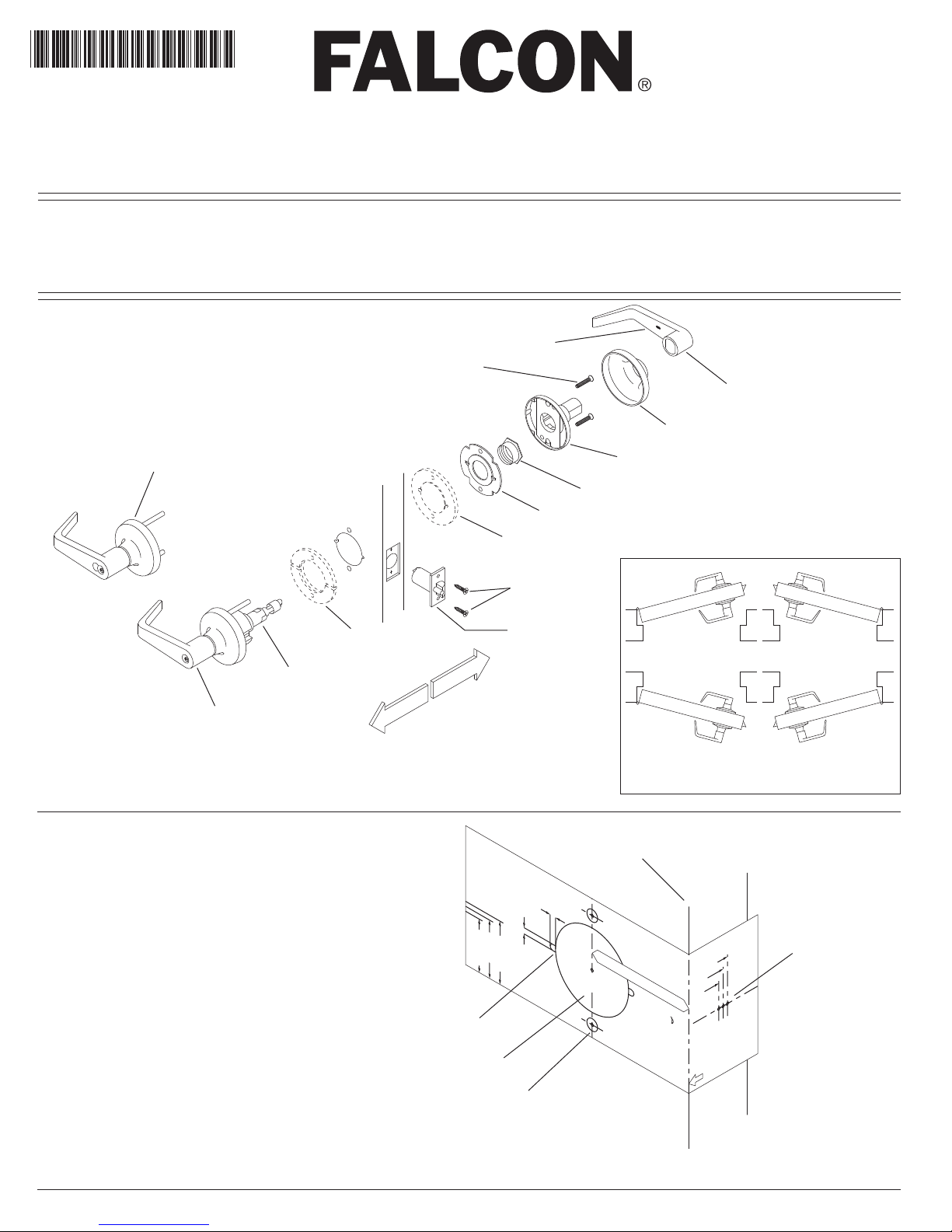
IMPORTANT: THIS LOCK IS NON-HANDED. LOCK IS FACTORY PACKED PREADJUSTED FOR 1³⁄₄" (45mm)
THICK DOORS. TO ADJUST LOCK FOR OTHER DOOR THICKNESS, SEE STEP 8, 9 & 10. SPACERS MUST BE
USED FOR DOORS THINNER THAN 1³⁄₄ " (45mm) THICK. FOR FUNCTIONS T351, T3 81 , T 561 AND T571,
SEE STEPS 16 (STANDARD CYLINDER) OR 17 (IC CORE) FOR TIMING INSTRUCTIONS.
Set Screw
¹⁄₄-20 x ¹⁄₄"
Mounting Screws
#10-32 x 1"
Rose
Inner Lever
Outer Trim Assembly
Interchangeable Core Cylinder
*Spacer
Chassis Assembly
Outer Trim Assembly
Standard Cylinder
OUTSIDE
LEFT HAND REVERSE SHOWN
STEP 1
MARK THE DOOR
Fold the template on the line indicated.
Place on HIGH EDGE of door bevel.
Position centerline of the template on heightline
(suggested height is 38" (965 mm) from floor).
A. Locate and mark center for 2¹⁄₈" (54 mm) hole.
B. Locate and mark positions for notches.
Caution: Notches must be horizontal.
C. Locate and mark center for two (2) ⁵⁄₁₆" (8 mm)
through-bolt holes.
D. Locate and mark center for 1" (25 mm) latch bolt hole
in the door edge.
Note: If steel frames are used, the latch centerline must
be in line with the center of the strike preparation.
INSIDE
*Spacer required for all
doors less than 1³⁄₄" thick.
RD )mm54
R
D )mm15("2
(
"
/
4
3
1
B) Mark Notches
A) Mark 2¹⁄₈" Hole
C) Mark Thru-Bolt Holes
Inner Mounting Plate
*Spacer
Attaching Screws
#8 Combination
Latch Assembly
x1/8"(3mm) DEEP
5/32"(4mm)
5/32"(4mm)
TNEMT
SUJDA GNIRETNE
R
D )
mm75("
LT
OF
T
/
4
1
2
C
RO
O
D
Flanged Nut
High Edge Of Bevel Door
HOLES.
THRU-BO
ALIGNMEN
ENSURE PROPER
RECOMMENDED TO
FIXTURE
030736-000-50 IS
USING DRILL
5/16"(8mm) HOLES
MARK CENTER FOR
Inner Trim Assembly
INSIDE
LEFT HAND
LEFT HAND REVERSE
OUTSIDE
DOOR HAND DETERMINED FROM OUTSIDE
T:
TAN
2 1/8"(54mm) HOLE
MARK CENTER FOR
TCH
2 3/4"(70mm) BACKSET
LA
LOCKS
2 1/4"(57mm)
BACKSET BEFORE DRILLING
CHECK LOCK FOR PROPER
2"(51mm)
IMPOR
(45mm)
1 3/4"
A
TCH
HOLE.
THICKNESS.
1"(25mm) DIA
IH
G
H
E
EGD
T–SERIES LEVER
INSTALLING
DRIL
L
FOR CORRECT DOOR
MARK CENTERLINE OF L
EDGE OF DOOR
PLACE ON HIGH
FOLD HERE &
TEMPLATE FOR
RIGHT HAND
RIGHT HAND REVERSE
D) Mark Latch Hole
Hint: For retrofitting of existing 2¹⁄₈" (54mm) holes, fold template in half to locate position for the two (2) ⁵⁄₁₆" (8mm) holes.
Page 2
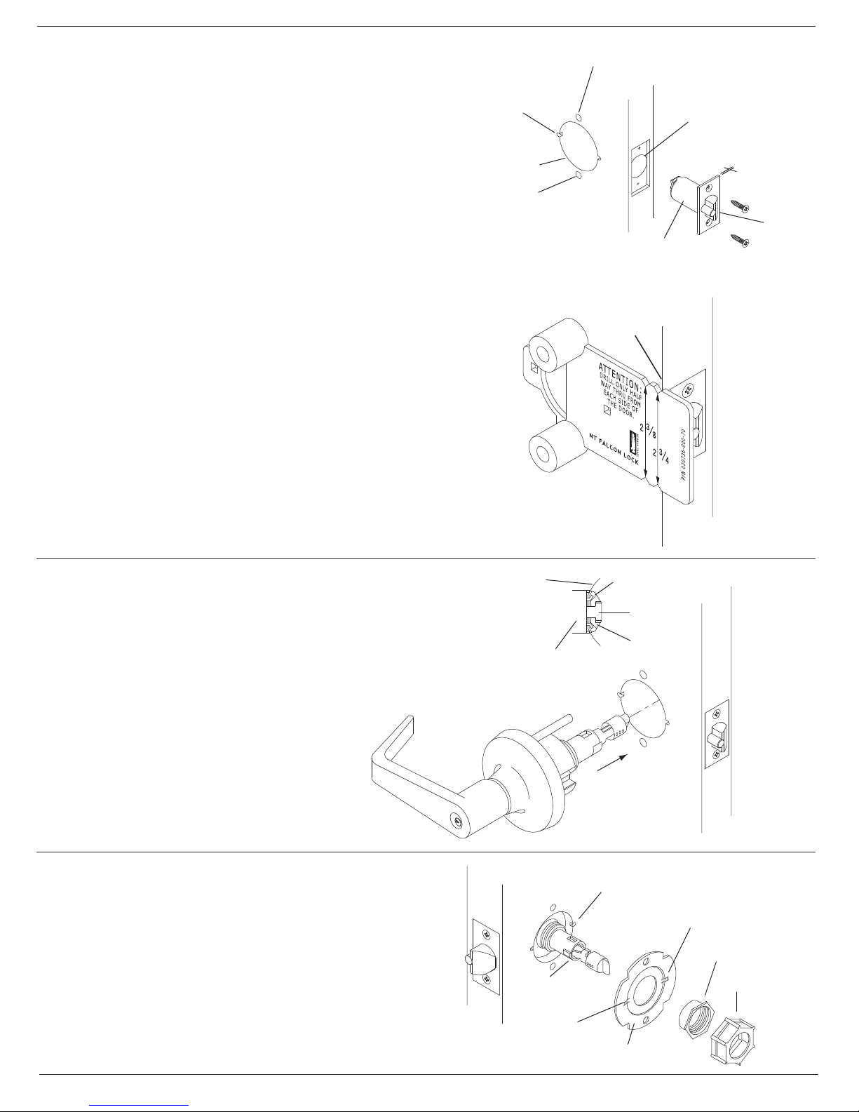
STEP 2
BORE HOLES: INSTALL LATCH
When drilling through the door, be careful not to damage the door finish.
A) 5/16" (8 mm)
Thru hole
A. Bore a 2¹⁄₈" (54 mm) hole and two (2) ⁵⁄₁₆" (8 mm) holes
from both sides of door to avoid splintering wood.
B. Bore a 1" (25 mm) hole into door edge. Using the latch faceplate
as a pattern, trace outline and mortise the door edge so the latch
is flush with door. If ³⁄₄" projection latch is to be installed see Step 19.
Note: For wood jambs, close the door and using a strike-locating tool
or other pointed object, mark the position of the hole in the jamb.
Open the door and drill 1" (25 mm) hole in the jamb a minimum of ³⁄₄"
19 mm) deep.
C. File two (2) ⁵⁄₃₂" (4 mm) x ⁵⁄₃₂" (4 mm) x ¹⁄₈" (3 mm) deep notches
into both sides of the door.
D. Insert the latch unit in the door, making certain that the latch bolt
bevel faces the direction of the closing door. Attach with two (2)
#8 combination screws provided.
Note: Use of a drill guide is recommended to ensure
straight and level holes.
IF USING THE FALCON OPTIONAL DRILL GUIDE
Install Drill Guide (M204-198) into the door. Make certain the
correct backset locators are even with door edge. Drill two (2) ⁵⁄₁₆" (8 mm)
holes from both sides to the center.
C) File Notches
A) 2-1/8" (54 mm)
Thru hole
A) 5/16" (8 mm)
Thru hole
B) 1" (25 mm) Hole
Latch Unit
Use faceplate as pattern for mortise.
Backset
Locator
5/32" (4 mm)
Latch
Bolt Bevel
Note: Drill guide replacement is recommended after ten (10) door preparations.
STEP 3
INSTALL CHASSIS AND OUTER TRIM ASSEMBLY
Note: For ease of installation, the lock should be in
the unlocked position.
Slide the chassis assembly into the door from outside
making sure that the lock housing engages the latc h
Chassis Assembly
prongs. Retractor must also engage the latch tail.
Important: The chassis assembly must be positioned
in the center of the door for proper operation.
See Step 9 for door thickness adjustment.
STEP 4
INSTALL INNER MOUNTING PLATE
A. Place the inner mounting plate onto the chassis assembly
making sure that the plate tabs engage the horizontal
notches in the door.
Lock Housing
Latch Case
Latch Prong
Latch Tail
Retractor
Outside of Door
Notches
Tab
Flanged Nut
B. Position the flanged nut over the chassis assembly and
tighten securely with hex wrench provided.
Black Hex Wrench Chassis Assembly
Tab
Inner Mounting Plate
Page 3

STEP 5
INSTALL INNER TRIM ASSEMBLY
Thru Post
Slide the inner trim assembly over the chassis spindle. Thru-posts will
engage the inner trim asembly on 1³⁄₄ " (45 mm) thick doors.
Secure to the door with two #10-32 x 1" machine screws provided.
STEP 6
INSTALL INNER LEVER
A. Position the rose over the inner trim assembly making
sure the rose detent engages the groove in the
spindle assembly.
B. Install the lever handle and tighten the set screw with
the hex key provided.
STOP! Test operation to be sure the latch bolt moves freely.
DO NOT FORCE. If the lockset does not operate properly, remove the
lockset from the door and check the door preparation and door thickness
adjustment. Go back to Step 3 to re-install the chassis.
Inner Trim Assembly
Thru Post
Chassis Spindle
Groove
Rose
Inner Trim Asssembly
Rose Detent
¹⁄₄-20 x ¹⁄₄"
Set Screw
Mounting Screws
#10-32 x 1"
Inner Lever
STEP 7 LOCATE AND INSTALL THE STRIKE
A. For wood jambs, center the strike latch opening over 1" (25 mm)
hole in jamb. Trace the outline around the strike on the door jamb.
B. Mortise the door jamb to accommodate the strike box
and the strike.
C. Insert the strike box if required and fasten the strike to the
jamb with #12 or #8 combination screws provided.
Caution: Deadlocking plunger of the latch bolt must not enter
opening in the strike plate.
the
Note: When the strike box is not used, the recess in the jamb must
be a minimum of ⁹⁄₁₆" (14 mm) deep to allow the latch bolt to extend
to its full projection.
STEP 8
INSTRUCTIONS FOR REMOVING OUTSIDE TRIM
A. Remove the outside trim retaining screw (A).
B. Slide the outside trim (B) from the chassis assembly.
C. See Step 9 for chassis adjustment procedure,
or Step 10 for spacer installation.
Mortise for
dust box
and strike
Mortise for
dust box
and strike
Jamb
ANSI Dust Box
ANSI Strike
#12 Combination Screw
Jamb
Dust Box
T-Strike
#8 Combination
Screw
B
A
D. Slide the outside trim (B) onto the chassis.
E. Replace the outside trim retaining screw (A).
Page 4

STEP 9
ADJUST LOCK FOR DOOR THICKNESS
The lock is factory packed preadjusted for 1³⁄₄" (45 mm) doors unless
special ordered.
A. Place the template provided against the retractor housing to find
the mark for door thickness.
"(45mm) DR
4
/
3
1
"(57mm) DR
4
/
1
2"(51mm) DR
2
x1/8"(3mm) DEEP
5/32"(4mm)
5/32"(4mm)
ALIGNMENT
PROPER
ENSURE
MENDED TO
RECOM-
DOOR CENTERING ADJUSTMENT
030736-000-50 IS
FIXTURE
USING DRILL
5/16"(8mm) HOLES
MARK CENTER FOR
LATCH
2 1/8"(54mm) HOLE
MARK CENTER FOR
BACKSET BEFORE DRILLING
CHECK LOCK FOR PROPER
IMPORTANT:
2"(51mm)
(45mm)
1 3/4"
2 3/4"(70mm) BACKSET
HIGH EDGE
LOCKS
T–SERIES LEVER
INSTALLING
TEMPLATE FOR
2 1/4"(57mm)
THICKNESS.
FOR CORRECT DOOR
MARK CENTERLINE OF LATCH
PLACE ON HIGH
FOLD HERE &
B. If adjustment is necessary, use hex wrench provided
and rotate flanged nut counterclockwise to adjust.
Again, use the template markings to measure adjustment
before installing lock on door.
Hint: Three full turns of the nut equals (=) ¹⁄₈" (3 mm) adjustment.
C. Pinch the button mount legs together and
move the cap to the desired position.
STEP 10 INSTALLING SPACER FOR DOORS THINNER
THAN 1³⁄₄ " (45 mm)
A. Remove the flanged nut with the black hex wrench
provided, and remove the outer mounting plate.
B. Place the spacer on over the outer chassis spindle
as shown.
C. Re-install the outer mounting plate and flanged nut.
Using the adjusting gage provided, adjust the flanged nut
for proper door thickness as shown.
D. Go back to Step 3 for chassis installation.
E. Place the second spacer over the inner chassis
spindle before installing the inner mounting plate
and flanged nut. Continue at Step 5.
Flanged Nut
Chassis Assembly
Black Hex Wrench
DOOR CENTERING
ADJUSTMENT GAGE
NT FALCON T-SERIES LEVER
LOCKS FOR DOORS LESS THAN
1 3/4 (45mm) THICK
NT FALCON LOCK
1 3/4 (45mm)
1 1/4 (32mm)
1 1/2 (38mm)
P/N 030793-001-70
PRINTED IN U.S.A.
Spacer
Outer Mounting Plate
Outer Mounting Plate
Gage
Spacer
Flanged Nut
Chassis Assembly
Button Mount Legs
2¹⁄₄"
(57 mm)
Inner Mounting Plate
Inside
Outside
Cap
2"
(51 mm)
(45 mm)
Flanged Nut
Spacer
1³⁄₄"
STEP 11
TO REMOVE ALL LEVERS WITH INTERCHANGEABLE CORE CYLINDERS
A. Insert the control key into the core and rotate 15 degrees clockwise.
Pull the key to remove the core.
B. Insert a screwdriver into the “figure 8” core hole and into the
lever retainer.
C. Depress the retainer and slide the lever off the spindle.
TO RE-INSTALL THE LEVER
D. Slide the lever over the spindle and push on over the retainer.
E. Pull on the lever to be sure the retainer is engaged with the lever.
F. Re-install the core with the tailpiece pushed into the core.
Control Key
A
B
Push
Retainer
Page 5

STEP 12
IC CORE AND TAILPIECE
Be certain to use the correct tailpiece with the core.
Six pin cores should only use the "6P" tailpiece.
Seven pin cores should only use the "7P" tailpiece.
STEP 13
TO REMOVE ALL CYLINDER LEVERS
(Except Interchangeable Core)
A. Insert the key and rotate clockwise
approximately 60 degrees.
B. Depress lever retainer with tool provided.
C. Slide lever off spindle.
TO RE-INSTALL THE LEVER
D. Insert cylinder into spindle.
E. Slide lever onto spindle.
F. Insert key into cylinder and rotate clockwise approximately
60 degrees and push lever over retainer.
G. Pull on lever to be sure the retainer is engaged with the lever.
FALCON
6 Pin Core
C
FALCON
7 Pin Core
B
A
STEP 14 TAILPIECE INSTALLATION
For proper function of the lock, the tailpiece must be
installed correctly.
All T-Series tailpieces should be installed
VERTICALLY in the cylinder.
STEP 15
SINGLE DUMMY TRIM, T12
A. Using the template described in Step 1,
locate and mark the center for
two (2) mounting holes.
B. For Wood Door - Drill two (2) pilot holes
⁵⁄₃₂" (4 mm) x ⁷⁄₈" (22 mm) deep for #12 wood screws.
For Metal Door - Drill and tap two (2) holes
for #12-24 machine screws.
C. Position the spindle assembly over the
mounting holes and secure to the door
with the screws provided.
D. See Step 6 for lever installation.
Cylinder
Spring
Inside of Door
Pin
Screws for Metal Doors
#12-24 x ³⁄₄"
Screws for Wood Doors
#12 x 1¹⁄₂"
Tailpiece
Cap
Inner Trim Assembly
Groove
Page 6

STEP 16
TIMING INSTRUCTIONS FOR STANDARD CYLINDER LOCKS
T351, T381, T561, T571
A. If the cylinder and lever are installed, refer to Step 13 for
lever removal instructions.
B. Using a thin flat screw driver, turn the action bar slot clockwise
(cw) until it stops at about 2:00.
FOR THE FOLLOWING FUNCTIONS:
RH Shown
Action
bar
slot
C. Then turn the action bar counterclockwise (ccw) to the 9:00
position. NOTE: There is no physical stop at this location.
D. With the key out, install the standard cylinder into the spindle.
E. Refer to Step 13 for lever re-installation.
F. Operate the key to test for proper operation.
STEP 17 TIMING INSTRUCTIONS FOR IC CORE LOCKS
T351, T381, T561, T571
FOR THE FOLLOWING FUNCTIONS:
A. If the core is installed, refer to Step 11 for IC core removal instructions.
B. Using a thin flat screw driver, turn the action bar slot clockwise
(cw) until it stops at about 11:00.
C. Then turn the action bar counterclockwise (ccw) to the 7:00
position. NOTE: There is no physical stop is at this location.
D. Using the control key, insert IC core into the lever and spindle.
E. Remove the control key.
F. Operate the key to test for proper operation.
STEP 18 TAILPIECE INSTALLATION INSTRUCTIONS FOR T381 FUNCTION
Door
edge
RH Shown
Action
bar
slot
Door
edge
SEE STEP 14 FOR STANDARD CYLINDER
LONG TAILPIECE SHORT TAILPIECE
TAILPIECE INSTALLATION
OUTER STANDARD CYLINDER ASSEMBLY
CLUTCH
ON
OUTSIDE
SEE STEP 12 FOR IC CORE
LONG TAILPIECE SHORT TAILPIECE
TAILPIECE INSTALLATION
OUTER IC CORE ASSEMBLY INNER IC CORE ASSEMBLY
STEP 19
INSTALLATION INSTRUCTIONS FOR OPTIONAL ³⁄₄" PROJECTION LATCH
A. Determine the hand of the door.
B. On the side closest to the door stop, remove the shaded area as shown.
Use a standard rotary file ³⁄₈" diameter maximum.
C. Try the latch for fit and function.
D. Secure the latch with two (2) #8-32 machine screws provided.
INNER STANDARD CYLINDER ASSEMBLY
Door stop
on this side
1"
MIN
REF
1¹⁄₁₆" MIN REF
800-266-4456©2010 Schlage Lock Company Printed in Country 030794-000-70 Rev. 05/10-d
 Loading...