

Page 1
T-Series
Service manual
Page 2

Page 3

Contents
5 Introduction
6 Lock Assembly Index
8 Chassis assemblies
9 Passage latchset
10 Privacy hospital lock
11 Closet lock
12 Closet lock – IC
13 Classroom security lock
14 Classroom security lock – IC
15 Asylum lock
16 Asylum lock – IC
17 Entry lock
18 Entry lock – IC
19 Entry/oce lock
20 Entry/oce lock – IC
21 Oce lock
22 Oce lock – IC
23 Classroom lock
24 Classroom lock – IC
25 Dormitory lock
26 Dormitory lock – IC
27 Storeroom lock
28 Storeroom lock – IC
29 Storeroom lock (electrified – fail safe)
30 Storeroom lock (electrified – fail safe) – IC
31 Storeroom lock (electrified – fail secure)
32 Storeroom lock (electrified – fail secure) – IC
33 Trim assemblies
34 Passage latchset
35 Privacy hospital lock
36 Privacy lock
37 Closet lock
38 Classroom security lock
39 Asylum lock
40 Entry lock
41 Entry/oce lock
42 Oce lock
43 Classroom lock
44 Dormitory lock
45 Storeroom lock
46 Storeroom lock (electrified – fail safe)
47 Storeroom lock (electrified – fail secure)
48 Parts and Accessories
48 Standard cylinders
49 IC cylinders
50 Spindles
51 Spring cage replacement kits
52 Levers
53 Latches
54 Other Accessories
54 Strikes
54 Dust boxes
55 Warranty
Page 4

Page 5
Introduction
Introduction
This manual contains a complete listing of T-Series (Grade 1) cylindrical lock parts and assemblies manufactured by the
Falcon Lock Company. This edition lists components of T-Series locks manufactured aer July 2007.
Exploded views of each lock chassis and trim assemblies are provided with an accompanying chart to identify parts for
replacement purposes. In addition, this manual provides general cylinder information, many auxiliary components of the
T-Series cylindrical locks and installation instructions.
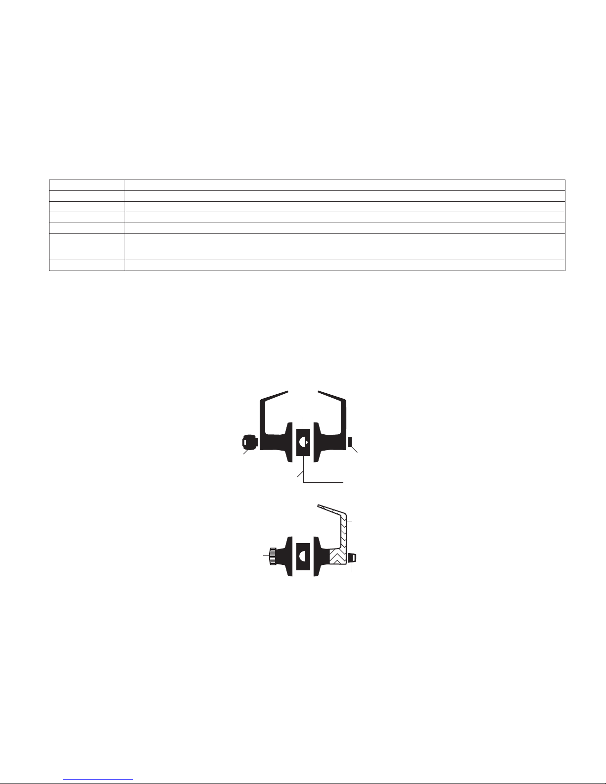
Standard features*
Certications ANSI A156 .2, Series 4000, Grade 1, UL Listed for 3-hour re door.
Latch
Strike
Backset
Cylinder 6-Pin solid brass, keyed 5-pin, Falcon G keyway, keyed different (KD)
Door Range
Keys Two nickel silver cut keys per lock, keyed 5-pin, Falcon G keyway
* Locks are furnished with standard features unless otherwise specied.
Lock assembly drawing index
The lock assembly drawing index provides visual representations and textual descriptions of available functions. Page
numbers for full trim and chassis drawings are referenced.
Z\,” x 2Z\v”, Square corner faceplate, 1” housing diameter, Z\x” throw.
1
Z\v” x 4M\,”, ANSI, Square corner, no box.
2
C\v”
1
C\v” – 2Z\,” standard
Outside Inside
Deadlatch
Key
Electrified
Knurled Knob
Springlatch
Push button
Fixed Lever
Tu rn/push button
Falcon • T-Series service manual • 5
Page 6
Lock Assembly Index
Lock Assembly Index
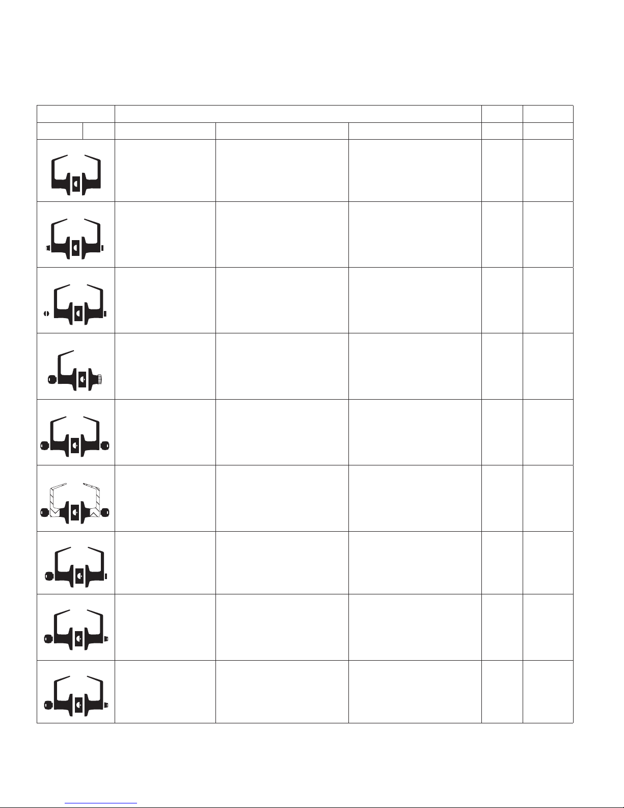
Function ANSI A156.2, 1996, Series 4000, Grade 1 Trim Chassis
Falcon ANSI Description Outside function Inside function
T101 F75
Passage/closet latch Lever is always unlocked. Lever is always unlocked and is
always free for immediate egress.
34 9
T291
T301 F76
T351
T381 F88
T411 F87
Privacy hospital lock Unlocked from outside by turning
emergency turn-button.
Privacy lock Can be opened from outside with
small screwdriver or emergency
release tool.
Closet lock Can be locked with key. Knurled knob free for immediate
Classroom security lock Outside lever locked or unlocked by
key in either lever.
Asylum lock Lever is xed. Entrance by key only. Lever is xed. Exit by key only.
Push-button locks outside lever.
Turning inside lever or closing door
releases button. Inside lever is
always free for immediate egress.
Push-button locks outside lever.
Turning inside lever or closing door
releases button. Inside lever is
always free for immediate egress.
egress unless outside lever locked
with key.
Key locks or unlocks outside lever.
Inside lever is always unlocked and
is always free for immediate
egress.
35 10
36 10
37 11
12 (IC)
38 13
14 (IC)
39 15
16 (IC)
T501 F82
T511 F109
T521 F81
NOTE: Any function with deadlatch locks latchbolt when door is closed.
6 • Falcon • T-Series service manual
Entry lock Lever is unlocked with key when
Entry/oce lock Key retracts latch when button
Oce lock Key retracts latch when button
push-button is pushed.
pushed and turned. Lever is
unlocked with key when pushbutton is pushed.
turned.
Push-button locks outside lever.
Turning inside lever releases
button. Inside lever is always free
for immediate egress.
Turn/push-button: pushing and
turning button locks outside lever
until manually unlocked. Push button: pushing button locks
outside lever until unlocked by
turning inside lever. Inside always
free for immediate egress.
Turning button locks outside lever
until manually unlocked. Inside
always free for immediate egress.
40 17
18 (IC)
41 19
20 (IC)
42 21
22 (IC)
Page 7
Lock Assembly Index
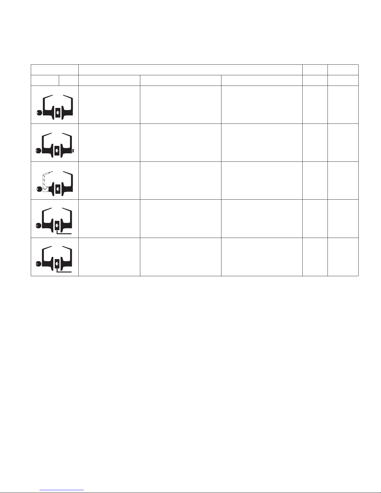
Function ANSI A156.2, 1996, Series 4000, Grade 1 Trim Chassis
Falcon ANSI Description Outside function Inside function
T561 F84
Classroom lock Outside lever locked or unlocked
by key.
Inside lever is always unlocked and
always free for immediate egress.
43 23
24 (IC)
T571 F90
T581 F86
T851
T881
NOTE: Any function with deadlatch locks latchbolt when door is closed.
Dormitory lock Locked or unlocked
Storeroom lock Lever is xed. Entrance by key only. Inside lever is always unlocked and
Storeroom lock
(electried – fail safe)
Storeroom lock
(electried – fail secure)
by key. When locked by key it can
only be unlocked by key.
Lever is continuously locked
electrically. Unlocked by switch or
power failure. When locked, key
retracts latch.
Lever is continuously locked
mechanically until unlocked by
electric current. When locked, key
retracts latch.
Push-button locks outside lever.
Turning lever or closing door
releases button. Inside lever is
always unlocked and is always
free for immediate egress.
is always free for immediate
egress.
Inside lever is always unlocked and
is always free for immediate
egress.
Inside lever is always unlocked and
is always free for immediate
egress.
44 25
26 (IC)
45 27
28 (IC)
46 29
30 (IC)
47 31
32 (IC)
Falcon • T-Series service manual • 7
Page 8

Chassis assemblies
9 Passage latchset
10 Privacy hospital lock
11 Closet lock
12 Closet lock – IC
13 Classroom security lock
14 Classroom security lock – IC
15 Asylum lock
16 Asylum lock – IC
17 Entry lock
18 Entry lock – IC
19 Entry/oce lock
20 Entry/oce lock – IC
21 Oce lock
22 Oce lock – IC
23 Classroom lock
24 Classroom lock – IC
25 Dormitory lock
26 Dormitory lock – IC
27 Storeroom lock
28 Storeroom lock – IC
29 Storeroom lock (electrified – fail safe)
30 Storeroom lock (electrified – fail safe) – IC
31 Storeroom lock (electrified – fail secure)
32 Storeroom lock (electrified – fail secure) – IC
8 • Falcon • T-Series service manual
Page 9

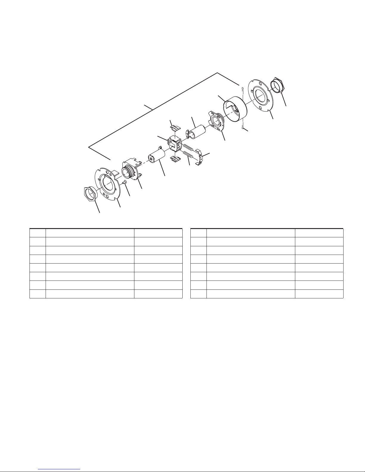
Chassis assemblies
2
2
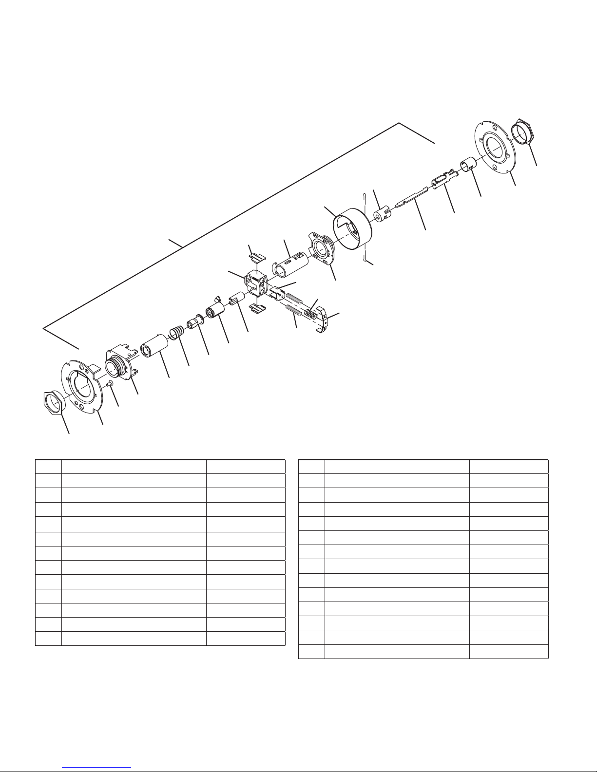
Passage latchset
T101
12
1
8 (2)
7
6
5
4
3
No. Description Part number
1 Chassis assembly, T101 A30761-000-00
2 Flanged nut (2) 030726-000-30
3 Outer mounting plate 030712-001-30
4 #8-32 x C\,” self tap screw 031533-006-30
5 Hub and housing assembly A30746-000-00
6 Spindle 030733-000-55
7 Retractor 022106-002-55
6
14
13 (2)
11
10
9 (2)
No. Description Part number
8 Retractor insert (2) 022986-001-50
9 Retractor spring (2) 022108-001-60
10 Retractor spring retainer 022112-000-30
11 Hub and plate assembly A30747-000-00
12 Housing case 022114-000-30
13 Cotter pin (2) 002893-000-60
14 Inner mounting plate 030712-000-30
Falcon • T-Series service manual • 9
Page 10
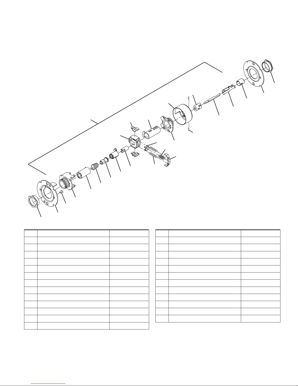
Chassis assemblies
2
2
Privacy hospital lock
T291/T301
1
8 (2)
7
19
18
17
16
15
5
4
3
No. Description Part number
1 Chassis assembly, T291/T301 A30765-000-00
2 Flanged nut (2) 030726-000-30
3 Outer mounting plate 030712-001-30
4
5 Hub and housing assembly A30746-000-00
6 Spindle 030733-000-55
7 Retractor 022106-002-55
8 Retractor insert (2) 022986-001-50
9 Retractor spring (2) 022108-001-60
10 Retractor spring retainer 022112-000-30
11 Hub and plate assembly A30747-000-00
12 Housing case 022114-000-30
#8-32 x
C\,” self tap screw
031533-006-30
22
12
25
24
6
23
13 (2)
20
11
21
10
9 (2)
No. Description Part number
13 Cotter pin (2) 002893-000-60
14 Inner mounting plate 030712-000-30
15 Spindle, 1 ear, outer 030732-005-30
16 Clutch spring 030709-000-60
17 Clutch driver 030716-001-30
18 Key spindle std 030718-000-30
19 Push actuator 030711-000-30
20 Slide catch 022105-000-30
21 Slide catch spring 012107-001-60
22 Push button sleeve 022134-000-50
23 Dogging bar 030722-000-30
24 Push/turn button mount 030731-000-30
25 Push button cap 030728-000*
14
10 • Falcon • T-Series service manual
Page 11
Chassis assemblies
2
2
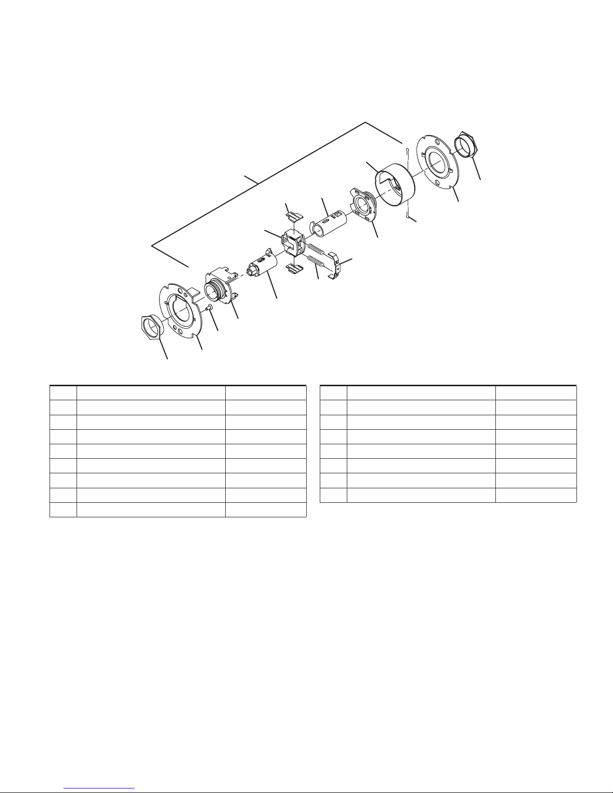
Closet lock
T351
12
1
8 (2)
7
26
5
4
3
No. Description Part number
1 Chassis assembly, T351/T561 A30758-000-00
2 Flanged nut (2) 030726-000-30
3 Outer mounting plate 030712-001-30
4 #8-32 x C\,” self tap screw 031533-006-30
5 Hub and housing assembly A30746-000-00
6 Spindle 030733-000-55
7 Retractor 022106-002-55
8 Retractor insert (2) 022986-001-50
6
14
13 (2)
11
10
9 (2)
No. Description Part number
9 Retractor spring (2) 022108-001-60
10 Retractor spring retainer 022112-000-30
11 Hub and plate assembly A30747-000-00
12 Housing case 022114-000-30
13 Cotter pin (2) 002893-000-60
14 Inner mounting plate 030712-000-30
26 Key spindle assembly, std A30780-000-30
Falcon • T-Series service manual • 11
Page 12
Chassis assemblies
2
2
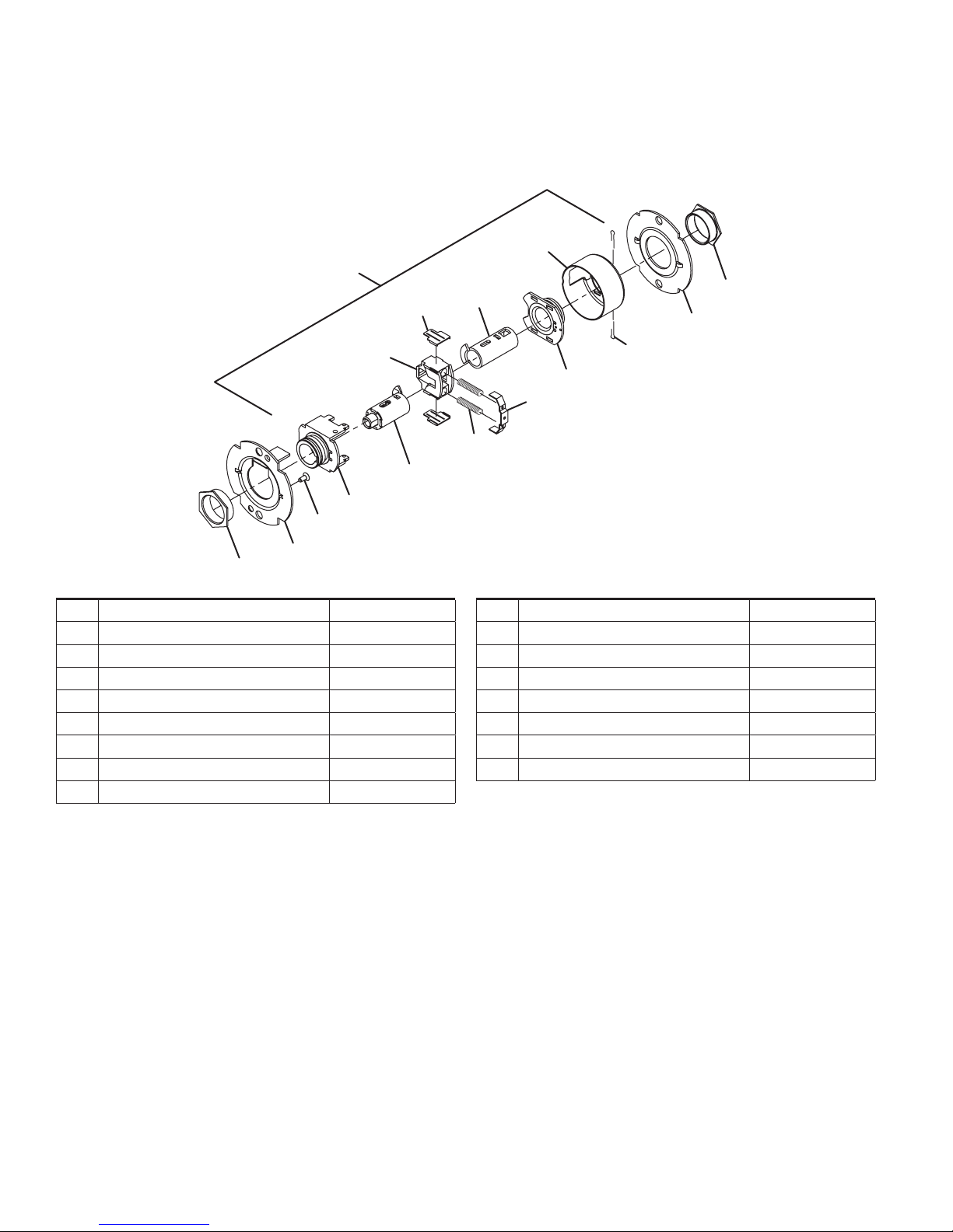
Closet lock – IC
T351
12
1
8 (2)
7
27
5
4
3
No. Description Part number
1 Chassis assembly, T351/T561-IC A30758-001-00
2 Flanged nut (2) 030726-000-30
3 Outer mounting plate 030712-001-30
4 #8-32 x C\,” self tap screw 031533-006-30
5 Hub and housing assembly A30746-000-00
6 Spindle 030733-000-55
7 Retractor 022106-002-55
8 Retractor insert (2) 022986-001-50
6
14
13 (2)
11
10
9 (2)
No. Description Part number
9 Retractor spring (2) 022108-001-60
10 Retractor spring retainer 022112-000-30
11 Hub and plate assembly A30747-000-00
12 Housing case 022114-000-30
13 Cotter pin (2) 002893-000-60
14 Inner mounting plate 030712-000-30
27 Key spindle assembly, ic A30780-001-30
12 • Falcon • T-Series service manual
Page 13

Chassis assemblies
2
2
Classroom security lock
T381
12
1
7
18
17
16
15
5
4
3
No. Description Part number
1 Chassis assembly, T381 A30767-000-00
2 Flanged nut (2) 030726-000-30
3 Outer mounting plate 030712-001-30
4 #8-32 x C\,” self tap screw 031533-006-30
5 Hub and housing assembly A30746-000-00
7 Retractor 022106-002-55
8 Retractor insert (2) 022986-001-50
9 Retractor spring (2) 022108-001-60
10 Retractor spring retainer 022112-000-30
11 Hub and plate assembly A30747-000-00
28
8 (2)
30
13 (2)
11
10
9 (2)
19
No. Description Part number
12 Housing case 022114-000-30
13 Cotter pin (2) 002893-000-60
14 Inner mounting plate 030712-000-30
15 Spindle, 1 ear, outer 030732-005-30
16 Clutch spring 030709-000-60
17 Clutch driver 030716-001-30
18 Key spindle std 030718-000-30
19 Push actuator 030711-000-30
28 IS key spindle assembly, std A30913-000-00
30 Connecting rod 030734-000-30
14
Falcon • T-Series service manual • 13
Page 14
Chassis assemblies
2
2
Classroom security lock – IC
T381
12
1
7
17
16
15
5
4
3
No. Description Part number
1 Chassis assembly, T381 A30767-001-00
2 Flanged nut (2) 030726-000-30
3 Outer mounting plate 030712-001-30
4 #8-32 x C\,” Self tap screw 031533-006-30
5 Hub and housing assembly A30746-000-00
7 Retractor 022106-002-55
8 Retractor insert (2) 022986-001-50
9 Retractor spring (2) 022108-001-60
10 Retractor spring retainer 022112-000-30
11 Hub and plate assembly A30747-000-00
31
29
8 (2)
30
13 (2)
11
10
9 (2)
19
No. Description Part number
12 Housing case 022114-000-30
13 Cotter pin (2) 002893-000-60
14 Inner mounting plate 030712-000-30
15 Spindle, 1 ear, outer 030732-005-30
16 Clutch spring 030709-000-60
17 Clutch driver 030716-001-30
19 Push actuator 030711-000-30
29 IS key spindle assembly, IC A30913-001-00
30 Connecting rod 030734-000-30
31 Key Spindle, IC 030718-001-30
14
14 • Falcon • T-Series service manual
Page 15
Chassis assemblies
2
2
Asylum lock
T411
12
1
7
32
5
4
3
No. Description Part number
1 Chassis assembly, T411 A30769-000-00
2 Flanged nut (2) 030726-000-30
3 Outer mounting plate 030712-001-30
4 #8-32 x C\,” Self tap screw 031533-006-30
5 Hub and housing assembly A30746-000-00
7 Retractor 022106-002-55
8 Retractor insert (2) 022986-001-50
8 (2)
32
14
13 (2)
11
10
9 (2)
No. Description Part number
9 Retractor spring (2) 022108-001-60
10 Retractor spring retainer 022112-000-30
11 Hub and plate assembly A30747-000-00
12 Housing case 022114-000-30
13 Cotter pin (2) 002893-000-60
14 Inner mounting plate 030712-000-30
32 Spindle, 2 ear, std 030732-000-30
Falcon • T-Series service manual • 15
Page 16

Chassis assemblies
2
2
Asylum lock – IC
T411
12
1
8 (2)
7
33
5
4
3
No. Description Part number
1 Chassis assembly, T411-IC A30769-001-00
2 Flanged nut (2) 030726-000-30
3 Outer mounting plate 030712-001-30
4 #8-32 x C\,” Self tap screw 031533-006-30
5 Hub and housing assembly A30746-000-00
7 Retractor 022106-002-55
8 Retractor insert (2) 022986-001-50
33
14
13 (2)
11
10
9 (2)
No. Description Part number
9 Retractor spring (2) 022108-001-60
10 Retractor spring retainer 022112-000-30
11 Hub and plate assembly A30747-000-00
12 Housing case 022114-000-30
13 Cotter pin (2) 002893-000-60
14 Inner mounting plate 030712-000-30
33 Spindle, 2 ear, IC 030732-001-30
16 • Falcon • T-Series service manual
Page 17
Chassis assemblies
2
2
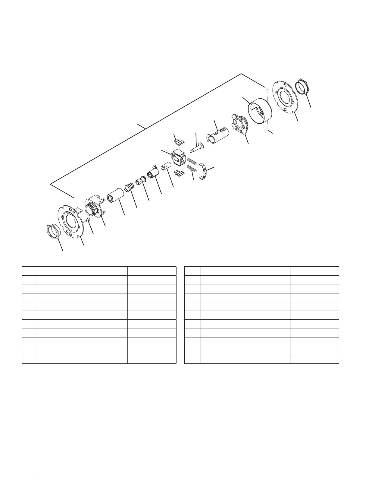
Entry lock
T501
1
8 (2)
7
19
18
17
16
15
5
4
3
No. Description Part number
1 Chassis assembly, T501 A30773-000-00
2 Flanged nut (2) 030726-000-30
3 Outer mounting plate 030712-001-30
4 #8-32 x C\,” Self tap screw 031533-006-30
5 Hub and housing assembly A30746-000-00
6 Spindle 030733-000-55
7 Retractor 022106-002-55
8 Retractor insert (2) 022986-001-50
9 Retractor spring (2) 022108-001-60
10 Retractor spring retainer 022112-000-30
11 Hub and plate assembly A30747-000-00
12 Housing case 022114-000-30
13 Cotter pin (2) 002893-000-60
22
12
24
6
23
13 (2)
34
11
21
10
9 (2)
No. Description Part number
14 Inner mounting plate 030712-000-30
15 Spindle, 1 ear, outer 030732-005-30
16 Clutch spring 030709-000-60
17 Clutch driver 030716-001-30
18 Key spindle std 030718-000-30
19 Push actuator 030711-000-30
21 Slide catch spring 012107-001-60
22 Push button sleeve 022134-000-50
23 Dogging Bar 030722-000-30
24 Push/turn button mount 030731-000-30
25 Push button cap 030728-000*
34 Short slide catch 022104-000-30
14
25
Falcon • T-Series service manual • 17
Page 18

Chassis assemblies
2
2
Entry lock – IC
T501
1
8 (2)
7
19
31
17
16
15
5
4
3
No. Description Part number
1 Chassis assembly, T501-IC A30773-001-00
2 Flanged nut (2) 030726-000-30
3 Outer mounting plate 030712-001-30
4 #8-32 x C\,” Self tap screw 031533-006-30
5 Hub and housing assembly A30746-000-00
6 Spindle 030733-000-55
7 Retractor 022106-002-55
8 Retractor insert (2) 022986-001-50
9 Retractor spring (2) 022108-001-60
10 Retractor spring retainer 022112-000-30
11 Hub and plate assembly A30747-000-00
12 Housing case 022114-000-30
13 Cotter pin (2) 002893-000-60
22
12
24
6
23
13 (2)
34
11
21
10
9 (2)
No. Description Part number
14 Inner mounting plate 030712-000-30
15 Spindle, 1 ear, outer 030732-005-30
16 Clutch spring 030709-000-60
17 Clutch driver 030716-001-30
19 Push actuator 030711-000-30
21 Slide Catch Spring 012107-001-60
22 Push Button Sleeve 022134-000-50
23 Dogging Bar 030722-000-30
24 Push/turn button mount 030731-000-30
25 Push button cap 030728-000*
31 Key spindle, IC 030718-001-30
34 Short slide catch 022104-000-30
14
25
18 • Falcon • T-Series service manual
Page 19

Chassis assemblies
2
2
Entry/oce lock
T511
1
8 (2)
7
19
18
17
16
15
5
4
3
No. Description Part number
1 Chassis assembly, T511 A30756-000-00
2 Flanged nut (2) 030726-000-30
3 Outer mounting plate 030712-001-30
4 #8-32 x C\,” Self tap screw 031533-006-30
5 Hub and housing assembly A30746-000-00
6 Spindle 030733-000-55
7 Retractor 022106-002-55
8 Retractor insert (2) 022986-001-50
9 Retractor spring (2) 022108-001-60
10 Retractor spring retainer 022112-000-30
11 Hub and plate assembly A30747-000-00
12 Housing case 022114-000-30
13 Cotter pin (2) 002893-000-60
35
12
36
24
6
23
13 (2)
34
11
21
10
9 (2)
No. Description Part number
14 Inner mounting plate 030712-000-30
15 Spindle, 1 ear, outer 030732-005-30
16 Clutch spring 030709-000-60
17 Clutch driver 030716-001-30
18 Key spindle std 030718-000-30
19 Push actuator 030711-000-30
21 Slide Catch Spring 012107-001-60
23 Dogging Bar 030722-000-30
24 Push/Turn Button Mount 030731-000-30
34 Short Slide Catch 022104-000-30
35 Turn Button Sleeve 022133-000-50
36 Turn Button Cap 030727-000*
14
Falcon • T-Series service manual • 19
Page 20

Chassis assemblies
2
2
Entry/oce lock – IC
T511
1
8 (2)
7
19
31
17
16
15
5
4
3
No. Description Part number
1 Chassis assembly, T511-IC A30756-001-00
2 Flanged nut (2) 030726-000-30
3 Outer mounting plate 030712-001-30
4 #8-32 x C\,” Self tap screw 031533-006-30
5 Hub and housing assembly A30746-000-00
6 Spindle 030733-000-55
7 Retractor 022106-002-55
8 Retractor insert (2) 022986-001-50
9 Retractor spring (2) 022108-001-60
10 Retractor spring retainer 022112-000-30
11 Hub and plate assembly A30747-000-00
12 Housing case 022114-000-30
13 Cotter pin (2) 002893-000-60
35
12
36
24
6
23
13 (2)
34
11
21
10
9 (2)
No. Description Part number
14 Inner mounting plate 030712-000-30
15 Spindle, 1 ear, outer 030732-005-30
16 Clutch spring 030709-000-60
17 Clutch driver 030716-001-30
19 Push actuator 030711-000-30
21 Slide catch spring 012107-001-60
23 Dogging bar 030722-000-30
24 Push/turn button mount 030731-000-30
31 Key spindle, IC 030718-001-30
34 Short slide catch 022104-000-30
35 Turn button sleeve 022133-000-50
36 Turn button cap 030727-000*
14
20 • Falcon • T-Series service manual
Page 21

Chassis assemblies
2
2
Oce lock
T521
1
8 (2)
7
19
18
17
16
15
5
4
3
No. Description Part number
1 Chassis assembly, T521 A30748-000-00
2 Flanged nut (2) 030726-000-30
3 Outer mounting plate 030712-001-30
4 #8-32 x C\,” Self tap screw 031533-006-30
5 Hub and housing assembly A30746-000-00
6 Spindle 030733-000-55
7 Retractor 022106-002-55
8 Retractor insert (2) 022986-001-50
9 Retractor spring (2) 022108-001-60
10 Retractor spring retainer 022112-000-30
11 Hub and plate assembly A30747-000-00
12 Housing case 022114-000-30
6
9 (2)
35
14
12
36
24
23
13 (2)
11
10
No. Description Part number
13 Cotter pin (2) 002893-000-60
14 Inner mounting plate 030712-000-30
15 Spindle, 1 ear, outer 030732-005-30
16 Clutch spring 030709-000-60
17 Clutch driver 030716-001-30
18 Key spindle, std 030718-000-30
19 Push actuator 030711-000-30
23 Dogging bar 030722-000-30
24 Push/turn button mount 030731-000-30
35 Turn button sleeve 022133-000-50
36 Turn button cap 030727-000*
Falcon • T-Series service manual • 21
Page 22

Chassis assemblies
2
2
Oce lock – IC
T521
1
8 (2)
7
19
31
17
16
15
5
4
3
No. Description Part number
1 Chassis assembly, T521-IC A30748-001-00
2 Flanged nut (2) 030726-000-30
3 Outer mounting plate 030712-001-30
4 #8-32 x C\,” Self tap screw 031533-006-30
5 Hub and housing assembly A30746-000-00
6 Spindle 030733-000-55
7 Retractor 022106-002-55
8 Retractor insert (2) 022986-001-50
9 Retractor spring (2) 022108-001-60
10 Retractor spring retainer 022112-000-30
11 Hub and plate assembly A30747-000-00
12 Housing case 022114-000-30
6
9 (2)
35
14
12
36
24
23
13 (2)
11
10
No. Description Part number
13 Cotter pin (2) 002893-000-60
14 Inner mounting plate 030712-000-30
15 Spindle, 1 ear, outer 030732-005-30
16 Clutch spring 030709-000-60
17 Clutch driver 030716-001-30
19 Push actuator 030711-000-30
23 Dogging bar 030722-000-30
24 Push/turn button mount 030731-000-30
31 Key spindle, IC 030718-001-30
35 Turn button sleeve 022133-000-50
36 Turn button cap 030727-000*
22 • Falcon • T-Series service manual
Page 23

Chassis assemblies
2
2
Classroom lock
T561
12
1
8 (2)
7
26
5
4
3
No. Description Part number
1 Chassis assembly, T351/T561 A30758-000-00
2 Flanged nut (2) 030726-000-30
3 Outer mounting plate 030712-001-30
4 #8-32 x C\,” Self tap screw 031533-006-30
5 Hub and housing assembly A30746-000-00
6 Spindle 030733-000-55
7 Retractor 022106-002-55
8 Retractor insert (2) 022986-001-50
6
14
13 (2)
11
10
9 (2)
No. Description Part number
9 Retractor spring (2) 022108-001-60
10 Retractor spring retainer 022112-000-30
11 Hub and plate assembly A30747-000-00
12 Housing case 022114-000-30
13 Cotter pin (2) 002893-000-60
14 Inner mounting plate 030712-000-30
26 Key spindle assembly, std A30780-000-30
Falcon • T-Series service manual • 23
Page 24

Chassis assemblies
2
2
Classroom lock – IC
T561
12
1
8 (2)
7
27
5
4
3
No. Description Part number
1 Chassis assembly, T351/T561-IC A30758-001-00
2 Flanged nut (2) 030726-000-30
3 Outer mounting plate 030712-001-30
4 #8-32 x C\,” Self tap screw 031533-006-30
5 Hub and housing assembly A30746-000-00
6 Spindle 030733-000-55
7 Retractor 022106-002-55
8 Retractor insert (2) 022986-001-50
6
14
13 (2)
11
10
9 (2)
No. Description Part number
9 Retractor spring (2) 022108-001-60
10 Retractor spring retainer 022112-000-30
11 Hub and plate assembly A30747-000-00
12 Housing case 022114-000-30
13 Cotter pin (2) 002893-000-60
14 Inner mounting plate 030712-000-30
27 Key spindle assembly, IC A30780-001-30
24 • Falcon • T-Series service manual
Page 25

Chassis assemblies
2
2
Dormitory lock
T571
1
8 (2)
6
7
37
5
4
3
No. Description Part number
1 Chassis assembly, T571 A30759-000-00
2 Flanged nut (2) 030726-000-30
3 Outer mounting plate 030712-001-30
4 #8-32 x C\,” Self tap screw 031533-006-30
5 Hub and housing assembly A30746-000-00
6 Spindle 030733-000-55
7 Retractor 022106-002-55
8 Retractor insert (2) 022986-001-50
9 Retractor spring (2) 022108-001-60
10 Retractor spring retainer 022112-000-30
11 Hub and plate assembly A30747-000-00
20
9 (2)
22
14
12
25
24
23
13 (2)
11
21
10
No. Description Part number
12 Housing case 022114-000-30
13 Cotter pin (2) 002893-000-60
14 Inner mounting plate 030712-000-30
20 Slide catch 022105-000-30
21 Slide catch spring 012107-001-60
22 Push button sleeve 022134-000-50
23 Dogging bar 030722-000-30
24 Push/turn button mount 030731-000-30
25 Push button cap 030728-000*
37 Key spindle assembly, T571, std A30915-000-00
*= Finish or specify nish on all
Falcon • T-Series service manual • 25
Page 26

Chassis assemblies
2
2
Dormitory lock – IC
T571
1
8 (2)
6
7
9 (2)
38
5
4
3
No. Description Part number
1 Chassis assembly, T571-IC A30759-001-00
2 Flanged nut (2) 030726-000-30
3 Outer mounting plate 030712-001-30
4 #8-32 x C\,” Self tap screw 031533-006-30
5 Hub and housing assembly A30746-000-00
6 Spindle 030733-000-55
7 Retractor 022106-002-55
8 Retractor insert (2) 022986-001-50
9 Retractor spring (2) 022108-001-60
10 Retractor spring retainer 022112-000-30
11 Hub and plate assembly A30747-000-00
20
22
14
12
25
24
23
13 (2)
11
21
10
No. Description Part number
12 Housing case 022114-000-30
13 Cotter pin (2) 002893-000-60
14 Inner mounting plate 030712-000-30
20 Slide catch 022105-000-30
21 Slide catch spring 012107-001-60
22 Push button sleeve 022134-000-50
23 Dogging bar 030722-000-30
24 Push/turn button mount 030731-000-30
25 Push button cap 030728-000*
38 Key spindle assembly, T571, IC A30915-001-00
26 • Falcon • T-Series service manual
Page 27

Chassis assemblies
2
2
Storeroom lock
T581
1
8 (2)
7
32
5
4
3
No. Description Part number
1 Chassis assembly, T581 A30760-000-00
2 Flanged nut (2) 030726-000-30
3 Outer mounting plate 030712-001-30
4 #8-32 x C\,” Self tap screw 031533-006-30
5 Hub and housing assembly A30746-000-00
6 Spindle 030733-000-55
7 Retractor 022106-002-55
8 Retractor insert (2) 022986-001-50
12
6
14
13 (2)
11
10
9 (2)
No. Description Part number
9 Retractor spring (2) 022108-001-60
10 Retractor spring retainer 022112-000-30
11 Hub and plate assembly A30747-000-00
12 Housing case 022114-000-30
13 Cotter pin (2) 002893-000-60
14 Inner mounting plate 030712-000-30
32 Spindle, 2 ear, std 030732-000-30
Falcon • T-Series service manual • 27
Page 28

Chassis assemblies
2
2
Storeroom lock – IC
T581
1
8 (2)
7
33
5
4
3
No. Description Part number
1 Chassis assembly, T581-IC A30760-001-00
2 Flanged nut (2) 030726-000-30
3 Outer mounting plate 030712-001-30
4 #8-32 x C\,” Self tap screw 031533-006-30
5 Hub and housing assembly A30746-000-00
6 Spindle 030733-000-55
7 Retractor 022106-002-55
8 Retractor insert (2) 022986-001-50
12
6
14
13 (2)
11
10
9 (2)
No. Description Part number
9 Retractor spring (2) 022108-001-60
10 Retractor spring retainer 022112-000-30
11 Hub and plate assembly A30747-000-00
12 Housing case 022114-000-30
13 Cotter pin (2) 002893-000-60
14 Inner mounting plate 030712-000-30
33 Spindle, 2 ear, IC 030732-001-00
28 • Falcon • T-Series service manual
Page 29

Chassis assemblies
2
50
Storeroom lock (electrified – fail safe)
T851
1
8 (2)
46
12
42
49
47
48
39
14
45
44
7
40
18
17
43
15
5
4
3
No. Description Part number
1 Chassis assembly, T851 A31517-000-00
2 Flanged Nut 030726-000-30
3 Outer mounting plate 030712-001-30
4 #8-32 x C\,” Self tap screw 031533-006-30
5 Hub and housing assembly A30746-000-00
7 Retractor 022106-002-55
8 Retractor insert (2) 022986-001-50
9 Retractor spring (2) 022108-001-60
10 Retractor spring retainer 022112-000-30
12 Housing case 022114-001-30
18 Key spindle, std 030718-000-30
39 Solenoid, fail safe 031416-000-70
9 (2)
13 (2)
41
10
No. Description Part number
40 Push acutator, electried lock 030711-001-30
41 Hub and plate assembly, electried A31538-001-00
42
Special Nut,
43 Clutch spring, fail safe 030709-001-30
44 Modied cable tie Q001-088-70
45
Fillister head 4-40 x
46 Spindle, inside, T851/T881 030733-002-55
47
Fillister head 4-40 x Z\, screw
48 Solenoid mounting 031514-000-30
49 Push rod, fail safe 031513-001-60
50 Flanged nut, inside, electried 030726-007-30
Z\v” x 28
Z\v screw
031511-000-30
031515-004-30
Q001-087
Falcon • T-Series service manual • 29
Page 30

Chassis assemblies
2
50
Storeroom lock (electrified – fail safe) – IC
T851
1
8 (2)
46
12
42
49
47
48
39
14
45
44
7
40
31
17
43
15
5
4
3
No. Description Part number
1 Chassis assembly, T851 A31517-000-00
2 Flanged Nut 030726-000-30
3 Outer mounting plate 030712-001-30
4 #8-32 x C\,” Self tap screw 031533-006-30
5 Hub and housing assembly A30746-000-00
7 Retractor 022106-002-55
8 Retractor insert (2) 022986-001-50
9 Retractor spring (2) 022108-001-60
10 Retractor spring retainer 022112-000-30
12 Housing case 022114-001-30
13 Cotter pin (2) 002893-000-60
14 Inner mounting plate 030712-000-30
15 Spindle, 1 ear, outer 030732-005-30
17 Clutch driver 030716-001-30
9 (2)
13 (2)
41
10
No. Description Part number
18 Key spindle, std 030718-000-30
39 Solenoid, fail safe 031416-000-70
40 Push acutator, electried lock 030711-001-30
41 Hub and plate assembly, electried A31538-001-00
42
Special nut,
43 Clutch spring, fail safe 030709-001-30
44 Modied cable tie Q001-088-70
45
Fillister head 4-40 x
46 Spindle, inside, T851/T881 030733-002-55
47
Fillister head 4-40 x Z\, Screw
48 Solenoid mounting 031514-000-30
49 Push rod, fail safe 031513-001-60
50 Flanged nut, inside, electried 030726-007-30
Z\v” x 28
Z\v Screw
031511-000-30
031515-004-30
Q001-087
30 • Falcon • T-Series service manual
Page 31

Chassis assemblies
2
50
Storeroom lock (electrified – fail secure)
T881
1
8 (2)
46
12
42
53
47
48
52
14
45
44
7
40
18
17
51
15
5
4
3
No. Description Part number
1 Chassis assembly, T851 A31517-000-00
2 Flanged Nut 030726-000-30
3 Outer mounting plate 030712-001-30
4 #8-32 x C\,” Self tap screw 031533-006-30
5 Hub and housing assembly A30746-000-00
7 Retractor 022106-002-55
8 Retractor insert (2) 022986-001-50
9 Retractor spring (2) 022108-001-60
10 Retractor spring retainer 022112-000-30
12 Housing case 022114-001-30
13 Cotter pin (2) 002893-000-60
14 Inner mounting plate 030712-000-30
15 Spindle, 1 ear, outer 030732-005-30
17 Clutch driver 030716-001-30
9 (2)
13 (2)
41
10
No. Description Part number
18 Key spindle, std 030718-000-30
39 Solenoid, fail safe 031416-000-70
40 Push acutator, electried lock 030711-001-30
41 Hub and plate assembly, electried A31538-001-00
42
Special nut,
43 Clutch spring, fail safe 030709-001-30
44 Modied cable tie Q001-088-70
45
Fillister head 4-40 x
46 Spindle, inside, T851/T881 030733-002-55
47
Fillister head 4-40 x Z\, screw
48 Solenoid mounting 031514-000-30
49 Push rod, fail safe 031513-001-60
50 Flanged nut, inside, electried 030726-007-30
Z\v” x 28
Z\v screw
031511-000-30
031515-004-30
Q001-087
Falcon • T-Series service manual • 31
Page 32

Chassis assemblies
2
50
Storeroom lock (electrified – fail secure) – IC
T881
1
8 (2)
46
12
42
53
47
48
52
14
45
44
7
40
31
17
51
15
5
4
3
No. Description Part number
1 Chassis assembly, T851 A31517-000-00
2 Flanged Nut 030726-000-30
3 Outer mounting plate 030712-001-30
4 #8-32 x C\,” Self tap screw 031533-006-30
5 Hub and housing assembly A30746-000-00
7 Retractor 022106-002-55
8 Retractor insert (2) 022986-001-50
9 Retractor spring (2) 022108-001-60
10 Retractor spring retainer 022112-000-30
12 Housing case 022114-001-30
13 Cotter pin (2) 002893-000-60
14 Inner mounting plate 030712-000-30
15 Spindle, 1 ear, outer 030732-005-30
17 Clutch driver 030716-001-30
9 (2)
13 (2)
41
10
No. Description Part number
18 Key spindle, std 030718-000-30
39 Solenoid, fail safe 031416-000-70
40 Push acutator, electried lock 030711-001-30
41 Hub and plate assembly, electried A31538-001-00
42
Special nut,
43 Clutch spring, fail safe 030709-001-30
44 Modied cable tie Q001-088-70
45
Fillister head 4-40 x
46 Spindle, inside, T851/T881 030733-002-55
47
Fillister head 4-40 x Z\, Screw
48 Solenoid mounting 031514-000-30
49 Push rod, fail safe 031513-001-60
50 Flanged nut, inside, electried 030726-007-30
Z\v” x 28
Z\v screw
031511-000-30
031515-004-30
Q001-087
32 • Falcon • T-Series service manual
Page 33

Trim assemblies
34 Passage latchset
35 Privacy hospital lock
36 Privacy lock
37 Closet lock
38 Classroom security lock
39 Asylum lock
40 Entry lock
41 Entry/oce lock
42 Oce lock
43 Classroom lock
44 Dormitory lock
45 Storeroom lock
46 Storeroom lock (electrified – fail safe)
47 Storeroom lock (electrified – fail secure)
Page 34

Trim assemblies
Passage latchset
T101
P
NN
O
H
N
E
L
I
NN
F
K
J
H
A
Note: spring cage components require lubrication. See page 51 for specications.
No. Description Part number
A Closed lever, outside see page 52
E Lever set screw 030831-004-30
F Closed lever and set screw assembly A30753-00X*
H Rose 030706-002*
I Spring cage and spindle, outside,
passage
J Spindle, outside, passage A30906-000-00
* Finish or specify nish on all
A30749-000-00
No. Description Part number
K Mounting post (2) 030715-000-30
L Spring latch A98535-000*
N
O Spindle, inside, passage/button 030703-000-30
P Spring cage and spindle, inside,
NN Non-locking spring cage Q330-271
C\v” combo screw
#8-32 x
passage/button
024416-012*
A30750-000-00
34 • Falcon • T-Series service manual
Page 35

Trim assemblies
Privacy hospital lock
T291
P
NN
N
H
O
E
G
L
U
NN
K
V
H
T
S
LL
B
Note: spring cage components require lubrication. See page 51 for specications.
No. Description Part number
B Open lever, outside see page 52
E Lever set screw 030831-004-30
G Open lever and set screw assembly A30753-01X*
H Rose 030706-002*
K Mounting post (2) 030715-000-30
L Spring latch A98535-000*
N
O Spindle, inside, passage/button 030703-000-30
*= Finish or specify nish on all
#8-32 x
C\v” combo screw
024416-012*
No. Description Part number
P Spring cage and spindle, inside,
passage/button
S Outer button mount 030729-000-70
T Tailpiece, 6-pin IC 030739-000-30
U Spring cage and spindle, outside,
button
V Spindle, outside, button A30905-000-00
LL Button, T291, outside Q033-044*
NN Non-locking spring cage Q330-271
A30750-000-00
A30796-000-00
Falcon • T-Series service manual • 35
Page 36

Trim assemblies
B
Privacy lock
T301
P
NN
N
H
O
E
G
L
U
NN
K
V
H
T
S
Q
R
Note: Spring Cage components require lubrication. See page 51 for specications.
No. Description Part number
B Open lever, outside see page 52
E Lever set screw 030831-004-30
G Open lever and set screw assembly A30753-01X*
H Rose 030706-002*
K Mounting post (2) 030715-000-30
L Spring latch A98535-000*
N
O Spindle, inside, passage/button 030703-000-30
*= Finish or Specify Finish on All
#8-32 x
C\v” combo screw
024416-012*
No. Description Part number
P Spring cage and spindle, inside,
Q Button spacer 030787-000-70
R Emergency release cap 030654-000*
S Outer button mount 030729-000-70
T Tailpiece, 6-pin IC 030739-000-30
U Spring cage and spindle, outside,
V Spindle, outside, button A30905-000-00
NN Non-locking spring cage Q330-271
passage/button
A30750-000-00
A30796-000-00
button
36 • Falcon • T-Series service manual
Page 37

Trim assemblies
B
Z
Closet lock
T351
AA
W
NN
H
X
N
Y
E
M
BB
MM
K
CC
H
Note: Spring Cage components require lubrication. See page 51 for specications.
No. Description Part number
B Open lever, outside see page 52
E Lever set screw 030831-004-30
H Rose 030706-002*
K Mounting post (2) 030715-000-30
M Deadlatch A98535-00D*
N
W Spring cage and spindle, inside, T351 A30776-001-00
X Spindle, inside, T351 030703-001-30
*= Finish or Specify Finish on All
#8-32 x
C\v” combo screw
024416-012*
No. Description Part number
Y Turn knob, knurled 030738-000*
Z Turn knob and set screw assembly A30788-000*
AA 6-Pin cylinder A23161-05*
BB Spring cage and spindle, outside, 6-pin
cylinder
CC Spindle, outside, 6-pin cylinder A30905-060-00
MM Locking spring cage Q330-270
NN Non-locking spring cage Q330-271
A30910-060-00
Falcon • T-Series service manual • 37
Page 38

Trim assemblies
B
Classroom security lock
T381
DD
NN
EE
H
N
M
PP
BB
MM
K
CC
H
AA
B
Note: Spring Cage components require lubrication. See page 51 for specications.
No. Description Part number
B Open lever, outside see page 52
H Rose 030706-002*
K Mounting post (2) 030715-000-30
M Deadlatch A98535-00D*
N
AA 6-Pin Cylinder A23161-05*
BB Spring cage and spindle, outside, 6-pin
*= Finish or Specify Finish on All
#8-32 x
cylinder
C\v” combo screw
024416-012*
A30910-060-00
No. Description Part number
CC Spindle, outside, 6-pin cylinder A30905-060-00
DD Spring cage and spindle, inside, 6-pin
EE Spindle, inside, 6-pin cylinder A30906-060-00
MM Locking spring cage Q330-270
NN Non-locking spring cage Q330-271
PP 6-Pin Cylinder A23161-06*
A30779-060-00
cylinder
38 • Falcon • T-Series service manual
Page 39

Trim assemblies
B
Asylum lock
T411
FF
MM
EE
H
N
M
AA
GG
MM
K
CC
H
AA
B
Note: Spring Cage components require lubrication. See page 51 for specications.
No. Description Part number
B Open lever, outside see page 52
H Rose 030706-002*
K Mounting post (2) 030715-000-30
M Deadlatch A98535-00D*
N
AA 6-Pin cylinder A23161-05*
CC Spindle, outside, 6-pin cylinder A30905-060-00
FF Spring cage and spindle, inside, 6-pin
*= Finish or Specify Finish on All
C\v” combo screw
#8-32 x
cylinder, T411
024416-012*
A31523-060-00
No. Description Part number
GG Spring cage and spindle, outside, 6-pin
EE Spindle, inside, 6-pin cylinder 030906-060-00
MM Locking spring cage Q330-270
CC Spindle, outside, 6-pin cylinder A30905-060-00
FF Spring cage and spindle, inside, 6-pin
GG Spring cage and spindle, outside, 6-pin
EE Spindle, inside, 6-pin cylinder 030906-060-00
MM Locking spring cage Q330-270
A30749-060-00
cylinder, T411/T581
A31523-060-00
cylinder, T411
A30749-060-00
cylinder, T411/T581
Falcon • T-Series service manual • 39
Page 40

Trim assemblies
Entry lock
T501
P
NN
N
H
O
E
G
M
BB
MM
K
CC
H
AA
B
Note: Spring Cage components require lubrication. See page 51 for specications.
No. Description Part number
B Open lever, outside see page 52
E Lever set screw 030831-004-30
G Open lever and set screw assembly A30753-01X*
H Rose 030706-002*
K Mounting post (2) 030715-000-30
M Deadlatch A98535-00D*
N
O Spindle, inside, passage/button 030703-000-30
*= Finish or Specify Finish on All
#8-32 x
C\v” combo screw
024416-012*
No. Description Part number
P Spring cage and spindle, inside,
AA 6-Pin cylinder A23161-05*
BB Spring cage and spindle, outside, 6-pin
CC Spindle, 6-pin cylinder, outside A30905-060-00
MM Locking spring cage Q330-270
NN Non-locking spring cage Q330-271
passage/button
A30750-000-00
A30910-060-00
cylinder
40 • Falcon • T-Series service manual
Page 41

Trim assemblies
Entry/oce lock
T511
P
NN
O
N
H
E
G
M
BB
MM
K
CC
H
AA
B
Note: Spring Cage components require lubrication. See page 51 for specications.
No. Description Part number
B Open lever, outside see page 52
E Lever set screw 030831-004-30
G Open lever and set screw assembly A30753-01X*
H Rose 030706-002*
K Mounting post (2) 030715-000-30
M Deadlatch A98535-00D*
N
O Spindle, inside, passage/button 030703-000-30
*= Finish or Specify Finish on All
#8-32 x
C\v” combo screw
024416-012*
No. Description Part number
P Spring cage and spindle, inside,
AA 6-Pin cylinder A23161-05*
BB Spring cage and spindle, outside, 6-pin
CC Spindle, 6-pin cylinder, outside A30905-060-00
MM Locking spring cage Q330-270
NN Non-locking spring cage Q330-271
passage/button
A30750-000-00
A30910-060-00
cylinder
Falcon • T-Series service manual • 41
Page 42

Trim assemblies
Oce lock
T521
P
NN
N
H
O
E
G
M
BB
MM
K
CC
H
AA
B
Note: Spring Cage components require lubrication. See page 51 for specications.
No. Description Part number
B Open lever, outside see page 52
E Lever set screw 030831-004-30
G Open lever and set screw assembly A30753-01X*
H Rose 030706-002*
K Mounting post (2) 030715-000-30
M Deadlatch A98535-00D*
N
O Spindle, inside, passage/button 030703-000-30
*= Finish or Specify Finish on All
#8-32 x
C\v” combo screw
024416-012*
No. Description Part number
P Spring cage and spindle, inside,
AA 6-Pin cylinder A23161-05*
BB Spring cage and spindle, outside, 6-pin
CC Spindle, 6-pin cylinder, outside A30905-060-00
MM Locking spring cage Q330-270
NN Non-locking spring cage Q330-271
passage/button
A30750-000-00
A30910-060-00
cylinder
42 • Falcon • T-Series service manual
Page 43

Trim assemblies
Classroom lock
T561
P
NN
O
H
N
BB
M
E
MM
F
K
CC
H
AA
B
Note: Spring Cage components require lubrication. See page 51 for specications.
No. Description Part number
B Open lever, outside see page 52
E Lever set screw 030831-004-30
F Closed lever and set screw assembly A30753-00X*
H Rose 030706-002*
K Mounting post (2) 030715-000-30
M Deadlatch A98535-00D*
N
O Spindle, inside, passage/button 030703-000-30
*= Finish or Specify Finish on All
#8-32 x
C\v” combo screw
024416-012*
No. Description Part number
P Spring cage and spindle, inside,
AA 6-Pin cylinder A23161-05*
BB Spring cage and spindle, outside, 6-pin
CC Spindle, 6-pin cylinder, outside A30905-060-00
MM Locking spring cage Q330-270
NN Non-locking spring cage Q330-271
passage/button
A30750-000-00
A30910-060-00
cylinder
Falcon • T-Series service manual • 43
Page 44

Trim assemblies
Dormitory lock
T571
P
NN
N
H
O
E
G
M
BB
MM
K
CC
H
AA
B
Note: Spring Cage components require lubrication. See page 51 for specications.
No. Description Part number
B Open lever, outside see page 52
E Lever set screw 030831-004-30
G Open lever and set screw assembly A30753-01X*
H Rose 030706-002*
K Mounting post (2) 030715-000-30
M Deadlatch A98535-00D*
N
O Spindle, inside, passage/button 030703-000-30
*= Finish or Specify Finish on All
#8-32 x
C\v” combo screw
024416-012*
No. Description Part number
P Spring cage and spindle, inside,
AA 6-Pin cylinder A23161-05*
BB Spring cage and spindle, outside, 6-pin
CC Spindle, 6-pin cylinder, outside A30905-060-00
MM Locking spring cage Q330-270
NN Non-locking spring cage Q330-271
passage/button
A30750-000-00
A30910-060-00
cylinder
44 • Falcon • T-Series service manual
Page 45

Trim assemblies
Storeroom lock
T581
P
NN
H
O
N
GG
M
E
MM
F
K
CC
H
AA
B
Note: Spring Cage components require lubrication. See page 51 for specications.
No. Description Part number
B Open lever, outside see page 52
E Lever set screw 030831-004-30
F Closed lever and set screw assembly A30753-00X*
H Rose 030706-002*
K Mounting post (2) 030715-000-30
M Deadlatch A98535-00D*
N
#8-32 x
C\v” combo screw
024416-012*
No. Description Part number
O Spindle, inside, passage/button 030703-000-30
P Spring cage and spindle, inside,
AA 6-Pin cylinder A23161-05*
CC Spindle, 6-pin cylinder, outside A30906-060-00
GG Spring cage, outside, T411/F581 A30749-060-00
MM Locking spring cage Q330-270
NN Non-locking spring cage Q330-271
*= Finish or Specify Finish on All
passage/button
A30750-000-00
Falcon • T-Series service manual • 45
Page 46

Trim assemblies
H
Storeroom lock (electrified – fail safe)
T851
JJ
NN
N
M
BB
MM
K
CC
H
AA
B
Note: Spring Cage components require lubrication. See page 51 for specications.
KK
E
HH
No. Description Part number
B Open lever, outside see page 52
E Lever set screw 030831-004-30
H Rose 030706-002*
K Mounting post (2) 030715-000-30
M Deadlatch A98535-00D*
N
AA 6-Pin cylinder A23161-05*
BB Spring cage and spindle, outside, 6-pin
*= Finish or Specify Finish on All
#8-32 x
cylinder
C\v” combo screw
024416-012*
A30910-060-00
No. Description Part number
CC Spindle, outside, 6-pin cylinder A30905-060-00
HH T851/T881 lever and set screw
assembly
JJ Spring cage and spindle, inside, T851/
T881
KK Spindle, inside, T851/T881 031519-000-30
MM Locking spring cage Q330-270
NN Non-locking spring cage Q300-271
A31544-00X*
A31638-000-00
46 • Falcon • T-Series service manual
Page 47

Trim assemblies
H
Storeroom lock (electrified – fail secure)
T881
JJ
NN
N
M
BB
MM
K
CC
H
AA
B
Note: Spring Cage components require lubrication. See page 51 for specications.
KK
E
HH
No. Description Part number
B Open lever, outside see page 52
E Lever set screw 030831-004-30
H Rose 030706-002*
K Mounting post (2) 030715-000-30
M Deadlatch A98535-00D*
N
AA 6-Pin Cylinder A23161-05*
BB Spring cage and spindle, outside, 6-pin
*= Finish or Specify Finish on All
#8-32 x
cylinder
C\v” combo screw
024416-012*
A30910-060-00
No. Description Part number
CC Spindle, outside, 6-pin cylinder A30905-060-00
HH T851/T881 lever and set screw
assembly
JJ Spring cage and spindle, inside, T851/
T881
KK Spindle, inside, T851/T881 031519-000-30
MM Locking spring cage Q330-270
NN Non-locking spring cage Q300-271
A31544-00X
A31638-000-00
Falcon • T-Series service manual • 47
Page 48

Parts and Accessories
Parts and Accessories
Standard cylinders
Falcon complete standard cylinders
Function 5-Pin 6-Pin 7-Pin Notes
All except T381IS,
T571
T381IS A23151-06 A23161-06 A23171-06
T571 A23151-07 A23161-07 A23171-07
A23151-05 A23161-05 A23171-05
1. Finishes 606 and 626 only
2. Specify Keyway
3. Cylinders are funished G keyway,
4. Restricted sections require
keyed differently unless otherwise
specied.
additional fee.
Standard cylinder options
Description Specify
5 Pinned cylinder P sux Example: T581PD DAN
6 Pinned cylinder P6 sux Example: T581PD6 DAN
7 Pinned cylinder P7 sux Example: T581PD7 DAN
Competitor keyway cylinders (6 pin only)* P6 sux Example: T581PD6 SCH C
* Cylinders are furnished 0-bitted unless otherwise
specied. No master keying, except Schlage C.
Standard cylinder tailpieces
Cylinders Std. Functions T381 Inside T571
Falcon 6-pin* (10 pack) A30730-001-00 A30730-003-00 A30730-002-00
Falcon 7-pin (10 pack) A30730-002-00 A30730-004-00 A30730-006-00
Sargent 6 & 10 Line 030997-001-30 030997-003-30 030997-005-30
Yale 1801, 5801 030917-001-30 030917-003-30 030917-005-30
* Assa 65611 and 65661, Corbin Russwin
2000-034 and Schlage (including Primus)
all use Falcon 6-pin tailpiece.
Competitor keyway compatibility
Falcon T-Series locks are furnished with Falcon’s standard “G” keyway cylinder unless otherwise specied. The following
cylinders manufactured by competitors are acceptable.
• Assa (65611 or 65661) 6-pin
• Sargent (6,7 and 10 Line) 6-pin
- Keso not available
• Peaks (Kaba) 6-pin
• Yale (1801) 6-pin
- Bicentric not available
• Corbin Russwin (2000-034/CL3400) 6-pin
- Master Ring not available
• Medeco (20W200V3) 6-pin
-Tailpiece supplied by Medeco
-Falcon/Schlage style
• Schlage Standard 6-pin
• Schlage Primus 6-pin
48 • Falcon • T-Series service manual
Page 49

Parts and Accessories
IC cylinders
Falcon complete IC cylinders
Style Combinated Uncombinated
6-Pin 7-Pin 6-Pin 7-Pin
Standard
Standard with
best-style capping
Note: Specify core number, keyway and nish when ordering.
C606 C607 C646 C647
CB806 CB807 CB846 CB847
Style Combinated Uncombinated
No logo
No logo with
best-style capping
IC Cylinder Options
Description Specify
Small Format Core* G sux Example: T581GD6 DAN
Small Format Construction Core** H sux Example: T581HD7 DAN
Less Small Format Core B sux Example: T581BD DAN
Less Full Size Core J sux Example: T581JD SCH DAN
Small Format Disposable Core BDC sux Example: T581BDC DAN
6-Pin 7-Pin 6-Pin 7-Pin
C608 C609 C648 C649
CB808 CB809 CB848 CB849
* Locks are furnished uncombinated with no
keys unless otherwise specied.
** Locks are assessed one non-refundable
handling charge per core.
IC cylinder tailpieces
Cylinders Std. Functions T381 Inside T571
Falcon 6-pin* 030739-000-30 030739-002-30 030739-000-30
Falcon 7-pin* 030739-001-30 030739-003-30 030739-001-30
Corbin Russwin 8000 and Sargent 6300 031468-000-30 031468-002-30 031468-004-30
Corbin Russin 8000-7 (7-Pin) 031468-001-00 031468-003-30 031468-005-30
Medeco 32 Series and ASSA A30988-000-00 A30988-002-00 A30988-004-00
Schlage Full Size (Including Primus) 031467-000-30 031467-002-30 031467-004-30
Yale and Medeco 31 Series, 6-Pin 030917-001-30 030917-003-30 030917-005-30
* Arrow, Best, InstaKey,
Kaba Peaks, Keymark,
KSP and Schlage small
format cores all use the
Falcon conguration.
Competitor IC Compatibility
Locksets with the standard Falcon interchangeable core option can also accept Schlage SFIC, Arrow (including Flex Core),
Best (including PKS and Peaks), InstaKey, Kaba Peaks, Keymark and KSP cores.
In addition, the following larger format interchangeable cores will work when lockset is so specied.
Manufacturer Core Specify
Assa Old & new style IC-AS
Corbin Russwin 8000 or 8000-7 IC-CR6 or IC-CR7
Medeco 32 Series 6-Pin IC-ME
Medeco 31 Series 6-Pin IC-YA6
Manufacturer Core Specify
Sargent 6300 IC-SA
Schlage 6-Pin including Primus IC-SC
Yale 6-Pin IC-YA6
Falcon • T-Series service manual • 49
Page 50

Parts and Accessories
Spindles
Inside inserts and spindles
Description Part Number T351 T381 T411 T501 T511 T521 T561 T571 T581 T851 T881
Insert and Spindle A30750-000-00 • • • • • •
Insert and Spindle A30776-001-00 •
Falcon 6-Pin and 7-Pin IC A30779-001-00 •
Falcon and Mono 6-Pin Standard A30779-060-00 •
Falcon 7-Pin Standard A30779-070-00 •
Medeco IC A30981-001-00 •
Schlage IC A30982-001-00 •
Corbin-Russwin 6-Pin IC A30983-001-00 •
Corbin-Russwin 7-Pin IC A30983-002-00 •
Yale IC A30984-001-00 •
Sargent IC A30985-001-00 •
Sargent 6-Pin Standard A31491-060-00 •
Yale 6-Pin Standard A31492-060-00 •
Yale 7-Pin Standard A31492-070-00 •
Falcon 6-Pin and 7-Pin IC A31523-001-00 •
Falcon and Mono 6-Pin Standard A31523-060-00 •
Falcon 7-Pin Standard A31523-070-00 •
Medeco IC A31524-001-00 •
Schlage IC A31525-001-00 •
Corbin-Russwin 6-Pin IC A31526-001-00 •
Corbin-Russwin 7-Pin IC A31526-002-00 •
Yale IC A31527-001-00 •
Sargent IC A31528-001-00 •
Sargent 6-Pin Standard A31529-060-00 •
Insert and Spindle A31638-000-00 • •
ASSA IC A31643-001-00 •
ASSA IC A31644-001-00 •
50 • Falcon • T-Series service manual
Page 51

Parts and Accessories
Outside inserts and spindles
Description Part Number T351 T381 T411 T501 T511 T521 T561 T571 T581 T851 T881
Falcon 6-Pin and 7-Pin IC A30749-001-00 • •
Falcon and Mono 6-Pin Standard A30749-060-00 • •
Falcon 7-Pin Standard A30749-070-00 • •
Falcon IC A30910-001-00 • • • • • • • • •
Falcon and Mono 6-Pin Standard A30910-060-00 • • • • • • • • •
Falcon 7-Pin Standard A30910-070-00 • • • • • • • • •
Medeco IC A30941-001-00 • • • • • • • • •
Schlage IC A30942-001-00 • • • • • • • • •
Corbin-Russwin 6-Pin IC A30943-001-00 • • • • • • • • •
Corbin-Russwin 7-Pin IC A30943-002-00 • • • • • • • • •
Yale IC A30944-001-00 • • • • • • • • •
Sargent IC A30945-001-00 • • • • • • • • •
Medeco IC A30971-001-00 • •
Schlage IC A30972-001-00 • •
Corbin-Russwin IC A30973-001-00 • •
Corbin-Russwin 7-Pin IC A30973-002-00 • •
Yale IC A30974-001-00 • •
Sargent IC A30975-001-00 • •
Sargent 6-Pin Standard A31485-060-00 • • • • • • • •
Yale 6-Pin Standard A31486-060-00 • • • • • • • • •
Yale 7-Pin Standard A31486-070-00 • • • • • • • • •
Sargent 6-Pin Standard A31487-060-00 • •
Yale 6-Pin Standard A31488-060-00 •
Yale 7-Pin Standard A31488-070-00 •
ASSA IC A31641-001-00 • •
ASSA IC A31642-001-00 • • • • • • • • •
Spring cage replacement kits
a
b
Q330-270
locking spring cage
Apply light lm of M204-250 on surfaces with brush or equivalent.
a
Barrel or tumble with M204-250 to acheive approximately .015-.040 lm thickness
b
a
b
a
Q330-271
non-locking spring cage
a
Falcon • T-Series service manual • 51
Page 52

Parts and Accessories
Levers
Avalon
Dane
Boardwalk
Style Part number Description
Closed
Avalon 030740-000 Outside
A30753-00A Inside, w/set screw
A31544-00A Inside, w/set screw, 851/881
Boardwalk Q330-430-BRK Outside
A30753-00-BRK Inside, w/set screw
A31544-00-BRK Inside, w/set screw, 851/881
Broadway Q330-430-BRW Outside
A30753-00-BRW Inside, w/set screw
A31544-00-BRW Inside, w/set screw, 851/881
Dane 030742-000 Outside
A30753-00D Inside, w/set screw
A31544-00D Inside, w/set screw, 851/881
Latitude Q330-430-LAT Outside
A30753-00-LAT Inside, w/set screw
A31544-00-LAT Inside, w/set screw, 851/881
Longitude Q330-430-LON Outside
A30753-00-LON Inside, w/set screw
A31544-00-LON Inside, w/set screw, 851/881
Quantum 030744-000 Outside
A30753-00Q Inside, w/set screw
A31544-00Q Inside, w/set screw, 851/881
FSIC
Avalon 030926-001 ASSA, Medeco, Yale
030927-001 Schlage
030928-001 Corbin Russwin
030930-001 Sargent
Boardwalk Q330-433-BRK Schlage
Broadway Q330-433-BRW Schlage
Dane 030926-002 ASSA, Medeco, Yale
030927-002 Schlage
030928-002 Corbin Russwin
030930-002 Sargent
Latitude Q330-433-LAT Schlage
Longitude Q330-433-LON Schlage
Quantum 030926-003 ASSA, Medeco, Yale
030927-003 Schlage
030928-003 Corbin Russwin
030930-003 Sargent
Latitude
Quantum
Style Part number Description
Open
Avalon 030740-001 Outside
030929-001 Corbin Russwin, Medeco, Yale unit
030996-001 Sargent 6, 7 & 10 line, Yale
A30753-01A Inside, w/set screw
Boardwalk Q330-431-BRK Outside
A30753-01-BRK Inside, w/set screw
Broadway Q330-431-BRW Outside
A30753-01-BRW Inside, w/set screw
Dane 030742-001 Outside
030929-002 Corbin Russwin, Medeco, Yale unit
030996-002 Sargent 6, 7 & 10 line, Yale
A30753-01D Inside, w/set screw
Latitude Q330-431-LAT Outside
A30753-01LAT Inside, w/set screw
Longitude Q330-431-LON Outside
A30753-01-LON Inside, w/set screw
Quantum 030744-001 Outside
030929-003 Corbin Russwin, Medeco, Yale unit
030996-003 Sargent 6, 7 & 10 line, Yale
A30753-01Q Inside, w/set screw
SFIC
Avalon 030740-002
Boardwalk Q330-432-BRK
Broadway Q330-432-BRW
Dane 030742-002
Latitude Q330-432-LAT
Longitude Q330-432-LON
Quantum 030744-002
Broadway
Longitude
52 • Falcon • T-Series service manual
Page 53

Parts and Accessories
Latches
Grade 1 latches
A98535-000
Square Corner Spring
Latch,
>\zn” Projection
A98538-00D
>\zn” Radius Corner
Deadlatch,
Projection
>\zn”
Grade 2 latches
A92320-000
Square Corner Spring
Latch,
Z\x” Projection,
2
C\,” Backset
A98535-00D
Square Corner
Deadlatch,
Projection
A98835-00D
Square Corner
Deadlatch,
Projection
A92320-00D
Square Corner
Deadlatch,
Projection, 2
Backset
>\zn”
C\v”
Z\x”
C\,”
A98538-000
>\zn” Radius Corner
Spring Latch,
Projection
A98838-000
>\zn” Radius Corner
Spring Latch,
Projection
A92321-000
Z\v” Radius Corner
Spring Latch,
Projection, 2
Backset
>\zn”
C\v”
Z\x”
C\,”
A92321-00D
Z\v” Radius Corner
Deadlatch,
Projection, 2
Backset
A92331-000
Z\x”
C\,”
Z\v” Radius Corner Spring
Latch,
Z\x” Projection,
2
C\v” Backset
A92330-000
Square Corner Spring
Latch,
Z\x” Projection,
2
C\v” Backset
A92331-00D
Z\v” Radius Corner
Deadlatch,
Projection, 2
Backset
Z\x”
C\v”
A92330-00D
Square Corner
Deadlatch,
Projection, 2
Backset
Z\x”
C\v”
Falcon • T-Series service manual • 53
Page 54

Parts and Accessories
Other Accessories
A22161-005-00
Link for 5” Backset
For use with 2
backset latches
(except
C\v”
projection)
Strikes
005164-000
ANSI Strike
C\v”
A05185-000
Square
Corner
T-Strike
A30775-000-00
Thin Door Installation
Kit
For door thicknesses
1
C\,”–1C\v”
A05185-004
>\zn” Radius
Corner
T-Strike
Q001-049
Full Lip Square
Corner
Strike
Q001-048
Full Lip
Z\v”
Radius
Corner
Strike
Dust boxes
K510-066-PLA
012191-003-70
Q001-059
54 • Falcon • T-Series service manual
Page 55

Warranty
Warranty
Falcon Door Hardware warrants its mechanical offering of locks, exit devices and door controls products manufactured to be
free from defects in materials and workmanship for a period of TEN (10) YEARS from the date of manufacture with the
exception of the products detailed in the table below. The terms and conditions of this new warranty apply to Falcon Door
Hardware shipments made on or aer November 1st, 2008.
This limited warranty does not cover products that (i) are not the proper size for the application; (ii) are not installed in
accordance with Falcon’s published installation instructions; (iii) are installed with improper or incorrect parts; (iv) have
been modied, repaired, or altered in any way without the express written consent of Falcon; (v) are used for purposes which
they are not designed or intended; (vi) are subjected to misuse, abuse, negligence, or accident; or (vii) are grade 2 products
used in educational facilities. The following costs and expenses are not covered by the provisions of this limited warranty;
(i) labor costs for the removal and reinstallation of products; (ii) shipping and freight expenses required to return products
to Falcon; (iii) normal maintenance; and (iv) economic losses. THE PREVISIONS OF THIS WARRANTY DO NOT APPLY TO
FINISHES.
Falcon will replace the products that are found to be defective, provided said products are returned to Falcon within een
(15) days of defect.
FALCON SHALL IN NO EVENT BE LIABLE FOR ANY INCIDENTAL, CONSEQUENTIAL, INDIRECT, SPECIAL, OR PUNITIVE
DAMAGES FOR ANY CLAIM WHETHER BASED ON CONTRACT; WARRANTY, TORT (INCLUDING, BUT NOT LIMITED TO,
STRICT LIABILITY OR NEGLIGENCE), PATENT INFRINGEMENT, OR OTHERWISE, EVEN IF ADVISED OF THE POSSIBILITY OF
SUCH DAMAGES.
This limited warranty replaces all other warranties, expressed or implied, and excludes any warranties of tness for a
particular purpose or merchantability. No agent, representative, dealer, or employee of Falcon has the authority to increase
or alter the obligations of this limited warranty.
Note: Should the Product be considered a “consumer product” as may be covered by the Magnuson-Moss Federal Warranty
Act, please be advised that: (1) Some states do not allow limitations on incidental or consequential damages or how long an
implied warranty lasts, so that the above limitations may not fully apply; and (2) This warranty gives specic legal rights and
a user may have rights which may vary from state to state.
PRODUCT EXCEPTION WARRANTY
OHC100A CONCEALED CLOSERS 5 YEARS
8200 AUTOMATIC OPERATOR 2 YEARS
ELECTRONICS/ELECTRIFIED 1 YEAR
Falcon • T-Series service manual • 55
Page 56

About Allegion
Allegion (NYSE: ALLE) is a global pioneer in safety and security, with leading
brands like CISA
®
, Interex®, LCN®, Schlage®, SimonsVoss® and Von Duprin®.
Focusing on security around the door and adjacent areas, Allegion produces a
range of solutions for homes, businesses, schools and other institutions. Allegion
is a $2 billion company, with products sold in almost 130 countries.
For more, visit www.allegion.com.
© 2016 Allegion
108002, Rev. 12/16
www.allegion.com/us
 Loading...