

Page 1
FALCON®ELECTRIC, INC.
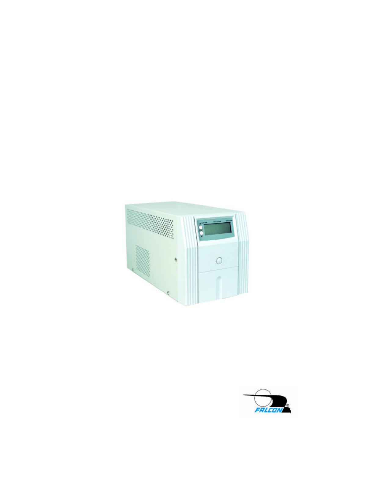
SUP SeriesTMUser’s Guide
700-1000VA
SUP700-1C, SUP1.0K-1C
OM48031-SUP, 01/09/04, Rev A.
FALCON® ELECTRIC, INC.
5106 Azusa Canyon Road
Irwindale, CA 91706
Tel. 626-962-7770
Fax. 626 962-7720
WWW.FALCONUPS.COM
800.842.6940
Page 2

TABLE OF CONTENTS
Important Safety Instructions (READ FIRST) . . 2
Chapter 1.
SUP UPS Overview . . . . 3
Chapter 2.
Installation . . . . . . 4
Inspecting the Equipment . . . . 4
UPS Setup . . . . . . . 4
Communications Interface . . . . 5
Chapter 3.
Controls, Displays & Functions . . . 6
Front Panel Diagram & Description . . . 6
LCD Symbol Descriptions . . . . 6
LCD Metering Display Modes . . . . 9
Rear Panel Diagram & Description . . . 9
Chapter 4.
Operation . . . . . . 11
Turning The UPS On and Off . . . . 11
UPS Self Test . . . . . . 11
UPS Overload Condition . . . . . 11
DC Start, Cold Start . . . . . 11
Green Mode Function . . . . . 11
Battery Charging . . . . . . 12
UPS Reset . . . . . . . 12
Remote Control . . . . . . 12:
Chapter 5.
Maintenance & Technical Support . . 13
Care & Maintenance . . . . . 13
Battery Replacement Warning . . . . 13
Battery Replacement . . . . . 13
Storing the UPS and Batteries . . . . 14
FCC Considerations . . . . . 14
Technical Support & RMA Procedure . . . 15
Requesting Technical Information or Support. . 15
FALCON Web Support . . . . . 15
Warranty . . . . . . . . 16
Specifications . . . . . . . 17
1
Page 3

IMPORTANT SAFETY INSTRUCTIONS
SAVE THESE INSTRUCTIONS
This manual contains important instructions which must be followed during the
installation, operation and maintenance of this UPS and its batteries. Please read all
instructions before operating this equipment and save this manual for future
reference.
CAUTION
All of the models presented herein are designed for installation and use in a
controlled environment free of contamination.
CAUTION
This UPS utilizes voltage that may be hazardous. Do not attempt to disassemble.
This unit contains no user replaceable parts. Refer all servicing to Falcon Electric,
Inc.
CAUTION
This UPS is not intended to be used in conjunction with life support or operating
room equipment.
CAUTION
Always unplug this UPS prior to cleaning and never apply liquid or spray detergent
on the UPS.
CAUTION
Never attempt to service batteries. High voltage exists within the unit, which could
cause electrical shock. Servicing of batteries should be performed or supervised
by personnel knowledgeable of batteries and the required precautions. Keep unauthorized personnel away from batteries. When replacing the UPS batteries, use the
same number and type of batteries.
IMPORTANT
Allow at least 24 hours, after the UPS is first installed and turned on, to fully charge
the internal battery and assure the maximum backup time is available.
DO NOT
DO NOT plug this UPS into its own output as this may damage the UPS.
DO NOT remove or unplug the input cord when the UPS is turned on. This
removes the safety ground from the UPS and the equipment connected to the UPS.
CAUTION
This UPS contains its own energy source (batteries). The output receptacles
may carry live voltage even when the UPS is not connected to an AC source.
2
Page 4

CHAPTER 1
CHAPTER 1
FALCON® SMP Series - Overview
The FALCON®SUP Series UPS has the unique ability to operate from either
120Vac domestic or 230Vac international utility power, while providing
120Vac domestic output power. The SUP does not perform frequency
conversion, however it is the ideal solution for the international traveller
requring voltage conversion.
The Line-interactive or Automatic Voltage Regulator (AVR) feature provides
output voltage regulation, while the UPS is operating from the utility power.
This keeps the connected equipment's operating voltage within reasonable
limits during abnormal utility power conditions such as brown-outs, high line
voltages and surges.
All SUP models are microprocessor controlled. A Liquid Crystal Display
(LCD) is conveniently located on the front panel. This display gives
immediate and detailed UPS and power information without having to
connect an expensive monitoring computer. An intelligent RS-232 computer
interface port is also located on the UPS rear panel in the event remote
monitoring or unattended computer shutdown is required. An optional
external SNMP/HTTP agent is available, giving the ability to manage the
UPS remotely across a LAN, WAN or via the Internet.
Unlike many other line-interactive UPSs on the market, the SUP models
produce a sinewave output voltage, just like the incoming utility power. This
assures your delicate electronic equipment will always receive the sinewave
power it was designed for.
All models have an advanced two-stage battery charger providing safe, fast
battery recharging while yielding a longer battery life.
All models have advanced surge protection circuitry to prevent damaging
power line transients from reaching your equipment. Additional surge protected, RJ11 telephone jacks are provided on the UPS rear panel.
3
Page 5

Installation
Inspecting the Equipment
UPS Setup
1. Verify that the following is included in the UPS shipping carton:
2. Verify that the UPS unit is to be used with the proper input voltage and
CHAPTER 2
CHAPTER 2
If any FALCON®equipment has been damaged during shipment, keep
the shipping cartons and packing materials for the carrier and file a
claim for shipping damage. If you discover damage after acceptance,
file a claim for concealed damage.
To file a claim for shipping damage or concealed damage: 1) File with
the carrier within 15 days of receipt of the equipment; 2) Send a copy
of the damage claim within 15 days to the Falcon®Service Department.
UPS, Software CD, Domestic 120Vac Power Cord, European style
Schuko Power Cord, Owner's Manual, UPS/Computer Cable and
Battery connection jumper plug.
the equipment to be connected to it’s output is designed to operate
from a 120Vac source. If the UPS is to be connected to a 230Vac,
50Hz European source verify the connected equipment was designed
to operate from a 120Vac, 50Hz power source. This information is
stated on the nameplate label located on the model number label
located on rear panel of the unit.
3. This UPS has been shipped with the battery connection jumper
removed to meet new transportation regulations.
IMPORTANT
THE BATTERY CONNECTION JUMPER MUST BE INSTALLED
PRIOR TO PLUGGING IN AND ATTEMPTING TO TURN ON THE
UPS.
4. Select a suitable location for the UPS, near enough to the computer or
equipment to allow connection of the equipment power plug to the
receptacles located on the rear panel of the UPS.
5. If you are connecting the UPS to a PC Computer, you may want to
install the supplied UPSilon shutdown and management software on
your computer after connection the UPS interface cable to the RS-232
interface connector located on the UPS rear panel. Then connect the
mating end of the cable to an unused serial port located on the
computer rear panel. Before the UPS will be able to communicate
properly with your computer, install the supplied computer monitoring
and shutdown software.
4
Page 6

Communications Interface
The UPS provides both a contact closure and a true RS-232 computer
interface.
The definition and setup for RS-232 is as follows:
Baud Rate : 2400 bps
Data Length : 8 bits
Stop Bit : 1 bit
Parity : None
Pin #6: RS-232 data Tx out
Pin #7: Common for Pin #6 and Pin #9
Pin #9: RS-232 data Rx In
The definition and setup for DB9 (optional) is as follows :
Pin #2: AC Power Failure
Pin #4: Common GND of Pin #2 & Pin #5
Pin #5: UPS Battery Low
Pin #6: Turn off UPS
Pin #7: GND for Pin 6
The computer interface pin-out is stated above for reference only. Use
Pin #4 as the common for Pins #2 and #5. Pins #2 and #4 are
normally closed and will open when the utility fails. Pins #5 and #4 are
normally open and will close at the low battery indication.
The UPS will shut down when a 5-12 Vdc voltage is applied across
Pins #6 and #7 for three seconds, while the UPS is on battery mode.
IMPORTANT
6. DO NOT BLOCK UPS AIR VENTS. THE UPS MUST NOT BE
INSTALLED IN AN ENCLOSED AREA.
7. If you have not already done so, connect the equipment to be
protected to the UPS output receptacles located on the rear panel.
Verify that the connected equipment does not exceed the rated output
(in watts) of the UPS.
8. Select the proper line cord and connect it to the UPS power inlet.
Plug the UPS power cord into the nearest grounded wall outlet. If the
UPS does not power up automatically, depress and hold the control
button located on the UPS front panel until the UPS turns on.
5
Page 7

CHAPTER 3
CHAPTER 3
Controls, Displays & Functions
FRONT PANEL
C
A. Main Control Button - This button is used to turn the UPS on and
off, to perform a UPS self test, or to reset and silence an audible
alarm. Refer to page 10 for operation instructions.
B
A
B. A Liquid Crystal Display (LCD) is provided. Please reference the
number designation for the display function and the function
descriptions referenced in this manual. Refer to pages 6-8 in this
manual.
C. Two LCD metering function select buttons are provided. The upper
button scrolls the display through the metering functions in an
upward direction, the lower button in a downward direction. Refer to
“LCD Metering Display Modes” referenced on page 8 of this manual.
6
Page 8

LCD SYMBOL DESCRIPTIONS
LCD DISPLAY
1. Over Load --The connected load exceeds the UPS output rating.
Remove some of the load from the UPS to correct this
condition.
2. Load Level --Bar graph indicates the percent of UPS load capacity
remaining.
3. UPS is loaded - This symbol is displayed when the UPS output load
exceeds 30 watts and disappears when the load is
under 25%.
4. Normal Mode - The sinewave symbol will be displayed when the
UPS is operating normally from the utility line.
Battery Mode - The sinewave and battery symbols will blink when
the UPS is operating on its internal battery.
Test Mode - The sinewave symbol will display steadily and the
battery symbol will blink during a UPS self test.
5. Buck Mode - The Automatic Voltage Regulator (AVR) is reducing
the UPS output voltage due to a high utility voltage
condition. The sinewave symbol is also displayed to
indicate that the UPS is operating normally from the
utility line.
7
Page 9

6 Boost Mode - The AVR is increasing the UPS output voltage due to
a low utility voltage condition or "Brown-out". The
sinewave symbol is also displayed to indicate that the
UPS is operating normally from the utility line.
7. Timer is enabled - This symbol will be displayed during the following
conditions:
a) The UPS has been programmed to automatically turn
on or off using the supplied remote monitoring software.
b) The green mode is enabled and the UPS output load is
under 25 watts. The UPS will turn off after a 30 second
delay.
8. Over Temperature - The temperature inside the UPS has exceeded
55ºC. If the end-user does not reduce the UPS
output load or correct the cause of the UPS
overheating, the temperature will continue to
rise and upon reaching 60ºC the UPS will
shutdown to prevent damage due to excessive
overheating.
9. Fan off - This symbol is used on special extended backup models
only.
10. Alarm off - The audible alarm has been silenced. To reset the alarm
during backup mode, briefly depress the control button.
11. UPS fault - Attempt to perform a UPS reset by depressing the
control button and holding it for ten seconds. If the UPS
resets and operates normally, no further action is
required. If the UPS fault indicator is still displayed, the
UPS has failed and must be repaired.
12. Battery low - When the battery charge level is low, the word "LOW"
will be displayed inside the battery normal symbol.
13. Battery normal - During normal utility operating this symbol
indicates a charged battery.
14. Battery level - When the battery is fully charged, all five bar graph
segments will be dark. As the battery discharges, the
segments will disappear starting from the top
segment and end with the bottom segment.
8
Page 10

15. LCD Metering Display - When the UPS is turned on, this portion of
Battery Fuse
Step 1C
Battery Fuses
the LCD display indicates the AC output
voltage initially. Depressing the downward
scroll button will indicate the following each
time it is depressed:
LCD Metering Display Modes
(use display scroll buttons to change modes; modes are in descending order)
Mode Value Display Description
AC Output Voltage AC Output Voltage
AC Input Voltage AC Input Voltage
AC Output Frequency (Hz) AC Output Frequency
Battery Voltage DC Battery Voltage
Temperature ºC Internal UPS Temperature
Timer Minutes to off The UPS will turn off when the displayed
value reaches zero.
Timer Hours to on The UPS will turn on when the display
reaches zero.
Battery Minutes to off The estimated remaining battery run time
while in battery backup mode.
JUMPER
TYPICAL UPS REAR PANEL
6
5
2
4
5
3
NEMA Type
4
3
2
1
JUMPER SLOT
IEC Type
1. Battery Disconnect Jumper - To install the Jumper use the
following procedure.
a) Using a #1 Phillips screwdriver remove the two screws securing
the battery disconnect cover.
b) Remove the battery disconnect jumper plug from the plastic bag.
c) Press the disconnect jumper into the socket visible through the
hole exposed after removal of the cover. A small popping sound
may occur; this is normal.
9
Page 11

2. Input Fuse - Always replace with the same fuse type and rating.
3. Inlet - for connection of incoming power cord.
4. UPS output receptacles - The top NEMA type receptacles will be
found on all domestic (120V) models.
IEC type receptacles will be found on
international (230V) models.
5. DB-9 RS-232 computer interface connector.
6. Surge protected, RJ11 type telephone jacks - To provide surge
protection for your fax, modem or other telecommunications devices.
Connect the incoming telephone line to one of the jacks. Then,
connect the fax, modem or other device to be protected to the other
jack.
7. Audible Alarms- Reference the following table.
ALARM PERIOD STATUS INDICATED
No Beep Utility Good
UPS OFF
UPS
TURNED ON
No Beep Utility Loss
No Beep
No Beep Continuously Normal (utility good)
(Can be silenced)
Beep
(Cannot be
silenced)
Beep 8 beeps per second DEFECTIVE BATTERY
LCD flashes every 2 seconds
One beep every 4 seconds
2 beeps every 4 seconds
4 beeps per second
Timer on, refer to operation section
Operating on battery mode
(no load) Beep
Operating on battery mode
Operating on battery mode
(LOW BATTERY)
#9
(loaded)
10
Page 12

Operation
1. Turning The UPS On and Off
2. UPS Self Test
3. UPS Overload Condition
CHAPTER 4
CHAPTER 4
Depending on how the UPS was turned off, it may automatically turn
on when the input plug is plugged in. If it does not turn on
automatically, depress the control button located on the front panel
for four seconds until the UPS turns on. To turn the UPS off press
and hold the control button for five seconds or until the UPS turns
off. UPS batteries will still continue to recharge after the UPS
has turned off.
Depressing the control button for one second while the UPS is
turned on will initiate a self test sequence.
To ensure that your computer equipment will be protected during a
utility failure, it is important to make sure that the maximum power
required from the equipment is not over the rated capacity of the
UPS. The LCD overload indicator will be displayed and an audible
alarm will sound if the load is over 120% of the UPS's rated
output. If the over load is greater than120% , the UPS will shut
down immediately to protect the itself. After three seconds, if the
overload is removed the UPS will automatically turn on again. If the
overload is still present the UPS will turn off and stay off, requiring
the UPS be manually restarted. Always correct any overload
condition immediately.
4. DC Start, Cold Start
To start the UPS when utility power is not available, press and hold
down the control button twice for one second each time. The UPS
will start up and run on its internal battery until discharged. If you do
not depress the control button to turn the UPS off during battery
operation, the UPS will automatically restart when utility voltage is
reapplied. The UPS batteries should not be left discharged for long
periods of time or battery damage may occur.
Always reconnect the UPS to a utility source, turn the UPS on and
allow the batteries to recharge for eight hours after the batteries
have been fully discharged due to DC operation.
5. Green Mode Function
The UPS is equipped with a Green mode function. If no load is
present at the UPS output receptacles (no equipment connected or
the load is less than 25 watts), the UPS will shut down within 12
seconds. Should the utility AC be lost during the shut down, the UPS
will automatically restart and again shut down after another two
minutes of no load being applied.
11
Page 13

6. Battery Charging
This UPS is shipped from the factory with its batteries fully charged.
However, some charge may be lost due to the self discharge
characteristics of the internal sealed lead-acid battery. Always allow
the UPS to recharge for 24 hours prior to use. To recharge, simply
connect the UPS line cord to a powered receptacle. The UPS does
not have to be turned on for batteries to recharge. During normal
use, the UPS will self recharge should the battery be depleted due to
a loss of utility power.
7 UPS Reset
In the event the UPS will not accept commands and appears to be
locked up, depress the control button for and hold for ten seconds.
The UPS CPU will be reset.
8. Remote Control
The UPS can be set for an automatic daily shutdown and start up.
This command must be set through the RS-232 interface using the
supplied software. When this function is set, a timer inside the UPS
will begin to run.
The load will be turned off according to the shutdown and start up
schedule set in the software, which is then transferred and stored in
the UPS memory. During the period of turn off to the next turn
on, the status LCD "time entered" symbol will blink.
12
Page 14

CHAPTER 5
CHAPTER 5
Maintenance & Technical Support
1. Care & Maintenance
Falcon®SUP Series UPSs are designed to be maintenance free.
They can be cleaned with a damp cloth or non-abrasive cleanser, providing the
UPS is turned off and the input plug is disconnected from the utility source.
On a regular basis, check the vents to make sure they are kept free from
accumulation of dust, dirt or lint.
2. Battery Replacement Warning
Momentarily depressing the UPS control button while the UPS is operating
normally from utility power will place the UPS into self-test. In the event the UPS
batteries are weak, an alarm will sound as an indication that the batteries need
to be replaced. For full battery life, keep the UPS close to an ambient
temperature of 77ºF. The batteries should never be exposed to temperatures
below 40ºF and above 85ºF.
3. Battery Replacement
This UPS contains sealed maintenance-free batteries (VRLA). When situated in
a typical office environment, with the proper charging and limited cycling, these
batteries can last many years. In home, office or computer room
environments, the batteries should be replaced every three to five years.
WARNING
Never attempt to service batteries. High voltage exists within the unit, which
could cause electrical shock. Servicing of batteries should be performed or
supervised by personnel knowledgeable of batteries and the required
precautions. Keep unauthorized personnel away from batteries.
When replacing the UPS batteries, use the same number and type of batteries.
NEVER
A. NEVER dispose of batteries in a fire, as batteries will explode.
B. NEVER dispose of used batteries or the UPS in the trash or landfill as it is
against federal and state laws. The UPS and Batteries must be recycled.
For UPS and battery recycling information, please contact our service
department for the name and address of the nearest battery recycling facility.
CAUTION
A. Do not open or mutilate the battery or batteries. Released electrolyte is
harmful to the skin and eyes. It may be toxic.
B. A battery can present a risk of electrical shock and high short circuit current.
REFER ALL BATTERY SERVICING OR REPLACEMENT TO A QUALIFIED
SERVICE TECHNICIAN. NEVER ATTEMPT TO REPLACE THE BATTERIES.
13
Page 15

NECESSARY PRECAUTIONS
The following precautions should be observed by a qualified technician when
working with batteries:
1. Remove watches, rings, or other metal objects.
2. Use tools with insulated handles.
3. Wear rubber gloves and boots.
4. Do not lay tools or metal parts on top of batteries
4. Storing the UPS and Batteries
Should you need to store the UPS for a long period, fully recharge the battery
just prior to storage and recharge the battery every 6 months by plugging the
UPS into a power outlet. It is recommended that the batteries charge for 24
hours after long-term storage.
5. FCC Considerations
This equipment generates and uses radio frequency energy and if not installed
and used properly in strict accordance with the manufacturer's instructions,
may cause interference to radio and television reception. All models covered in
this manual have been tested and found to comply with the limits for a Class A
computing device, in accordance with the specifications in FCC regulations,
Part 15, Subpart J, which are designed to provide reasonable protection
against such interference.
If this equipment does cause harmful interference to radio or television
reception, which can be determined by turning the equipment off and on, the
user is encouraged to try to correcting the interference by one or more of the
following measures:
a. Reorient or relocate the receiving antenna.
b. Increase the separation between the equipment and the receiver.
c. Connect the equipment into an outlet on a circuit different from that to
which the receiver is connected.
d. Consult the dealer or an experienced radio/television technician for
assistance.
14
Page 16

6. Technical Support
Your FALCON®Electric SUP Series UPS is backed by one of the finest
customer service teams assembled. Write, call, fax or email should you
require technical assistance or service.
Should service be desired, you must first obtain a Return Material Authorization
number (RMA) and return shipping instructions from our customer service
department. Please have your UPS model, serial numbers and date of
purchase on hand prior to the call. (This information is located on the
identification label on the rear panel of the unit.) The information is essential in
retrieving your unit's historical records.
FALCON ELECTRIC, INC.
5106 Azusa Canyon Road
Irwindale, CA. 91706
Voice 626.962.7770
Fax 626.962.7720
Service 800.842.6940
Email: service@falconups.com
WWW.FALCONUPS.COM
The RMA number issued must appear on the outside of the shipping carton.
The original shipping container must be used when returning any SUP Series
product. Falcon®Electric will not assume any responsibility for shipping
damage. In the event of shipping damage you will be charged for repairs due
to the damage.
All units must be returned prepaid. The address and shipping instructions will
be given to you at the time the RMA is issued.
7. Requesting Technical Information or Support.
You may request technical information or support by email or telephone.
Please send your technical or support questions by email to:
SUPPORT@FALCONUPS.COM
You may contact a FALCON support engineer directly by calling the FALCON
support line between 9:00 am and 4:00 pm PST.
626.962.7770
8. FALCON Web Support
Product data sheets, specification and owner’s guides are available in Adobe
.PDF format on our corporate website.
WWW.FALCONUPS.COM
15
Page 17

WARRANTY
WARRANTY
1. TIME AND SCOPE OF WARRANTY:
1.1 FALCON®hereby warrants parts shipped under this Agreement to be free from defective workmanship for
a period of one year following date of shipment. Accidental damage, misuse or normal wear and tear shall
not be construed as a defect.
1.2 The date of shipment as used herein will be the date on the Bill of Lading. If no Bill of Lading is issued,
the date of shipment shall be shown on seller's shipping document.
1.3 No provision of this warranty shall cover equipment which has been altered or modified from the originally
specifications manufactured unless authorized in writing.
1.4 No provision of this warranty shall cover batteries. However, battery manufacturer's warranties will be
passed through to the customer whenever applicable.
2. LIMITS OF "IN WARRANTY" SERVICE LIABILITY:
2.1 FALCON®is obligated during the in-warranty period to provide service and/or adjustments to equipment
returned to the factory at the expense of buyer (the term "factory" as used here-in shall also include any
field service centers which may be established by FALCON®) and to repair or replace any part(s) thereof
which in the opinion of authorized FALCON®personnel are found to have been defective during the
warranty period.
2.2 Equipment requiring in-warranty services must be returned to the factory with all transportation charges
prepaid, clearly tagged, stating the nature of the trouble experienced, and the disposition of the equipment
after repair. The equipment will be returned freight collect by FALCON®to the location specified via the
best and least expensive carrier available or via customer's shipping instructions.
2.3 During the in-warranty period, no service charges shall be payable by the buyer for service performed
other than for service necessitated by accident, misuse, theft, abnormal line or source voltage fluctuations,
abnormal conditions of operation, damage by the elements or damage resulting from adjustments, repairs,
modifications made by anyone other than FALCON®authorized personnel, or the buyer's failure to
reasonably maintain the equipment.
THE FOREGOING WARRANTY IS EXCLUSIVE AND IS GIVEN AND ACCEPTED IN LIEU OF ANY AND
ALL OTHER WARRANTIES, EXPRESSED OR IMPLIED, INCLUDING WITHOUT LIMITATION THE
IMPLIED WARRANTIES OF MERCHANTABILITY AND FITNESS FOR A PARTICULAR PURPOSE. THE
REMEDIES OF BUYER SHALL BE LIMITED TO THOSE PROVIDED HEREIN. IN NO EVENT WILL
SELLER BE LIABLE FOR COLLATERAL OR CONSEQUENTIAL DAMAGES. No person is authorized to
assume on behalf of FALCON®any obligation or liability in connection with the sale, warranty or service
policy of any products manufactured and/or marketed by FALCON®beyond the warranty description on
the face hereof.
3. FALCON®ELECTRIC reserves the right to make changes, additions, and/or improvements in its products
without incurring any obligation to install them on its products previously sold. This Warranty is valid for
FALCON®product as sold.
16
Page 18

SUP Series™ UPS 700VA & 1kVA
Note: The UPS will
go to Green Mode whenever the output load is under 30 watts.
Model Number SUP700-1C SUP1.0K-1C
Nominal VA
Electrical Input
Nominal AC Voltage 120V or 230V 120V or 230V
Current-Amps 7 (120V), 3.6 (230V) 10 (120V), 5.2 ( 230V)
AC Voltage Window -21% to 25%
Frequency 50/60 Hz (Auto – Tracking)
Frequency Range 47 – 63Hz
UPS is designed for use on 120V domestic or 230V international utility power with neutral, line and ground connections.
Electrical Output
Watts 490 650
Nominal AC Voltage 120V 120V
Frequency 50/60 Hz (Auto -Tracking)
On-Line Voltage Regulation ± 8%
On Battery Voltage Regulation ± 8% Typical (prior to low battery warning)
Waveform True Sinewave
Surge Protection 125 Joules MOV
Unit Protection Short Circuit, Overload & Over Temperature
Efficiency AC to AC (Typical) 97% (120Vac Input), 90% (230Vac Input)
Battery
DC Voltage 24V 24V
Type 12V, 7AH x 2
Back Up Time @ Full Load
@ 1/2 Load
Recharge Time 5 Hours to 90%
Battery times are approximate.
Transfer Time
Bypass to Inverter Black-out, 3ms / Brown -out, 0ms
Inverter to Bypass 0ms
Electrical Connections
Input 1 - 6’ Cord with 5-15P &
Output (3) 5-15R (3) 5-15R
Environmental
Operating Temperature 0º C - 40º C (32º F to 104º F)
Altitude 7,000 Feet
Humidity 10% to 95% Non – Condensing
Cooling Low Velocity Forced Air Fans
Audible Noise @ 1 meter < 45dBA
Controls and Indicators
Control One Main Control Button – UPS On/Off, Self Test, Reset & Silence Alarms
Selection Control Two LCD Metering Scroll Function Select Buttons
LCD Display
LCD Operational Symbols Overload, Load Level, UPS is Loaded, Normal Mode, Buck Mode, Boost Mode, Timer Enabled,
Audible Alarms Low Battery, Defective Battery, Low Battery, Overload, Over Temperature, AC Out of Range
Communications RS-232 Serial Port and Contact Closure Signal interface (Bundled UPSilon 2000 Software)
Mechanical
Dimensions H x W x D
Inches (mm)
Weight lb. (kg) 33.1 (15) 33.1 (15)
Agency Listing UL1778, CUL, FCC Class A
Lead Acid Maintenance-Free
1 – 6’ Cord with Schuko
AC Input Voltage, AC Output Voltage, Output Frequency, DC Battery Voltage, Internal UPS
Timer – Minutes to Shutdown, Hours to Restart, Battery – Remaining Battery Time
High Temperature, Fan Off, Alarm Off, UPS Fault, Battery Low, Battery Level
700 1000
5 Minutes
12 Minutes
Temperature,
7.9 x 7.1 x 14.2 (200 x 180 x 360)
Lead Acid Maintenance-Free
1 - 6’ Cord with 5 -15P &
1 – 6’ Cord with Schuko
12V, 9AH x 2
4.5 Minutes
11 Minutes
©2004 Falcon®Electric, Inc. All rights reserved. Falcon®and the Falcon Electric logo are registered trademarks of Falcon Electric, Inc.
All other brand names and trademarks are the property of their respective owners.
The information and specifications stated in this document are subject to change without notice. 01-07-04 MD44034-A
Falcon Electric, Inc. - 5106 Azusa Canyon Rd. - Irwindale, CA 91706 - 800.842.6940 Fax 626.962.7720
www.falconups.com - email:sales@falconups.com
17
 Loading...