

Falcon STEAKHOUSE PLUS G1518, STEAKHOUSE PLUS G1528, STEAKHOUSE PLUS G1528P, STEAKHOUSE PLUS G1518P Installation And Servicing Instructions

RZZ 254 Ref. 1
G1518 and G1528
G1518P and G1528P
STEAKHOUSE PLUS GRILLS
INSTALLATION and
SERVICING INSTRUCTIONS
These Appliances must be installed and serviced by a competent person as stipulated by the Gas
Safety (Installation & Use) Regulations.
IMPORTANT
The installer must ensure that the installation of the appliance is in conformity with these instructions and
National Regulations in force at the time of installation. Particular attention MUST be paid to -
Gas Safety (Installation & Use) Regulations
Health And Safety At Work etc. Act
Local and National Building Regulations
Fire Precautions Act
These Appliances have been CE-marked on the basis of compliance with the Gas Appliance Directive for the
Countries, Gas Types and Pressures as stated on the Data Plate.
WARNING - TO PREVENT SHOCKS, ALL APPLIANCES WHETHER
GAS OR ELECTRIC, MUST BE EARTHED
On completion of the installation, these instructions should be left with the Engineer-in-Charge for reference
during servicing. Further to this, The Users Instructions should be handed over to the User, having had a
demonstration of the operation and cleaning of the appliance.
IT IS MOST IMPORTANT THAT THESE INSTRUCTIONS BE CONSULTED BEFORE INSTALLING AND
COMMISSIONING THIS APPLIANCE. FAILURE TO COMPLY WITH THE SPECIFIED PROCEDURES MAY
RESULT IN DAMAGE OR THE NEED FOR A SERVICE CALL.
PREVENTATIVE MAINTENANCE CONTRACT
In order to obtain maximum performance from this unit we would recommend that a Maintenance Contract be
arranged with AFE SERVICELINE. Visits may then be made at agreed intervals to carry out adjustments and
repairs. A quotation will be given upon request to the contact numbers below.
Falcon Foodservice Equipment
HEAD OFFICE AND WORKS
PO Box 37, Foundry Loan, Larbert.
Stirlingshire. Scotland. FK5 4PL
SERVICE LINE CONTACT -
PHONE - 01438 363 000 FAX - 01438 369 900
Detailed recommendations are contained in
Institute of Gas Engineers published
documents :
IGE/ UP/ 1, IGE/ UP/ 2, BS6173 and BS5440
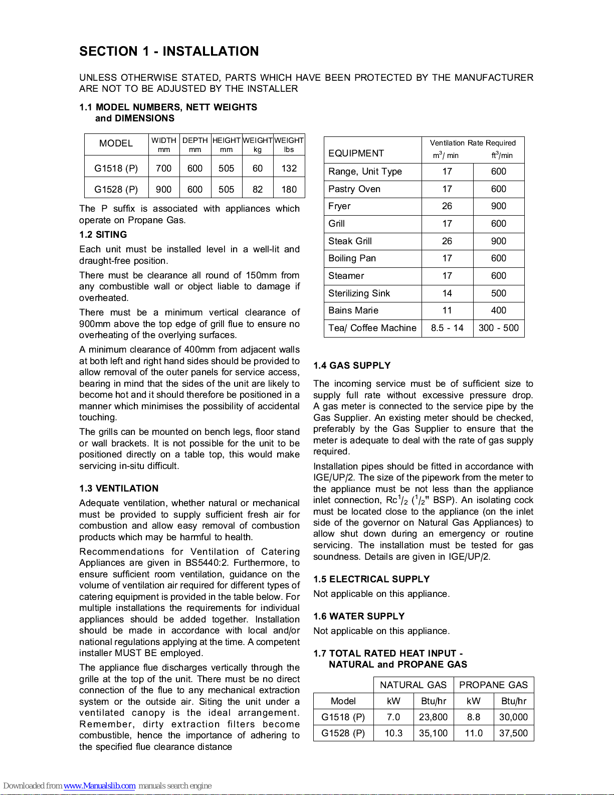
PROPANE GAS
Model kW Btu/hr
G1518 (P) 8.8 30,000
G1528 (P) 11.0 37,500
NATURAL GAS
kW Btu/hr
7.0 23,800
10.3 35,100
SECTION 1 - INSTALLATION
The P suffix is associated with appliances which
operate on Propane Gas.
1.2 SITING
Each unit must be installed level in a well-lit and
draught-free position.
There must be clearance all round of 150mm from
any combustible wall or object liable to damage if
overheated.
There must be a minimum vertical clearance of
900mm above the top edge of grill flue to ensure no
overheating of the overlying surfaces.
A minimum clearance of 400mm from adjacent walls
at both left and right hand sides should be provided to
allow removal of the outer panels for service access,
bearing in mind that the sides of the unit are likely to
become hot and it should therefore be positioned in a
manner which minimises the possibility of accidental
touching.
The grills can be mounted on bench legs, floor stand
or wall brackets. It is not possible for the unit to be
positioned directly on a table top, this would make
servicing in-situ difficult.
1.3 VENTILATION
Adequate ventilation, whether natural or mechanical
must be provided to supply sufficient fresh air for
combustion and allow easy removal of combustion
products which may be harmful to health.
Recommendations for Ventilation of Catering
Appliances are given in BS5440:2. Furthermore, to
ensure sufficient room ventilation, guidance on the
volume of ventilation air required for different types of
catering equipment is provided in the table below. For
multiple installations the requirements for individual
appliances should be added together. Installation
should be made in accordance with local and/or
national regulations applying at the time. A competent
installer MUST BE employed.
The appliance flue discharges vertically through the
grille at the top of the unit. There must be no direct
connection of the flue to any mechanical extraction
system or the outside air. Siting the unit under a
ventilated canopy i s the ideal arrangement.
Remember, dirty extraction filters become
combustible, hence the importance of adhering to
the specified flue clearance distance
1.4 GAS SUPPLY
The incoming service must be of sufficient size to
supply full rate without excessive pressure drop.
A gas meter is connected to the service pipe by the
Gas Supplier. An existing meter should be checked,
preferably by the Gas Supplier to ensure that the
meter is adequate to deal with the rate of gas supply
required.
Installation pipes should be fitted in accordance with
IGE/UP/2. The size of the pipework from the meter to
the appliance must be not less than the appliance
inlet connection, Rc
1
/2(1/2" BSP). An isolating cock
must be located close to the appliance (on the inlet
side of the governor on Natural Gas Appliances) to
allow shut down during an emergency or routine
servicing. The installation must be tested for gas
soundness. Details are given in IGE/UP/2.
1.5 ELECTRICAL SUPPLY
Not applicable on this appliance.
1.6 WATER SUPPLY
Not applicable on this appliance.
1.7 TOTAL RATED HEAT INPUT -
NATURAL and PROPANE GAS
EQUIPMENT
Ventilation Rate Required
m
3
/ min ft3/min
Range, Unit Type 17 600
Pastry Oven 17 600
Fryer 26 900
Grill 17 600
Steak Grill 26 900
Boiling Pan 17 600
Steamer 17 600
Sterilizing Sink 14 500
Bains Marie 11 400
Tea/ Coffee Machine 8.5 - 14 300 - 500
UNLESS OTHERWISE STATED, PARTS WHICH HAVE BEEN PROTECTED BY THE MANUFACTURER
ARE NOT TO BE ADJUSTED BY THE INSTALLER
MODEL
WIDTHmmDEPTHmmHEIGHTmmWEIGHTkgWEIGHT
lbs
G1518 (P) 700 600 505 60 132
G1528 (P) 900 600 505 82 180
1.1 MODEL NUMBERS, NETT WEIGHTS
and DIMENSIONS
 Loading...