

Falcon SSG1.5KRM-1, SSG1.5KRM-2, SSG2.2KRM-1, SSG2.2KRM-HW, SSG2.2KRM-2 Owner's Operating Manual
...
OWNER'S
OPERATING
MANUAL
SSG SeriesTMRackmount Industrial-Grade UPS Plus
®
Uninterruptible Power Supply Models:
SSG1.5KRM-1 - 1.5kVA, 1050W, 120Vac, -20ºC - 55ºC (-4ºF to 131ºF) Operation
SSG1.5KRM-2
- 1.5kVA, 1050W, 230Vac, -20ºC - 55ºC (-4ºF to 131ºF) Operation
SSG2.2KRM-1 2.2kVA, 1540W, 120Vac, -20ºC - 55ºC (-4ºF to 131ºF) Operation
SSG2.2KRM-HW
2.2kVA, 1540W, 120Vac, -20ºC - 40ºC (-4ºF to 104ºF) Operation
SSG2.2KRM-2 - 2.2kVA, 1540W, 230Vac, -20ºC - 55ºC (-4ºF to 131ºF) Operation
SSG3KRM-1 3kVA, 2100W, 120Vac, -20ºC - 55ºC (-4ºF to 131ºF) Operation
SSG3KRM-HW 3kVA, 2100W, 120Vac, -20ºC - 40ºC (-4ºF to 104ºF) Operation
SSG3KRM-2
- 3kVA, 2100W, 230Vac, -20ºC - 55ºC (-4ºF to 131ºF) Operation
FALCON®Electric Inc., 5116 Azusa Canyon Rd., Irwindale, California 91706, 626.962.7770, Fax 626.962.7720, Email: sales@falconups.com
2012 Falcon®Electric Inc. All rights reserved.
All other brand names and trademarks are the property of their respective owners.
The information stated in this document is subject to change without notice. 2012-24--1
Falcon®, Falcon® Electric and UPS Plus logos are registered trademarks of Falcon Electric, Inc.
SSG Rackmount Models

SSG UPS Features. ...... 3
SSG Series Double-Conversion On-line UPS Block Diagram. . . 3
Important Safety Instructions (READ FIRST) . . . 4
Chapter 1. Introduction
Manual Overview. . .... 5
Brief SSG Overview.. .... 5
Load Segment Control. ..... 5
Remote Emergency Power Off .... 5
RS-232 & USB . . . . . 5
Communications Expansion Slot. .... 5
Chapter 2. SSG UPS Circuit Descriptions
Input FIlter. ...... 6
Power Factor Correction. .... 6
DC/DC converter. . . . . . 6
DC/AC inverter .... . 6
Battery packs . . . . . 6
Battery charger. . . . . . 6
Manual bypass function. ..... 9
Automatic bypass function. ..... 9
Output fIlter ...... 9
Chapter 3. Installation
Unpacking ...... 9
Inspecting the equipment . . . . 10
Rackmount UPS setup .....10
Free standing tower installation with optional mounting feet. . 12
LCD display repositioning .....13
Battery bank installation .....13
Extended battery bank information ....14
Battery bank installation procedure . . . . 15
Chapter 4. Displays & Controls
LCD & LED indicators & icons. ....16
Function/Test button ....17
Set/Alarm Silence button .....17
How to display the UPS Parameters ....17
Chapter 5. UPS Operation
Operating Modes ......18
Normal On-line Mode ....18
Battery Mode .....18
Bypass Mode . ...19
How to turn on the UPS .....19
How to DC start the UPS .....19
How to turn off the UPS .....19
Chapter 6. UPS Setup, Configuration & Programming
How to place the UPS into setup mode. ...20
Setting the Green Mode. .....20
Setting the UPS output voltage. ....21
Setting the load segment options. ....22
Chapter 7. Communications
RS-232 & USB ......24
REPO .......25
SSG1.5KRM-1 rear panel layout ....25
SSG2.2KRM-1 & SSG3KRM-1 rear panel layout....26
SSG2.2KRM-HW & SSG3KRM-HW rear panel layout & wiring. . 27
Chapter 8. Maintenance
Storing the UPS ......28
When to replace batteries .....29
SSG1.5KRM-X Internal Battery Replacement ...29
SSG2.2KRM-X, SSG3KRM-X, SSGR & SSGR-X Battery Replacement. 30
Performing a manual battery test ....30
Recycling used battery packs . . . . 32
Chapter 9. Troubleshooting ......33
Chapter 10. Technical Support .....37
Warranty .......38
Specifications .......39-40
TABLE OF CONTENTS
2
SSG SeriesTMIndustrial-Grade UPS Features
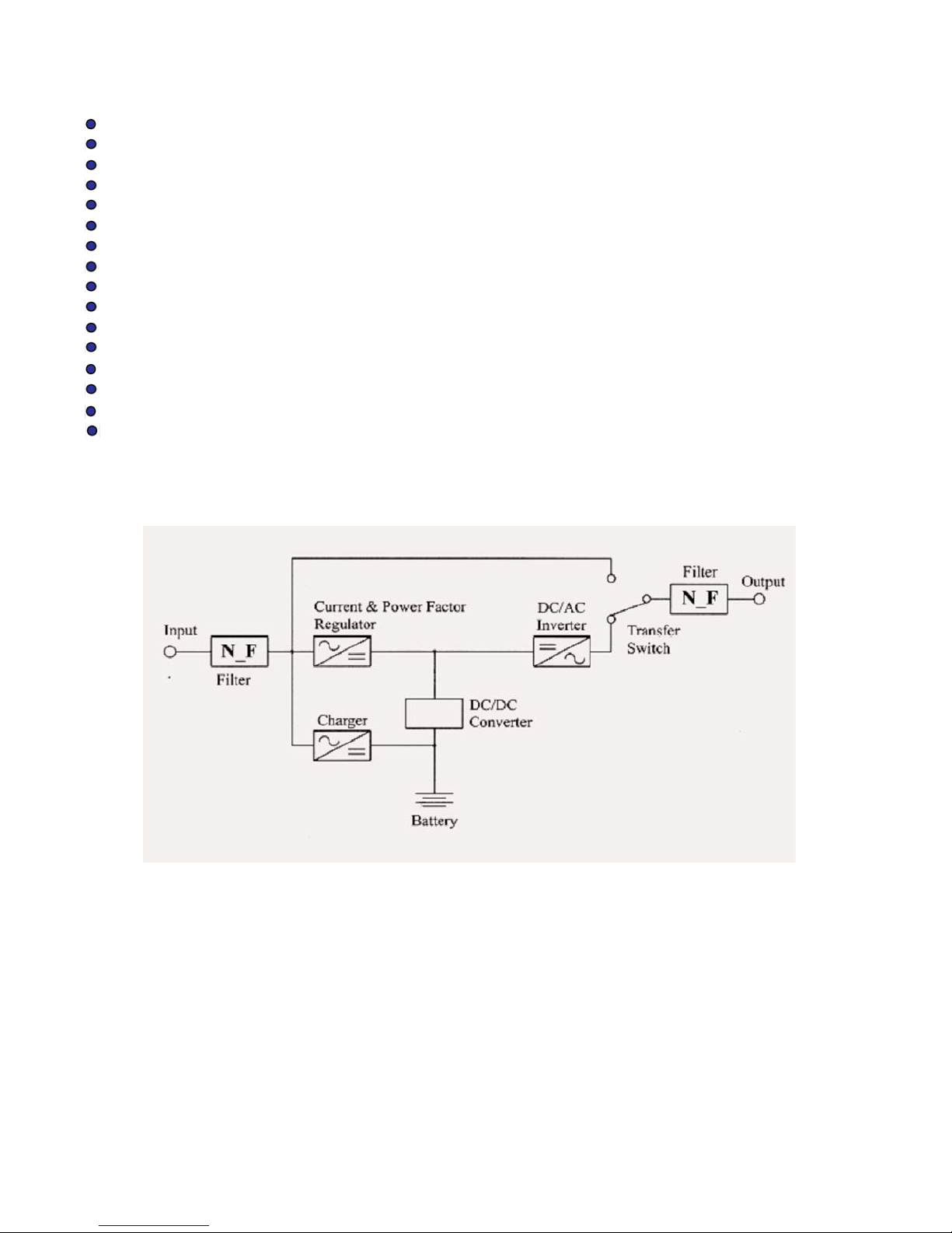
SSG Series Double-Conversion On-line UPS Block Diagram
3
True Double Conversion On-Line Sinewave Design
High Temperature 550 C Operation
LCD Display with Advanced Monitoring
Output Load Segment Control
Remote Emergency Power Off (REPO)
Input Power Factor Correction
Wide Input Voltage Window
Precision Output Voltage Regulation
Superior Brownout, Surge and Transient Protection
Optional Frequency Converter Operation
User Replaceable and Hot Swappable Battery Pack
Optional Extended Battery Banks & Chargers
RS-232C, USB & Optional SNMP/HTTP Communications
UPSILON UPS Monitoring & Management Software
RoHS Compliant
Two-Year Warranty

IMPORTANT SAFETY INSTRUCTIONS,
SAVE THESE INSTRUCTIONS
RETAIN THIS USER MANUAL!
This manual contains important instructions which must be followed during the installation, operation
and maintenance of the SSG Series UPS, battery banks, options and batteries. Please read all
instructions before operating this equipment and save this manual for future reference.
All of the models presented herein are designed for installation and use in a temperature controlled
environment, free of contamination.
This UPS operates from utility power and contains a number of high current back-up
batteries; this information is important to all personnel involved. Please read this manual first
before continuing to unpack, install or operate this UPS.
STORAGE AND TRANSPORTATION
This UPS must be handled with care and given special attention due to the high amount of energy
stored within its internal sealed, lead acid batteries. Please retain the UPS shipping container in the
event the UPS needs to be returned for service. It has been designed to ship the UPS safely,
without shipping damage.
INSTALLATION
This UPS must be installed in a clean environment, free from moisture, flammable gases or fumes
and corrosive substances. Operate the UPS in an indoor environment with an ambient temperature
range specified by model number herein.
This UPS is designed for use with industrial, scientific or data processing class equipment.
DO NOT USE TO POWER LIFE SUPPORT EQUIPMENT, OR OTHER DESIGNATED
“LIFE CRITICAL” APPLICATIONS.
The maximum UPS output load (in watts) must never exceed that shown on the UPS rating
label. NEVER CONNECT equipment that could overload the UPS or demand half-wave
rectification from the UPS, for example: electric drills, vacuum cleaners or hair dryers.
Storing magnetic media on top of the UPS may result in data loss or corruption.
WARNING
This UPS should be installed according to the instructions in this manual. Failure to do so could
result in unsafe operation and could invalidate your warranty.
WARNING
Once batteries have reached the end of their life, ensure they are disposed of properly.
PLEASE REFER TO YOUR LOCAL LAWS AND REGULATIONS FOR BATTERY RECYCLING
REQUIREMENTS. NEVER DISPOSE OF BATTERIES IN A LAND FILL.
Do not dispose of battery pack or batteries in a fire. The battery may explode. Do not open
or mutilate the battery pack. Released electrolyte is harmful to skin and eyes. It may be toxic.
CAUTION
A battery can present a risk of electrical shock and high short circuit current. The following
precautions should be observed when working on batteries:
* Remove watches, rings, and other metal objects.
* Use tools with insulated handles.
4

1.0 INTRODUCTION
Manual Overview
This user manual has been written to provide basic information about the Falcon SSG Series
Industrial Grade UPS Plus. SSG models are available in nominal power ratings of 1500, 2200 and
3000 VA . The SSG Series is a compact, rugged, double conversion, "on-line" UPS. It provides
continuous power conditioning and accepts a wide range input voltage while providing tight output
voltage regulation with a true sinewave output. The SSG Series UPS protects your sensitive
electronics equipment against the widest range of power problems, including power failures, power
sags, power surges, brownouts, line noise, high voltage spikes, frequency variations, switching
transients, and harmonic distortion.
This manual also describes unpacking, unit installation, the major features of the SSG Series UPS,
as well as detailed operation, configuration and troubleshooting.
The specifications section states all of the detailed parameters of operation for the SSG Series, and
provides general information on approvals and certifications.
Brief SSG Overview
The Falcon SSG Series Industrial-Grade UPS may be positioned vertical for desktop or floor
standing applications. Brackets are supplied to accommodate installation into a standard 19 inch
equipment rack.
The SSG Series front panel features a graphical LCD display, providing detailed operational information at a glance. The display enables the user or field service engineer to easily monitor and troubleshoot localized power problems, in addition to UPS operation. UPS control and programming is
easily accomplished using the Standby, Function/Test and Set/Alarm Silence buttons. Two levels of
audible alarms are also provided when the unit is operating on battery.
The SSG Series rear panel supports the following:
a. Load Segment Control - Multiple output receptacles are grouped into one continuous and two
programmable load segments. The two programmable load segments may be set to “shed” or turn
off the load segment at loss of utility voltage or when the low battery level has been reached. This
allows non-essential loads to be turned off, extending the amount of battery runtime.
b. Remote Emergency Power Off (REPO) - SSG models are equipped with a REPO connector that
may be interfaced with a computer room’s isolated, normally closed REPO and meets NFPA 70,
NEC645-11.
c. RS-232 and USB Ports - These ports may be used to provide communications between the UPS
and a network server or other computer systems. When used in conjunction with the supplied
UPSILON software, they give the ability to remotely monitor and control the UPS. The software will
automatically save all open computer files and initiate an unattended shutdown in the event of a loss
of utility. It supports most MS Windows and Linux operating systems. An optional Unix version is
available through Falcon at an additional cost.
d. Communications Option Board Expansion Slot - The slot supports the installation of an
optional SNMP/HTTP Agent board or contact closure interface board. The SNMP/HTTP Agent board
is a TCP-IP addressable solution to remote UPS monitoring and management via LAN, WAN or the
Internet. The agent board is supplied with client software that will remotely shutdown multiple servers
or computers through the Ethernet LAN. A CD containing software clients and a SNMP MIB II
compliant MIB is provided that supports most popular operations systems.
5

2.0 SSG UPS CIRCUIT DESCRIPTIONS
Input Filter
This portion of the circuit provides surge protection, certified to meet IEC 61000-4-5 and IEC 801-5.
It also filters out both electro-magnetic interference (EMI) and radio frequency interference (RFI) and
prevents excessive levels from being conducted back to the utility source. All SSG Series rackmount
models have been tested and comply with FCC Class B requirements.
Input Power Factor Correction
While the UPS is operating from the utility source, this circuit converts utility AC power to regulated
DC power for inverter use. It corrects the input current to maintain a sine waveform to minimize the
amount of current distortion that will be reflected back to the utility.
DC/DC Converter
The DC/DC converter utilizes energy from batteries and boosts up the DC bus voltage to a level
required by the inverter. This allows the inverter to operate continuously at optimum efficiency and
voltage. The converter incorporates a patented circuit which reduces the amount of ripple current
and EMI interference to the battery, increasing the overall battery life.
DC/AC Inverter
In utility mode operation, the inverter utilizes the regulated DC output to invert DC back into clean,
regulated sinewave AC power. When utility power fails, the inverter will receive its energy from the
battery through the DC/DC converter. In both modes of operation, the UPS inverter is on-line and
continuously generating clean, regulated AC output power to the load. The IGBT, PWM inverter is of
a very robust design and produces a pure sinewave output with a +/-2% voltage regulation. Having a
very low output impedance, it can supply the high current demands of high inrush and non-linear
loads.
Battery Packs
The SSG Series UPS utilizes a flame retardant battery pack comprised of four 12V, 7AH,
valve-regulated, sealed lead acid (VRLA) batteries in each pack. All SSG battery packs are
interchangeable between SSG 1.5kVA-3kVA models. They are easily replaced through the UPS front
panel. See replacement instructions outlined in this manual.
To maintain the optimum battery life, the user should operate the UPS in an ambient temperature of
68ºF to 77ºF (20ºC to 25ºC). Some SSG Series UPS models have batteries that may be rated operational at -20º C - 55º C (-4º F to 131º F), at these temperatures, battery life will be substantially
reduced. Optional extended battery modules are available through Falcon and will extend the
amount of battery runtime. Please refer to the exact UPS model in the attached specificaitons for the
specific battery option part number.
Battery Charger
The battery charger utilizes energy from the utility power to continuously charge the UPS batteries.
The charger operates in "constant power" mode. The UPS batteries are being charged whenever the
UPS is plugged in, turned on and operating from utility power. The internal UPS battery charger
output is rated at 1 amp.
CAUTION: When making battery bank connections to the UPS, alwasy verify the battery bank
circuit breaker(s) are in the off position. PRIOR to turning on the first battery bank circuit
breaker, ALWAYS DEPRESS AND HOLD THE BATTERY PRECHARGE PUSHBUTTON LOCATED
ON THE UPS REAR PANEL WHILE TURNING ON THE FIRST BATTERY BANK CIRCUIT
BREAKER TO PREVENT UPS DAMAGE.
6

Lithium-Ion Batteries
SSG1.5KRM-1-LI and SSG1.5KRM-2-Li models are equipped with optional internal Lithium-IonPhospate Batteries. In comparison with VRLA (valve regulated sealed lead-acid) batteries which
weigh 6 lbs. each, the Lithium-ion batteries weigh 1.8 lbs each while supplying almost twice the
battery runtime as the same model equipped with VRLA batteries.
CAUTION: If not handeled or disposed of properly Lithium-Ion batteries are extremely dangerious. Lithium-Ion-Phosphate batteries must be recycled - never dispose of the batteries in a
land-fill or trash.
Caution: Should a model SSG1.5KRM-1-LI or SSG1.5KRM-2-LI UPS require shipment by air
transporation the shipping instrucitons on the following page must be followed:
IMPORTANT SHIPPING INSTRUCTIONS
To ship by air you need to:
1) Shipper must declare Hazardous materials/dangerous Goods description and proper shipping
name – Lithium batteries, contained in equipment.
2) Identification Number – 3481(international)/3091(USA) note: that 3481 will be recognized in
the USA but the CFR still has 3091 since the US has not harmonized with the rest of the
world at this time.
3) The 12V7 batteries have been tested to UN Manual of Tests and Criteria, Part III,
subsection 38.3.
4) The 12V7 batteries are under 100Wh and are excepted from the regulations.
5) The UPS must be packed in strong outer packaging constructed of suitable material of
adequate strength and design in relation to the packaging’s capacity and its intended use.
SAVE THE ORIGINAL SHIPPING CARTON, INSERTS AND PACKING MATERIALS.
6) Each consignment with packages bearing the lithium battery handling label must be
accompanied with a document with an indication that:
• the package contains lithium ion cells or batteries;
• the package must be handled with care and that a flammability hazard exists if the
package is damaged;
• special procedures must be followed in the event the package is damaged, to
include inspection and repacking if necessary; and
• a telephone number for additional information.
11) A Shipper’s Declaration for Dangerous Goods is not required.
12) The words “Lithium ion batteries”, “not restricted” and “PI 967” must be included on the
air waybill, when an air waybill is used. The information should be shown in the “Nature and
Quantity of Goods” box of the air waybill.
IMPORTANT LITHIUM-ION BATTERY SAFETY INSTRUCTIONS
1) Always replace the external UPS battery fuse with one of the same type and rating.
2) Always replace batteries with A123 12V7 manufacturer and type. Never attempt to replace
with VRLA batteries.
3) Never dispose of the UPS or its internal batteries in a land fill. The UPS and batteries must be
recycled by a state registered recycler.
4) For emergency information concerning A123 Model 12V7 Lithium-Ion-Phosphate batteries
call: US & Canada 1-800-232-9300
International +1-703627-3887
5) Never store a UPS containing Lithium-Ion batteries in temperatures above 65oC.
6) Never attempt to replace the internal battery fuses. Batteries Must Be Replaced if internal
Battery Fuse is blown.
7

7) Never Apply a Short Circuit Across The Batteries as Personnel Injury, Fire or Explosion May
Result.
8) DANGER ---- NEVER ATTEMPT TO CONNECT AN EXTENDED BATTERY BANK
CONTAINING VRLA LEAD-ACID BATTERIES TO A UPS CONTAINING INTERNAL
LITHIUM-ION-PHOSPHATE BATTERIES.
8

Manual Bypass Function
A manual bypass button is located on the SSG front panel. When the UPS is operating from utility in
the normal on-line state, depressing this button will cause the UPS to transfer to bypass. Depressing
the bypass button again will return the UPS to the normal on-line condition.
Automatic Bypass Transfers
The SSG Series UPS will automatically switch to bypass to energize the connected load when the
UPS is first turned on, encounters an overload, encounters an over temperature condition, or upon a
UPS failure condition. Should any of these events occur, the UPS will transfer to bypass mode,
sound an audible alarm and provide a "bypass" indication on the LCD display.
Output Filter
As with the input filter stage, the output filter maintains conducted (EMC) and RFI levels below FCC
Class B limits.
3. 0 INSTALLATION
Unpacking
The SSG Series UPS may be shipped in a number of boxes, depending on the model and
configuration ordered. The number of boxes you have received should be as indicated:
MODEL BATTERY MODULE NUMBER OF BOXES
SSG1.5KRM-X n/a (internal battery pack) 1 box shipped
SSG2.2KRM-X 1 battery module 2 boxes shipped
SSG3KRM-X 1 battery module 2 boxes shipped
If you have not received the proper number of boxes, please contact Falcon Electric Customer
Service at 1-800-842-6940.
This UPS is shipped complete with all cables required for operation, including UPSILON software,
and rackmount ears for 19" rackmount shelf mounting. A full list of the box contents is provided as
follows:
SSG1.5KRM-X SSG2.2KRM-X / SSG3KRM-X
Box 1 contains: Box 1 contains:
UPS module with fitted battery pack UPS module without battery
RS-232 cable RS-232 cable
Software CD Software CD
Manual Manual
19" rack ears (+ screws) 19" rack ears (+ screws)
Box 2 contains:
Battery module
Battery connection cable
Keyhole hardware
19" rack ears (+ screws)
1 set of mounting plates & securing hardware
9

Inspecting The Equipment
Visually inspect the UPS for freight damage. If any equipment has been damaged during shipment,
keep the shipping cartons and packing materials for the carrier, and immediately file a claim for
“shipping damage” with the carrier. If you discover damage after acceptance, file a claim for
“concealed damage”.
To file a claim for shipping damage or concealed damage:
1. YOU MUST file with the carrier within 15 days of receipt of the equipment;
2. YOU MUST send a copy of the damage claim within 15 days to Falcon Electric, Inc.
CAUTION
The UPS and Battery Module are heavy. Take proper precautions when lifting or moving them.
1. Install the UPS indoors in a controlled environment.
2. Place the UPS in an area with unrestricted airflow around the unit, away from water, flammable
liquids, gases, corrosives, and conductive contaminant.
3. Maintain a minimum clearance of 4 inches in the front and rear of the UPS.
4. Maintain an ambient temperature range specified in the model specificaiton. To maximize the life
time of the batteries, an ambient temperature of 68ºF to 77ºF (20ºC to 25ºC) is recommended.
OPERATION IN TEMPERATURES ABOVE 77ºF (25ºC) WILL REDUCE BATTERY LIFE.
5. The SSG Series UPS can be installed in either a free-standing mini-tower or into a 19 inch
equipment rack. Follow the appropriate instructions in either Rackmount UPS Setup or
Free-standing UPS Installation.
Rackmount UPS Setup
All SSG Series models are shipped with front panel mounting ears that allow the unit to be installed
in a 19" equipment rack. Each UPS unit and external battery enclosure requires 2U (3.5 inches) of
vertical rack space.
NOTE !
The rack-mounting ears WILL NOT support the weight of the UPS or battery bank
by themselves. They are only to be used to secure the UPS to the front rails of the
rack. Mounting rails or an equipment shelf are required to support the weight of
each UPS or battery module.
Use the following procedure to install the UPS in an standard 19” equipment rack:
1. Place the UPS on a flat, stable surface with the front of the UPS facing you.
2. Align the mounting ears with screw holes on the side of the UPS and secure with the
supplied screws.
3. If installing the Battery Module, repeat above STEPS.
4. For slide rail installations, fasten the inner parts of the slide rails to the UPS on both
sides with the screws provided.
CAUTION: When making battery bank connections to the UPS, alwasy verify the battery bank
circuit breaker(s) are in the off position. PRIOR to turning on the first battery bank circuit
breaker, ALWAYS DEPRESS AND HOLD THE BATTERY PRECHARGE PUSHBUTTON LOCATED
ON THE UPS REAR PANEL WHILE TURNING ON THE FIRST BATTERY BANK CIRCUIT
BREAKER TO PREVENT UPS DAMAGE
10
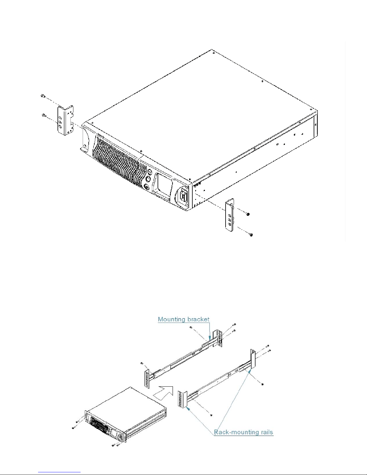
5. ** Securing hardware, slide rails and rail extensions are sold separately. Contact
Falcon Electric for these additional options and any assistance needed.**
6. Attach the two mounting brackets to the rack's mounting rails. The brackets allow
adjustment of up to eight inches of the slide assembly mounting position, front-to-back,
on the rack-mounting rails. Determine which adjustment holes to use on the bracket,
and attach it to the slide assembly on the stationary outer slide.
11
7. Install the slide assemblies, with brackets into the rack enclosure.
The return flanges on the mounting brackets and outer parts fit to the inside of the
rack-mounting rails.
8. Verify the slide assemblies are in the same alignment position on all four rack-mounting
rails. After checking alignment, TIGHTEN ALL SCREWS.
9. Insert the UPS, with inner parts attached, into the slide assemblies. You may need to
depress the locking mechanisms on the inner and outer parts of the slide assemblies
to allow the slides to retract. The UPS should move smoothly forward and backward on
the slide assemblies. If not, recheck alignment.
10. Once the UPS is installed in the rack, the load may be connected to the output of the
UPS. Ensure the equipment being connected is turned off. Plug all loads into the
output receptacles on the rear of the UPS. Plug the UPS into a dedicated wall
receptacle that is protected by a circuit breaker or fuse in accordance with national and
local electrical codes.
Use a 15 amp rated device for 1500 VA units, 20 amp for the 2200VA, and
30 amp for 3000VA. The wall receptacle must be grounded.
11. To turn on the UPS, switch on the input circuit breaker; wait for the UPS to switch from
bypass to inverter mode and then turn on the connected equipment.
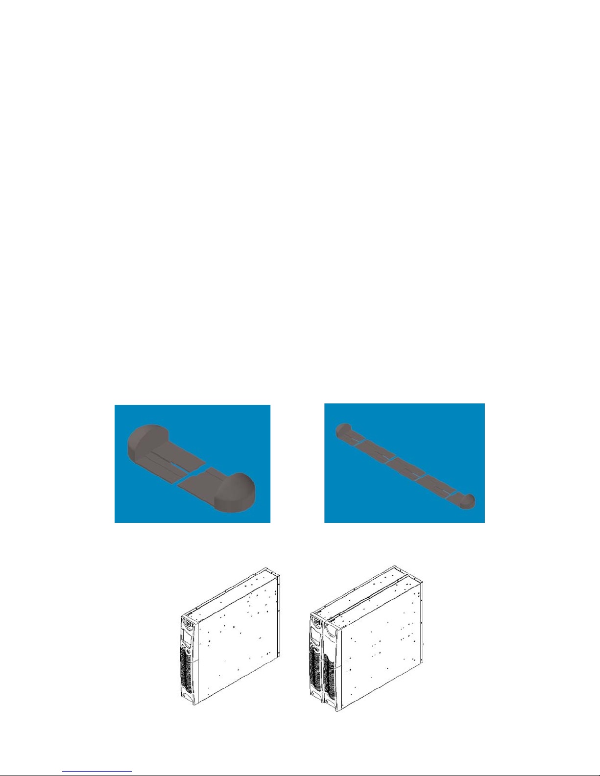
Free-standing (tower) Installation (mounting feet to be purchased seperately)
When installing the SSG Series UPS in a free-standing configuration, mounting feet for the
SSG1.5KRM-1 model may be purchased seperately to stableize the UPS
provided with mounting feet (shown below, left) to stabilize the UPS. The SSG2.2KRM-1 and
SSG3KRM-1 models are provided with keyhole hardware to "lock" the UPS and battery bank units
together. This key lock is also required if additional battery packs are added.
X
Mounting feet
Mounting feet for additional
battery banks
SSG1.5KRM-X Free Standing
SSG2.2KRM-X & SSG3KRM-X Free Standing
12
 Loading...