

Page 1
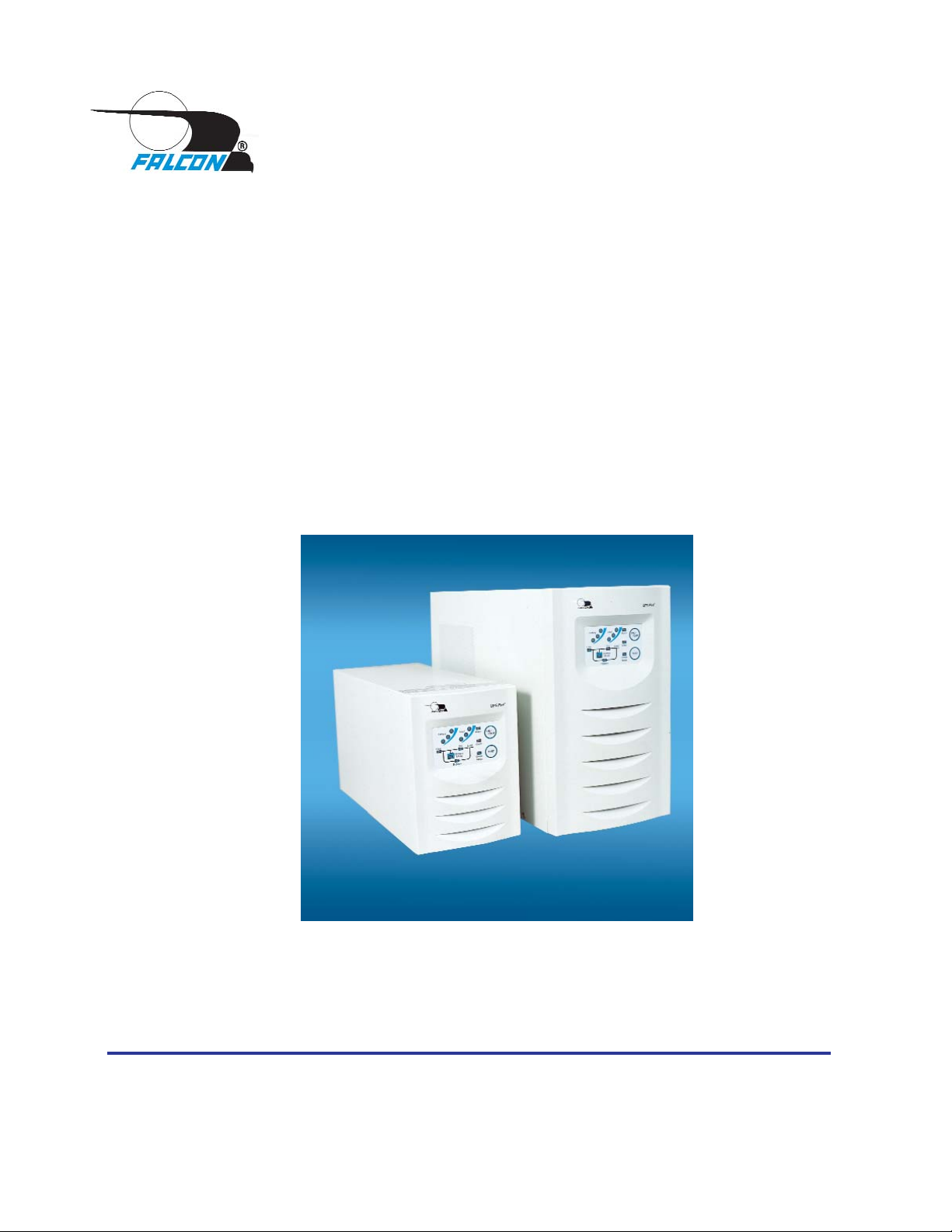
OWNER'S
OPERATING
MANUAL
Uninterruptible Power Supply Models:
SG800-1, SG800-2
SG1K-1T, SG1K-2T
SG2K-1T, SG2K-2T, SG2K-2TXI
SG3K-1T, SG3K-2T, SG3K-2TX
Detailed SG Series product specifications are available in PDF format at www.falconups.com
FALCON®Electric Inc., 5106 Azusa Canyon Rd., Irwindale, California 91706, (626) 962-7770, Fax 626-962-7720, Email: [email protected]
2003 Falcon®Electric Inc. All rights reserved.
All other brand names and trademarks are the property of their respective owners.
The information stated in this document is subject to change without notice. 2005-02-07
Falcon
®
, Falcon® Electric and UPS Plus logos are registered trademarks of Falcon Electric Inc
OM48021-1-3K Rev. F
Page 2

SG UPS Features. ...... 1
SG Series Online UPS Block Diagram. .... 1
Important Safety Instructions (READ FIRST) .... 2
Chapter 1.
SG Series UPS Overview ..... 3
True Regenerative Online Design .... 3
Input Power Factor Correction .... 3
Microprocessor Control ..... 3
SNMP/HTTP Remote Management .... 3
Extended Battery Bank Option .... 3
Frequency Converter Option ..... 3
Chapter 2.
Installation Instructions ..... 4
Dip Switch Settings DIagrams .... 6
Extended Battery Bank Interconnection . . . 7
Extended Battery Bank Installation Procedure . . 8
Extended Battery Bank Selection Guide . . . 8
Chapter 3.
Operation ....... 9
Front Panel Indicators & Function Key Diagram . . 9
Front Panel Function Description .... 9
Audible Alarms ......11
Category One Alarms .....11
Category Two Alarms .....11
Chapter 4.
Rear Panel Details ......12
SG800-1T & SG1K-1T Rear Panel ...12
SG800-2T & SG1K-2T Rear Panel ...12
SG1.5K-1T, SG2K-1T & SG3K-1T Rear Panel . . 13
SG1.5K-2T, SG2K-2T & SG3K-2T Rear Panel . . 13
SG2K-2TXI & SG3K-2TX Rear Panel ...14
Chapter 5.
Communications Interfaces. ....15
RS-232 Interface (DB-9) .....15
Communications Option Slot .....15
Contact Closure & Opto Interface Options ...16
Chapter 6.
Maintenance & Technical Support ....19
Care & Maintenance ......19
Battery Life vs. Temperature .....19
Battery Replacement ......19
Storing the UPS and Batteries.....20
FCC Considerations ......20
Technical Support & RMA Procedure ....21
Requesting Technical Information or Support. . . 21
FALCON Web Support......21
Warranty ........22
Specifications ........23
SG800VA - SG1.5KVA ......23
SG2KVA - SG3KVA ......24
TABLE OF CONTENTS
Page 3
SG SERIES UPS FEATURES
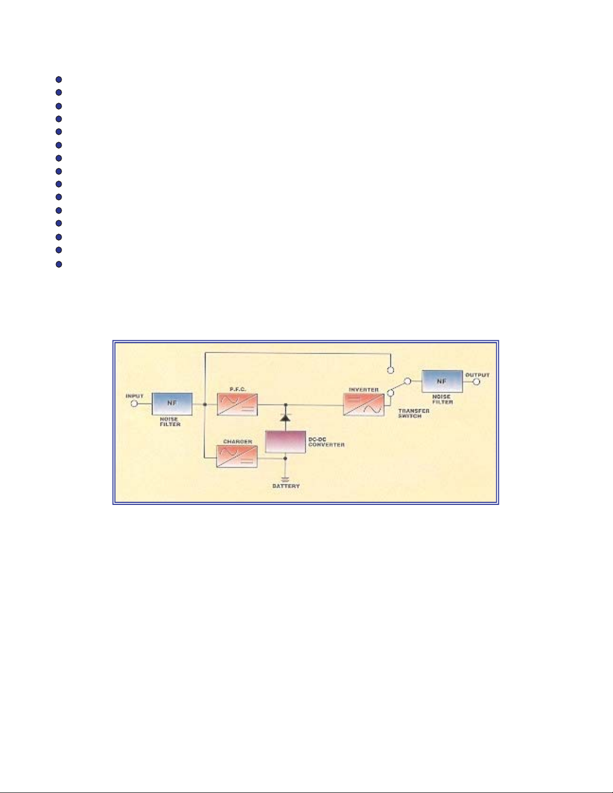
SG SERIES ON-LINE UPS SYSTEM BLOCK DIAGRAM
True Double Conversion On-Line Design
Input Power Factor Correction
Wide Input Voltage Window
Pure Sinewave Output
Precision Output Voltage Regulation
Superior Brownout, Surge and Transient Protection
Internal System Bypass
Eliminates Generator Frequency & Voltage Drift
Microprocessor Control & RS-232 Communications
UPSILON
®
Monitoring & Shutdown Software
Optional Frequency Conversion
Optional Extended Battery Packs & Chargers
Optional External Maintenance Bypass Switch
Optional Internal SNMP/HTTP Interface Card
Two-Year Warranty
1
Page 4

IMPORTANT SAFETY INSTRUCTIONS
SAVE THESE INSTRUCTIONS
This manual contains important instructions which must be followed during the installation,
operation and maintenance of this UPS and its batteries. Please read all instructions before
operating this equipment and save this manual for future reference.
All of the models presented herein are designed for installation and use in a
temperature controlled environment, free of contamination.
This UPS utilizes voltage that may be hazardous. Do not attempt to disassemble.
This unit contains no user replaceable parts. Refer all servicing to Falcon
Electric, Inc.
THIS UPS IS NOT INTENDED TO BE USED IN CONJUNCTION WITH LIFE SUPPORT OR OPERATING ROOM EQUIPMENT.
Always unplug this UPS and remove the UPS battery fuse prior to cleaning and
never apply liquid or spray detergent on the UPS.
Never attempt to service batteries. High voltage exists within the unit, which
could cause electrical shock. Servicing of batteries should be performed or supervised by personnel knowledgeable of batteries and the required precautions. Keep
unauthorized personnel away from batteries. When replacing the UPS batteries,
use the same number and type of batteries.
Allow at least 24 hours, after the UPS is first installed and turned on, to fully charge
the internal battery and assure the maximum backup time is available.
DO NOT plug this UPS into its own output as this may damage the UPS.
DO NOT remove or unplug the input cord when the UPS is turned on. This
removes the safety ground from the UPS and the equipment connected to the UPS.
This UPS contains its own energy source (batteries). The output receptacles
may carry live voltage even when the UPS is not connected to an AC source.
Should any SG Series UPS units be stored for more than two weeks, it is
mandatory that the battery fuse be removed prior to storage or battery
damage will result.
CAUTION
CAUTION
CAUTION
CAUTION
CAUTION
IMPORTANT
DO NOT
CAUTION
CAUTION
IMPORTANT
2
Page 5

CHAPTER
CHAPTER11
SG Series UPS - Overview
True Regenerative On-Line Design
As new and innovative technologies have become the backbone of today's businesses, maximum system availability is critical and downtime is more expensive than ever. Increasingly, businesses need a UPS that not only protects against blackouts, but also virtually eliminates more
frequent and subtle power disturbances. Surges, sags, line noise and brownouts can disrupt
proper operation of sensitive equipment. These disturbances may also create unnecessary production, service, and data recovery costs.
A True Regenerative On-Line UPS provides the highest level of protection against the widest
spectrum of power problems. The incoming AC utility source is converted to a regulated DC
voltage. From this DC voltage, a new AC voltage is regenerated, providing continuous, clean,
tightly regulated power to your equipment. Line-interactive and Off-line designs leave your equipment connected directly to dirty utility power. They only provide minimal transient, voltage and
backup protection. If your equipment operation is "Mission Critical", a true double conversion
On-Line UPS, such as Falcon
®
Electric's SG SeriesTMUPS Plus®, is the only clear choice.
Input Power Factor Correction
All SG Series UPS Plus models include state-of-the-art Input Power Factor Correction. This
greatly reduces the amount of current demanded from your building wiring system, yielding a
highly efficient, "building friendly" UPS.
Microprocessor Control
Falcon Electric's SG Series UPS incorporates advanced microprocessor technology. This technology makes possible a high level of internal UPS control and management. With the supplied
UPSILON
®
software, all SG Series UPS models support unattended shutdown, management,
data logging, and self-diagnostics. The software supports MS Windows
®
95, 98, NT, 2000, 2000
Server, ME, XP, Novell Netware®5 & 6, LINUX and FreeBSD. UPSILON for UNIX supports most
popular UNIX platforms and OS versions.
SNMP/HTTP Remote Management Support
Our SNMP/HTTP Agent board provides remote management and monitoring over any Ethernet
LAN, WAN or the Internet utilizing a 10BaseT-type connection. The optional SNMP/HTTP agent
installs via an option slot located behind a cover plate on the back panel of every SG Series
model.
Extended Battery Bank Option
All SG Series models have a continuous duty inverter and support the addition of optional external battery/charger packs. Whether your application requires a few additional minutes or hours,
the SG Series will be ready. Falcon also offers optional battery charger upgrades for faster
recharging. Please specify your extended battery and charger requirements at the time of your
initial order.
Frequency Converter Option
With a factory modification at the time of order, any SG Series model can be configured for use
as an international frequency converter. This makes the SG Series UPS Plus an ideal choice for
worldwide power applications. Without this modification, all SG series models will detect the
incoming utility line frequency and automatically set its output frequency to match.
3
Page 6

CHAPTER
CHAPTER22
INSTALLATION INSTRUCTIONS
1. Verify the following is included in the UPS shipping carton:
(1) UPS, (1) Software Diskette(s) & Manual, (1) Power Cord (800VA-1KVA models only),
(1) Owners Manual & (1) UPS/Computer Cable.
2. Verify the UPS unit is configured for the proper input/output voltage and frequency. This
information is stated on the nameplate label located on the rear or the side panel of the
unit. If any special input plug and output receptacle configurations were specified at the
time of order, verify for proper configuration.
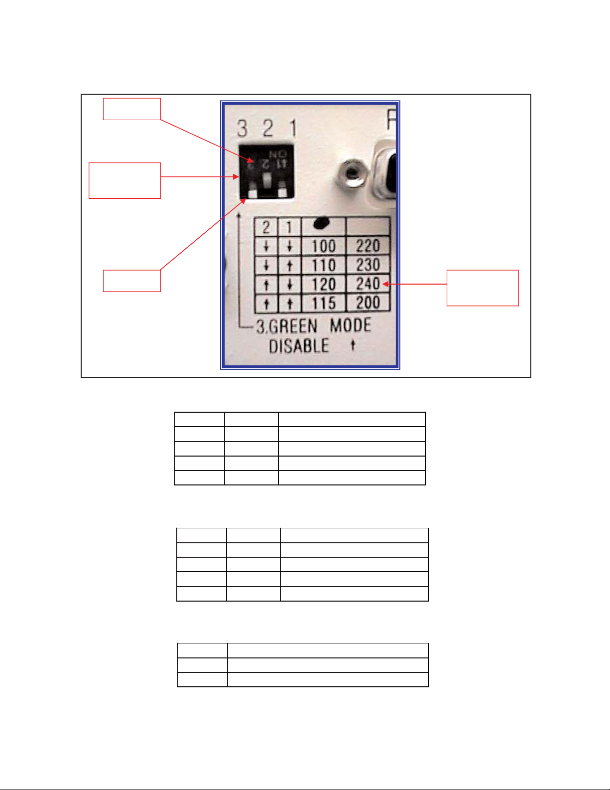
3. Set the Dip switches located on the UPS rear panel for the nominal UPS output
voltage desired. See the dip switch setting tables located on page 6.
In most cases the nominal UPS output voltage should be set to match the incoming utility
voltage. This will assure a close matching voltage in the event the UPS is placed on
bypass. NOTE: Disregard the "ON" marking on the side of the actual dip switch
housing; use the tables in this manual or the silkscreen on the UPS rear panel only.
Dip switch 3 "enables" or "disables” the "Green Mode" function. The UPS is shipped
from the factory with the switch set in the "disabled" position (up). If SW3 is switched
down or to the "enabled" position, the Green Mode function is activated. When the
load connected to the output of the UPS drops to under 10% of the full rated UPS output
for 30 seconds, the UPS is automatically placed into bypass and the inverter is turned off.
NO BATTERY BACKUP IS PROVIDED AFTER THE GREEN MODE HAS ACTIVATED.
Dip switch settings must be made while the UPS is turned off. Any changes made while
the UPS is turned on will not take effect until the UPS is turn off and back on again since
the switch settings are read by the microprocessor only during initial UPS power up
.
4. To prevent accelerated battery discharge during shipment, the 1-3Kva models have had
the battery fuse removed. INSTALL THE BATTERY FUSE PRIOR TO TURNING ON THE
UPS INPUT CIRCUIT BREAKER OR PLUGGING IN THE UPS. Apopping sound may be
heard, which is normal.
NEVER REMOVE THE BATTERY FUSE OR TURN THE BATTERY CIRCUIT BREAKER
OFF WHILE THE UPS AC CIRCUIT BREAKER IS TURNED ON AND OPERATING
FROM THE UTILITY VOLTAGE OR UPS DAMAGE WILL RESULT. UPS MUST BE
COMPLETELY SHUT DOWN PRIOR TO DISABLING THE INTERNAL BATTERY
SUPPLY.
In the event this UPS is to be turned off or stored for more than two weeks, the battery
fuse must be removed to prevent battery discharge. If placed in long-term storage, every
four months the UPS must be plugged in and turned on for 24 hours to allow the batteries
to recharge and prevent battery damage. Failure to follow these procedures will invalidate
your warranty.
CAUTION
CAUTION
4
Page 7

5. For SG800 - SG1K models, connect the power cord to the UPS inlet located on the
UPS rear panel. On SG1.5K - SG3K models the line cord is permanently attached to
the UPS.
6. Select a suitable location for the UPS near enough to the computer or equipment to
to be protected. Connect the power cord(s) for the equipment to be protected to the
UPS output receptacles.
VERIFY THE TABLE OR SURFACE SUPPORTING THE UPS WILL SUPPORT THE
WEIGHT OF THE UPS AND ANY OPTIONAL EXTENDED BATTERY BANKS.
800VA-1KVA UPS MODELS = 33 lbs. (14.9 kg)
1.5KVA- 2KVA UPS MODELS = 68.4 lbs. (31 kg)
3KVA UPS MODELS = 81.4 lbs. (37 kg)
MINI-TOWER EXTENDED BATTERY BANKS = 123 lbs. (55.8 kg) MAX. (EACH BANK)
FLOOR STANDING EXTENDED BATTERY BANKS = 363 lbs. (165 kg) MAX. (EACH BANK)
7. If extended battery banks are to be connected to the UPS, please refer to page 8 for
further instructions.
8. If unattended computer shutdown and monitoring are desired, connect the green
UPS/Computer cable to the DB-9 connector located on the UPS rear panel. Then
install the shutdown and monitoring software provided with the UPS. For your
reference, UNIX shutdown and monitoring software is available from Falcon Electric
at an additional cost.
9. Verify the location selected has adequate ventilation to allow for the proper cooling of
the UPS.
DO NOT BLOCK UPS FANS OR AIR VENTS. THE UPS MUST NOT BE
INSTALLED IN AN ENCLOSED AREA.
11. Plug the UPS power cord into the nearest grounded wall outlet. SG1K-2T 208-240V
models will automatically turn on Since they do not have an input circuit
breaker. For all other SG models, go to step 12.
12. Turn the input circuit breaker located on the UPS rear panel to the “on” position. The
internal UPS fan and front panel "line" indicator should turn on, followed by the
"bypass" LED, and after several seconds, the "inverter" LED.
13. Turn on the connected equipment and verify the UPS does not go into overload by
observing the front panel load indicator LEDs.
14. The UPS, optional external battery bank(s) and additional chargers should be plugged
in and turned on for 24 hours to charge the batteries. During this initial 24 hour
charging period, battery backup time may be substantially reduced.
TO TURN OFF THE UPS, SWITCH OFF THE INPUT CIRCUIT BREAKER
LOCATED ON THE UPS REAR PANEL AND PRESS THE ON/OFF
BUTTON LOCATED ON THE UPS FRONT PANEL UNTIL THE UPS BEEPS.
THE UPS WILL RUN FOR ABOUT 30 SECONDS AND SHUTDOWN. DO NOT
PRESS THE ON/OFF BUTTON OR TURN THE CIRCUIT BREAKER ON AGAIN
DURING THE SHUTDOWN PROCESS OR THE UPS WILL GO TO AN ALARM
CONDITION, WARNING THAT THE UPS WAS NOT SHUTDOWN PROPERLY.
SHOULD THIS OCCUR, TURN OFF THE INPUT CIRCUIT BREAKER AGAIN AND
WAIT UNTIL THE UPS SHUTS DOWN.
IMPORTANT
5
Page 8
DIP
SWITCHES
SELECTION
TABLE
ON = 1
OFF = 0
SW2
SW1
VOLTAGE
Down
Down
100V
Down
Up
110V
Up
Down
120V (Factory default)
Up
Up
115V
SW2
SW1
VOLTAGE
Down
Down
220V
Down
Up
230V (Factory Default)
Up
Down
240V
Up
Up
200V
SW3
FUNCTION
Down
GREEN MODE ON
Up
GREEN MODE OFF
SWITCH SETTINGS FOR -1 MODELS
SWITCH SETTINGS FOR -2 MODELS
GREEN MODE SWITCH SETTINGS FOR ALL MODELS
VIEW OF DIP SWITCHES LOCATED ON THE UPS REAR PANEL
6
Page 9
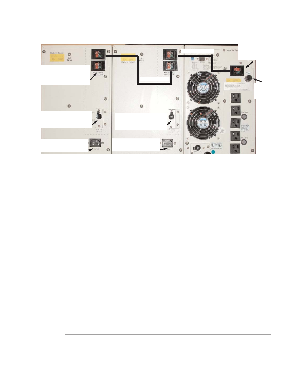
TYPICAL EXTENDED BATTERY BANK & UPS INTERCONNECTION
(Mini-tower models shown; same applies for floor standing banks)
INSTALLATION PROCEDURE FOR EXTENDED BATTERY BANKS
1. Remove the battery fuse located on the UPS rear panel. See illustration above.
2. Locate the battery interconnect cable(s).
3. Connect one end of the battery interconnect cable to the the UPS battery
connector. Connect the other end of the cable to the top battery connector on the first
battery bank. See illustration above.
4. If a second battery bank is to be connected, connect one end of the second battery
interconnect cable to the bottom battery connector on the first battery bank and
connect the other end of the cable to the top battery connector of the second battery
bank. (See illustration above.)
5. Follow the instructions in the proceeding step for additional battery banks.
6. Reinstall the battery fuse. A popping sound may be heard when inserting the fuse.
This is normal as the battery banks are pre-sharing the UPS.
7. For all battery banks that have the battery charger option installed from the factory,
perform the following:
a. Verify the battery charger circuit breaker is in the off (down) position.
b. On the battery bank nameplate label located on the rear panel, verify the
battery charger input voltage matches your utility source (120Vac or
230Vac).
c. Connect the input line cord(s) to the battery bank(s) power inlet.
d. Plug the other end of the power cord into a utility receptacle.
e. Turn on the battery charger circuit breaker(s) (up).
f. The batteries in the external battery banks are now being charged.
NOTE: Internal battery bank chargers do not charge the batteries inside the UPS.
NOTE: When the battery banks and UPS need placed shutdown for more than
two weeks, turn off the battery charger circuit breaker, disconnect the
interconnecting cables and remove the battery fuse from the UPS battery or
damage may occur.
8. RETURN
TO PAGE 5, Paragraph 8 FOR FURTHER INSTALLATION INSTRUCTIONS.
2ND BATTERY BANK
1ST BATTERY BANK
UPS
1ST CABLE
2ND CABLE
TO ADD MORE BANKS,
DAISY CHAIN TO NEXT
BANK FROM THIS
OPTIONAL BATTERY
CHARGER CIRCUIT
BREAKER
OPTIONAL BATTERY
CHARGER CIRCUIT
BREAKER
POWER INLET FOR
OPTIONAL CHARGER
POWER INLET FOR
OPTIONAL CHARGER
7
UPS
BATTERY
FUSE
TYPICAL
BATTERY
CONNECTOR
Page 10

BATTERY OPTION
MODELS
W/O Charger
SGB2S7-1K3
SGB4S7-1K3
SGB5S7-1K3
SGB10S7-1K6
SGB10S7-1K6
BATTERIES
6 Pieces 12V, 7AH
12 Pieces 12V, 7AH
15 Pieces 12V,
7AH
30 Pieces 12V, 7AH
60 Pieces 12V,
7AH
BATTERIES IN UPS
3 each of 12V, 7AH
# of CASES
Inches
(mm)
1 Mini-Tower
13.8 x 7.6 x 18.9
(350 x 193 x 480)
1 Mini-Tower
13.8 x 7.6 x18.9
(350 x 193 x 480)
1 Mini-Tower
13.8 x 7.6 x18.9
(350 x 193 x 480)
1 Floor Standing
32.1 x 10.2 x 21.8
(814 x 259 x 554)
2 Floor Standing
32.1 x 10.2 x 21.8
(814 x 259 x 554)
RUN TIME @ 100W
215 Min.
390 Min.
480 Min.
960 Min.
2000 Min.
RUN TIME @ 200W
107 Min.
210 Min.
255 Min.
520 Min.
1070 Min.
RUN TIME @ 400W
49Min.
96 Min.
120 Min.
255 Min.
550 Min.
RUN TIME @ 700W
23Min.
50 Min.
80 Min.
140 Min.
260 Min.
CHARGER OPTION INFORMATION
BATTERY OPTION
MODELS
With 120Vac Charger
SGB2S7-1K3-1
SGB4S7-1K3-1
SGB5S7-1K3-1
SGB10S7-1K6-1
SGB10S7-1K6-1
BATTERY OPTION
MODELS
With 200-240Vac
Charger
SGB2S7-1K3-2
SGB4S7-1K3-2
SGB5S7-1K3-2
SGB10S7-1K6-2
SGB10S7-1K6-2
CHARGER OUTPUT
41.1Vdc @ 4.5A
41.1Vdc @ 4.5A
41.1Vdc @ 4.5A
41.1Vdc @ 4.5A
41.1Vdc @ 4.5A
# OF CHARGERS
1 1 1 2 4
SG 1-3kVA TOWER EXTENDED BATTERY BANK SELECTION GUIDE
FOR 800VA-1KVA MODELS
BATTERY OPTION
MODELS
W/O Charger
SGB2S7-2K3
SGB2S7-2K3
SGB5S7-2K6
SGB2S7-2K3
SGB5S7-2K6
SGB5S7-2K6
BATTERIES
12 Pieces of 12V,
7AH
24 Pieces of 12V,
7AH
30 Pieces of 12V,
7AH
36 Pieces of 12V,
7AH
60 Pieces of 12V,
7AH
90 Pieces of 12V,
7AH
BATTERIES IN UPS
6 each of 12V, 7AH
# of CASES
Inches
(mm)
1 Mini-Tower
13.8 x 7.6 x 18.9
(350 x 193 x 480)
2 Mini-Towers
13.8 x 7.6 x 18.9
(350 x 193 x 480)
1 Floor Standing
32.1 x 10.2 x 21.8
(814 x 193 x 554)
3 Mini-Towers
13.8 x 7.6 x 18.9
(350 x 193 x 480)
2 Floor Standing
32.1 x 10.2 x 21.8
(814 x 193 x 554)
3 Floor Standing
32.1 x 10.2 x 21.8
(814 x 193 x 554)
RUN TIME @ 300W
170 Min.
310 Min.
390 Min.
470 Min.
760 Min.
1200 Min.
RUN TIME @ 500W
95 Min.
180 Min.
225 Min.
260 Min.
465 Min.
690 Min.
RUN TIME @ 700W
63 Min.
120 Min.
155 Min.
185 Min.
320 Min.
490 Min.
RUN TIME @ 1000W
39 Min.
79 Min.
100 Min.
120 Min.
215 Min.
330 Min.
RUN TIME @ 1400W
24 Min.
51 Min.
64 Min.
80 Min.
140 Min.
225 Min.
CHARGER OPTION INFORMATION
BATTERY OPTION
MODELS
With 120Vac
Charger
SGB2S7-2K3-1
SGB2S7-2K3-1
SGB5S7-2K6-1
SGB2S7-2K3-1
SGB5S7-2K6-1
SGB5S7-2K6-1
BATTERY OPTION
MODELS
With 208-240Vac
Charger
SGB2S7-2K3-2
SGB2S7-2K3-2
SGB5S7-2K6-2
SGB2S7-2K3-2
SGB5S7-2K6-2
SGB5S7-2K6-2
CHARGER OUTPUT
82.5Vdc @ 4A
82.5Vdc @ 4A
82.5Vdc @ 4A
82.5Vdc @ 4A
82.5Vdc @ 4A
82.5Vdc @ 4A
#. OF CHARGERS
1 1 1 1 2
3
FOR 1.5KVA-2KVA MODELS
BATTERY OPTION
MODELS
W/O Charger
SGB2S7-3K3
SGB2S7-3K3
SGB5S7-3K6
SGB2S7-3K3
SGB5S7-3K6
SGB5S7-3K6
BATTERIES
16 Pieces 12V,7AH
32 Pieces 12V, 7AH
40 Pieces 12V, 7AH
48 Pieces 12V, 7AH
80 Pieces 12V, 7AH
160 Pieces 12V, 7AH
BATTERIES IN UPS
8 each of 12V, 7AH
# of CASES
H x W x D
Inches
(mm)
1 Mini-Tower
13.8 x 7.6 x 18.9
(350 x 193 x 480)
2 mini-Towers
13.8 x 7.6 x 18.9
(350 x 193 x 480)
1 Floor Standing
32.1 x 10.2 x 21.8
(814 x 259 x 554)
3 Mini-Towers
13.8 x 7.6 x 18.9
(350 x 193 x 480)
2 Floor Standing
32.1 x 10.2 x 21.8
(814 x 259 x 554)
4 Floor Standing
32.1 x 10.2 x 21.8
(814 x 259 x 554)
RUN TIME @ 500W
135 Min.
260 Min.
310 Min.
380 Min.
640 Min.
1350 Min.
RUN TIME @ 1000W
59 Min.
115 Min.
140 Min.
170 Min.
300 Min.
620 Min.
RUN TIME @ 1500W
33 Min.
68 Min.
84 Min.
105 Min.
190 Min.
400 Min.
RUN TIME @ 2100W
20.5 Min.
43 Min.
57 Min.
69 Min.
125 Min.
270 Min.
CHARGER OPTION INFORMATION
BATTERY OPTION
MODELS
With 120Vac Charger
SGB2S7-3K3-1
SGB2S7-3K3-1
SGB5S7-3K6-1
SGB2S7-3K3-1
SGB5S7-3K6-1
SGB5S7-3K6-1
BATTERY OPTION
MODELS
With 208-240Vac
Charger
SGB2S7-3K3-2
SGB2S7-3K3-2
SGB5S7-3K6-2
SGB2S7-3K3-2
SGB5S7-3K6-2
SGB5S7-3K6-2
CHARGER OUTPUT
110Vdc @4.5A
110Vdc @4.5A
110Vdc @4.5A
110Vdc @4.5A
110Vdc @4.5A
110Vdc @4.5A
# OF CHARGERS
1 1 1 1 2
4
FOR 2.5KVA-3KVA MODELS
8
NOTE: The backup times stated are for reference only. Backup time may vary due to the type of load, battery age or condition,
environmental conditions, etc.
Page 11
9
CHAPTER
CHAPTER33
OPERATION
1
2
3
4
5 6 7
8
9
10
11
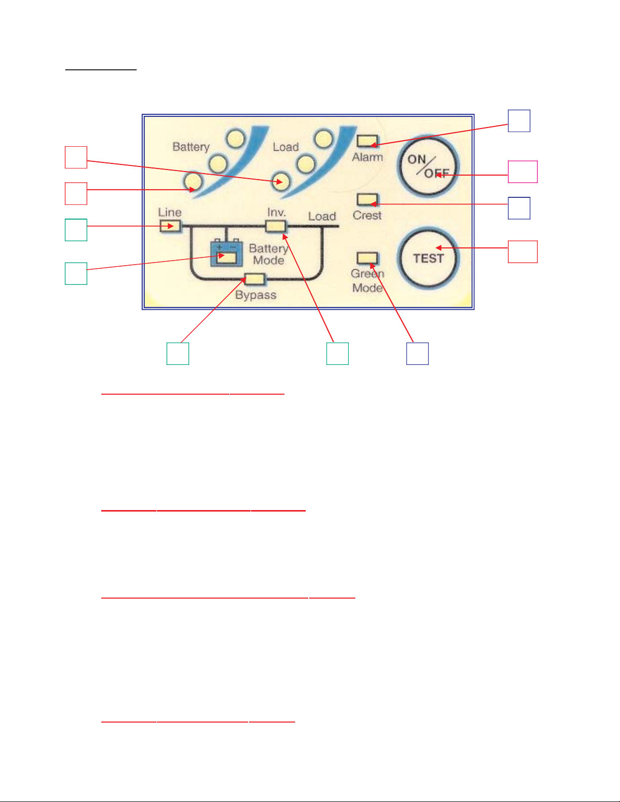
UPS FRONT PANEL INDICATOR AND FUNCTION KEYS
1. LOAD LEVEL
INDICA
TOR LEDS
*The first or bottom LED is lit when the output load is greater than 25% of the rated
output of the UPS.
*The second LED is lit when the output load is greater than 50% of the rated output
of the UPS.
*The third LED is lit when the output load is greater than 75% of the rated output of
the UPS.
2. BA
TTERY LEVEL INDICATOR LEDS
*The third or top LED is lit when the battery is fully charged.
*The Second LED is let when the battery level is above the low battery warning
Level.
*The first LED is lit when the battery level is above the battery cutoff voltage.
3. LINE / SITE WIRING F
AULT INDICATOR LED
For models configured for standard 120 volt domestic usage, this LED is lit to a
steady on state when Utility voltage is present. However, should the LED flash on
and off, it is an indication that the HOT and NEUTRAL wires are reversed some
where in the building wiring. Typically at the wall outlet.
It is normal for this LED to flash with 208 and 240 volt domestic models as these
voltages are normally LINE to LINE, without a neutral.
4. BA
TTERY MODE INDICATOR LED
This LED is lit when the unit is operating from battery.
Page 12

5. BYPASS INDICATOR LED
When this LED is lit the UPS bypass is active. Should the Alarm LED be lit at the
same time, the UPS detected an internal failure and the UPS must be serviced.
6. INVERTER INDICATOR LED
When this LED is lit, the UPS inverter is operating and powering the connected load.
7. GREEN MODE LED INDICA
TOR
This LED is lit when the connected output load of the UPS drops to under 10% of
the full rated output of the UPS, providing SW3 is in the "down" position (Green
Mode Enabled) as shown on page 7. The UPS is automatically set to bypass mode
and the inverter is turned off, reducing the power requirement. NO BATTERY
BACKUP IS PROVIDED IN THIS MODE. (The UPS is shipped from the factory with
SW3 in the "up" or disabled position.)
8. OVER CREST INDICA
T
OR LED
This LED lights when the connected load getting close to the peak current rating of
the UPS.
9. ALARM INDICA
TOR LED
This LED is lit during the following conditions:
a. The inverter voltage is too high or low.
b. UPS over-temperature condition.
c. The battery voltage is too high.
d. The internal DC Bus has an under or over voltage condition.
e. The internal microprocessor or memory failure.
10. ON / OFF BUTT
ON
The following describes the different modes of operation for this button:
a. Depressing this button when the UPS is off, and the utility voltage is not present,
or with the UPS input circuit breaker in the off position, will cause the UPS to DC
start and run on internal battery until the ON/OFF button is depressed again.
b. Pressing this button while the UPS is on, and utility is present, will place the UPS
into bypass mode.
c. Pressing this button when with the UPS input circuit breaker off, or when the utility
voltage is not present, will turn of
f the UPS.
TO TURN UPS ON: CONNECT THE UPS TO UTILITY POWER AND TURN ON THE
MAIN CIRCUIT BREAKER LOCATED ON THE REAR PANEL. DO NOT PRESS THE
“ON” BUTTON LOCATED ON THE FRONT PANEL OR THE UPS WILL BE PLACED
INTO BYPASS MODE.
T
O TURN UPS OFF: TURN OFF THE MAIN CIRCUIT BREAKER LOCATED ON THE
REAR PANEL AND DEPRESS THE "ON/OFF" BUTTON UNTIL THE UPS BEEPS AND
WAIT FOR THE UPS TO SHUTDOWN AND TURN OFF (ABOUT 30 SECONDS).
11. TEST BUTTON
The following describes the different modes of operation for this button:
a. Pressing the Test button while in Green Mode will disable Green Mode.
b. Pressing the Test button while utility is present will put the UPS through a self test
diagnostic.
c. Pressing the Test button while in battery mode will turn the battery Audible alarm
off. Depressing it again will turn the Audible alarm back on.
10
Page 13

AUDIBLE ALARMS
Audible alarm signals are divided into two different levels of alarm status. Category one
alarms represent normal or correctable operational alarms. Category two alarms are
sounded in the event of abnormal operation.
1. Category one alarms
:
a. Two short beeps followed by three short beeps.
Notifies the user that the SG UPS is configured with the optional battery
pack and is in BATTERY MODE.
- - - - - = SG UPS IS IN BATTERY MODE
b. Acontinuous short beep.
The SG UPS is operating from battery and is in a LOW BATTERY operation.
- - - - - - - - = SG UPS IS IN A LOW BATTERY CONDITION
c. One long beep prior to a short beep.
The SG UPS is in an OVER LOADED, OVER CREST CONDITION. Remove
some load from the UPS output to correct this condition.
-- - = SG UPS IS IN OVERLOAD OR OVER CREST
d. One short beep is sounded when either the ON/OFF or TEST buttons are
pressed and held. This notifies the user the associated actions have been
initiated by the UPS.
- = WHEN SG UPS FRONT PANEL ON, OFF AND TEST BUTTONS ARE DEPRESSED.
e. One short beep is sounded when the SELF-TEST button has been pressed and
held. This notifies the self test has been started.
- = WHEN SG UPS FRONT PANEL TEST BUTTON DEPRESSED.
2. Category two alarms:
a. Three short beeps indicate the SG UPS output voltage is out of proper
operating range.
- - - = SG UPS OUTPUT VOLTAGE IS OUT OF PROPER RANGE.
b. Four short beeps indicate the SG UPS output frequency is out of proper
operating range. The UPS must be repaired.
- - - - = SG UPS OUTPUT FREQUENCY IS OUT OF PROPER RANGE.
c. Five short beeps indicate the SG UPS is in an over-temperature condition.
Check for proper UPS cooling fan operation or blockage.
- - - - - = SG UPS INTERNAL TEMPERATURE IS TOO HIGH.
d. Should the internal POWER UP SELF-TEST fail, the SG UPS will sound the
following alarms denoting the failure mode:
* Acontinuous rapid beeping for about 5 seconds, then the SG UPS shuts
down - The UPS output voltage is out of range.
- - - - - - - - - - - - - - - - - - - - - - - - - = UPS OUTPUT VOLTAGE IS OF RANGE.
* Acontinuous rapid beeping for about 2 seconds and the SG UPS shuts
down - The SG UPS performed a DC start, but there is no output
frequency set in the UPS memory. Plug the UPS into your local utility
power and turn the UPS on to set it for your local utility power frequency.
- - - - - - - - - - = The SG UPS performed a DC start, but there is no output frequency set in
memory. Connect the UPS to your local utility power and turn on the UPS. Your local utility
frequency is now set into the UPS memory. The next time the UPS is DC Started, its output
frequency will be set automatically.
11
Page 14
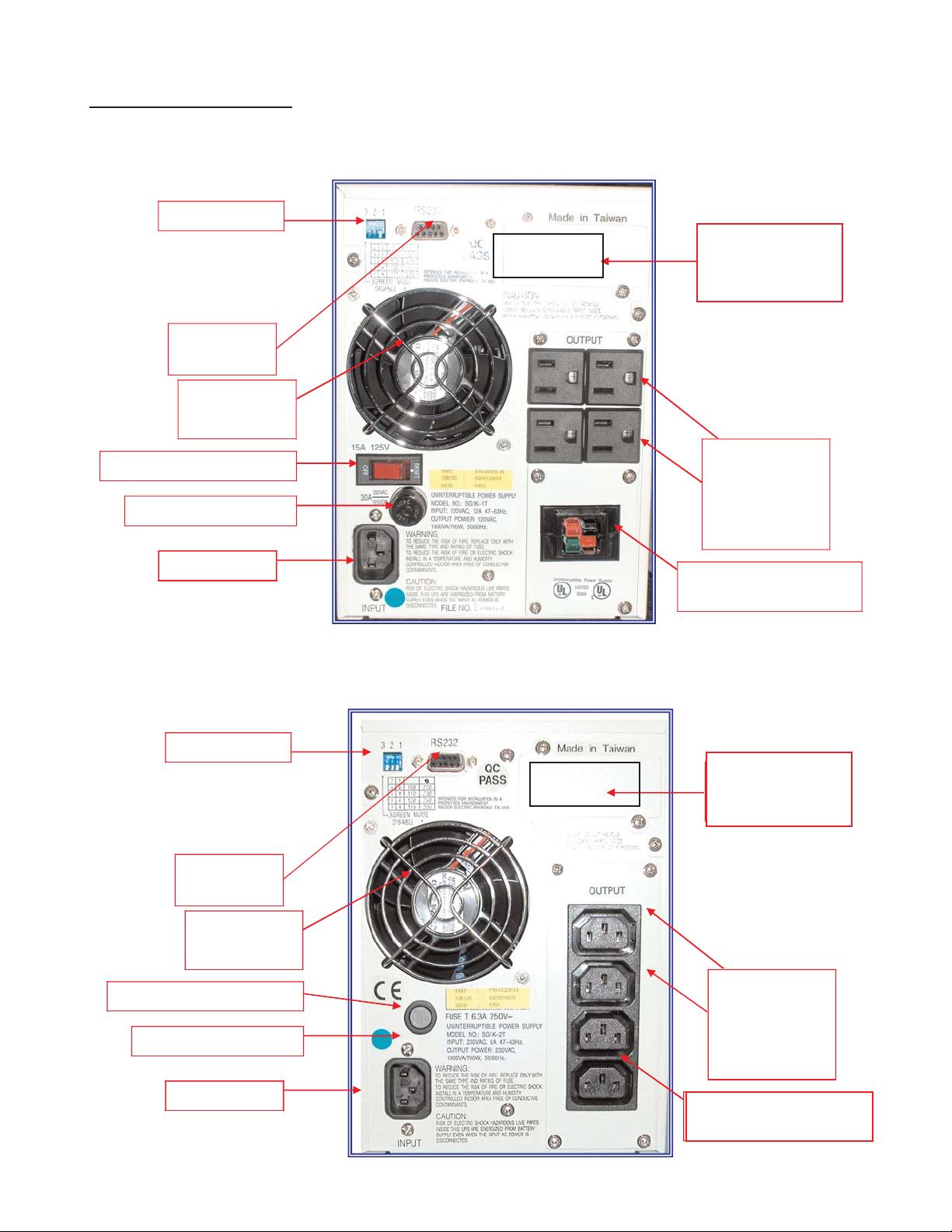
OPTIONAL EXTERNAL
BATTERY CONNECTOR
OUTPUT
RECEPTACLES
(6 places without
external battery
option, 4 places as
shown)
COVER PLATE
FOR
DIP SWITCHES
RS-232
CONNECTOR
COOLING FAN
DO NOT BLOCK
INPUT CIRCUIT BREAKER
BATTERY FUSE
POWER INLET
SG800-1T & SG1K-1T
Typical Rear Panel Overview
SG800-2T & SG1K-2T
Typical Rear Panel Overview
OPTIONAL EXTERNAL
BATTERY CONNECTOR
OUTPUT
RECEPTACLES
4 each IEC 320
COVER PLATE
FOR OPTION A L
SNMP AGENT
DIP SWITCHES
RS-232
CONNECTOR
COOLING FAN
DO NOT BLOCK
INPUT FUSE
BATTERY FUSE
POWER INLET
12
CHAPTER
CHAPTER44
REAR PANEL DETAILS
Please verify the UPS output rat-
ings match your
requirement
COVER PLATE FOR
OPTIONAL
COMMUNICATIONS
INTERFACE BAORD
COVER PLATE FOR
OPTIONAL
COMMUNICATIONS
INTERFACE BAORD
Page 15
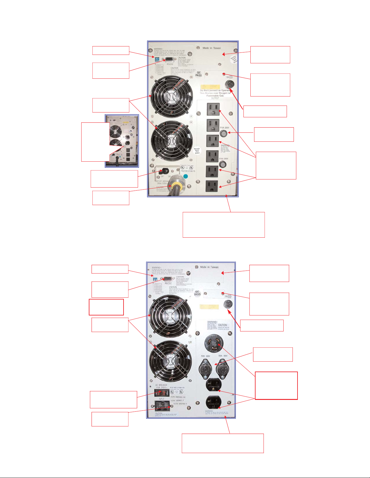
COVER PLATE FOR
OPTIONAL SNMP
AGENT
DIP SWITCHES
RS-232
CONNECTOR
COOLING FANS
DO NO BLOCK
MAIN POWER SWITCH
& INPUT CIRCUIT
BREAKER
INPUT LINE
CORD
OUTPUT FUSES
(2 places)
OPUTPUT
RECEPTACLES
(6) NEMA 5-15R
STANDARD
EXTERNAL
BATTERY
CONNECTOR
COVER PLATE
OTHER OUTPUT RECEPTACLE
CONFIGURATIONS ARE
AVAILABLE.
PLEASE CONSULT THE FACTORY
Optional
Receptacle
Configuration
Shown
Contact Factory
For Other
Configurations
COVER PLATE FOR
OPTIONAL SNMP
AGENT
DIP SWITCHES
RS-232
CONNECTOR
COOLING FANS DO
NO BLOCK
MAIN POWER SWITCH &
INPUT CIRCUIT BREAKER
LINE CORD INLET
OUTPUT FUSES
(2 places)
OPUTPUT
RECEPTACLES
Shown with (1) L6-20R
& (2) 5-20R Receptacles
EXTER NAL BATTERY
CONNECTOR COVER
PLATE
OTHER OUTPUT RECEPTACLE
CONFIGURATIONS AVAILABLE
SEE PAGE 23
SG1.5K-1T, SG2K-1T & SG3K-1T
Typical Rear Panel Overview
13
SG1.5K-2T, SG2K-2T & SG3K-2T
Typical Rear Panel Overview
OUTPUT
RECEPTACLES
Shown with (1) L6-20R &
(2) 6-20T Receptacles
COOLING FANS
DO NOT BLOCK
OUTPUT
RECEPTACLES
(6) NEMA 5-15R
STANDARD
BATTERYFUSE
BATTERYFUSE
Page 16
14
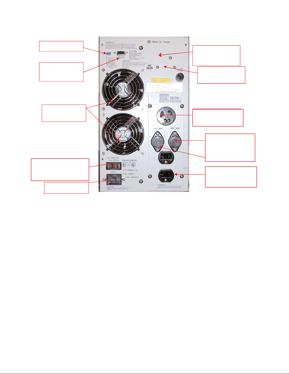
SG2K-2TXI & SG3K-2TX
Typical Rear Panel Overview
COVER PLATE FOR
COMMUNICATIONS
SLOT
EX TERNAL BATTERY
CONNECTOR COVER
PLATE
OUTPUT FUSES FOR
THE TOP RECEPTACLE
208-240Vac OUTPUT
RECEPTCALE
120Vac OU TPUT
RECEPTACLE
LINE CORD INLET
MAIN POWER SWITCH &
INPUT CIRCUIT
BREAAKER
COOLING FANS
DO NO BLOCK
RS-232
CONNECTOR
DIP SWITCHES
SG2K-2TXI Output Configuration
The SG2TXI model provides three galvanically isolated 240Vac and 120Vac outputs. The
two 120Vac receptacles are derived split phase from the isolated, center tapped 240Vac
output. The center tap has been grounded to provide a derived neutral for both 120Vac
outlets. Due to this, the 120V load is divided between the two 120Vac receptacles. The
combined load on all outputs must never exceed 1400 wats.
SG3K-2TX Output Configuration
The SG3K-2TX model provides galvanic isolation only on the 120Vac outlets. The 120Vac
outlets have been limited to a 1400 watt maximum output. The 208-240Vac output is
derived directly from the UPS inverter, which is not isolated. The combined load on all
outputs must never exceed 2100 watts.
BREAKER
MAIN POWER SWITCH &
INPUT CIRCUIT BREAKER
120Vac OUTPUT
RECEPTACLES
OUTPUT FUSES
(2) PLACES
208-240Vac
RECEPTACLE
Page 17
CHAPTER
CHAPTER55
COMMUNICATIONS INTERFACES
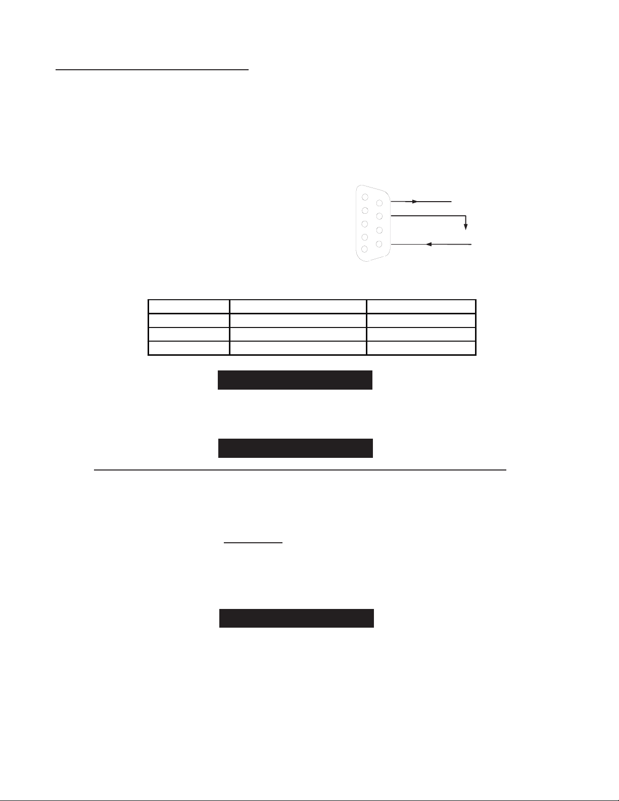
RS-232 INTERFACE
15
Pin #
Function explanation
I/O
9
RS 232 Rx
INPUT
6
RS 232 Tx
OUTPUT
7
Ground
Location:
The RS-232 interface is standard on all SG series UPS models. The port is
located on the UPS rear panel, via a DB-9 female connector.
Supported Protocols
UPSILON 2000 & SEC Smart Mon
BAUD RATE ------- 2400bps
DATA LENGTH---- 8 bits
STOP BIT----------- 1 bit
PARITY-------------- None
DB-9 Connector Pin Assignment
When making a connection between a computer and the UPS RS-232 port,
always use the green cable supplied with the UPS.
There are communications options that WILL
DISABLE the RS-232 port and
render it inoperable. The options are as follows:
a. Internal SNMP/HTTP agent option installed into the UPS
communications option slot.
The following options WILL
NOT affect the operation of the RS-232 port:
a. Falcon Opto Coupler based signal interface board installed to the
communications option slot.
b. Any Falcon relay based, dry contact signal interface board
installed into the communications option slot.
DB-9 Signals are not isolated and intended for connection to like RS-232
interfaces. DO NOT APPLY ANY OTHER VOLTAGES TO THESE PINS!
6
7
8
9
1
2
3
4
5
TX
RX
GEN
CAUTION
CAUTION
CAUTION
GND
Page 18
16
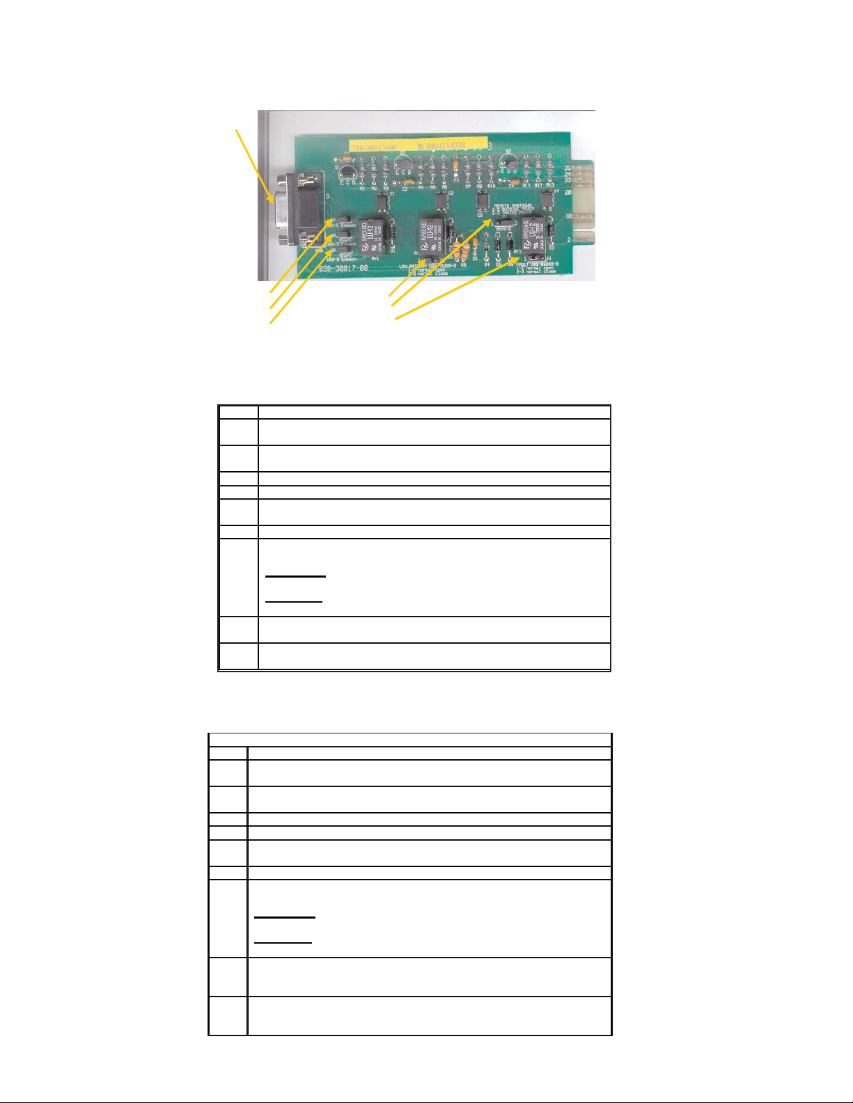
DRY CONTACT & OPTO COUPLER INTERFACE BOARD OPTIONS
JP1
JP2
JP3
J1
J2
J3
DB-9
Typical Falcon Dry Contact Relay Board
PIN
DESCRIPTION
1
Low Battery ( When UPS reaches low battery, contact activates)
(J1, 1-2 short = N.O) (J1, 2-3 short = N.C)
2
JP2 shorted = Low Battery common & all other shorted JP commons
JP2 open = common for low battery only
3
Utility Loss N.O. ( At loss of utility voltage, contact activates)
4
Utility Loss N.C. ( At loss of utility voltage, contact activates)
5
JP1 shorted = Utility Loss common & all other shorted JP commons
JP1 open = Utility Loss common only
6
Remote Shutdown common
7
Remote Shutdown
(J2, 1-2 short = outside power) (J2, 2-3 short = inside power)
1-2 shorted.
Applying an external 12V signal across the DB-9, pins six
and seven, while the UPS is on battery, will turn the UPS off.
2-3 shorted
. Applying a short directly across the DB-9, pins six and
seven, while the UPS is on battery, will turn the UPS off.
8
Alarm (Upon a UPS fault or failure the contact activates)
(J3, 1-2 short = N.O.) (J3, 2-3 short = N.C.)
9
JP3 shorted = Alarm common & all other shorted JP commons
JP3 open = Alarm common only
PIN & JUMPER ASSIGNMENT FOR THE FALCON
UA88374 RELAY OPTION BOARD
(no on-bypass signal)
PIN & JUMPER ASSIGNMENT FOR THE FALCON
UA88376 RELAY OPTION BOARD
(with on-bypass signal)
DB-9F PIN & JUMPER ASSIGNMENTS
PIN
DESCRIPTION
1
Low Battery ( When UPS reaches low battery, contact activates)
(J1, 1-2 short = N.O) (J1, 2-3 short = N.C)
2
JP2 shorted = Low Battery common & all other shorted JP commons
JP2 open = common for low battery only
3
Utility Loss N.O. ( At loss of utility voltage, contact activates)
4
Utility Loss N.C. ( At loss of utility voltage, contact activates)
5
JP1 shorted = Utility Loss common & all other shorted JP commons
JP1 open = Utility Loss common only
6
Remote Shutdown common
7
Remote Shutdown
(J2, 1-2 short = outside power) (J2, 2-3 short = inside power)
1-2 shorted.
Applying an external 12V signal across the DB-9, pins six
and seven, while the UPS is on battery, will turn the UPS off.
2-3 shorted
. Applying a short directly across the DB-9, pins six and
seven, while the UPS is on battery, will turn the UPS off.
8
On Bypass or Alarm (Upon the UPS going to bypass or a UPS failure
the contact activates)
(J3, 1-2 short = N.O.) (J3, 2-3 short = N.C.)
9
JP3 shorted = On bypass, Alarm common & all other shorted JP
commons
JP3 open = On bypass, Alarm common only
Page 19
17
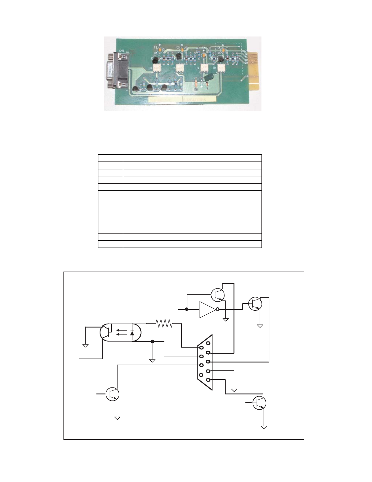
PIN ASSIGNMENT FOR THE FALCON
UA88373 OPTO-COUPLER OPTION BOARD
(no-bypass signal)
PIN
DESCRIPTION
1
Not Used
2
Utility Loss (N.O.) (Closes upon utility loss)
3
Utility Loss (N.C.) ( Opens upon utility loss)
4
Common for pins 2, 3 & 5
5
Low Battery (N.O.) (Closes at low battery)
6
Remote Shutdown
Applying a +5-+12Vdc voltage level for >500ms,
while the UPS is on battery will shutdown the
UPS
7
Not Used
8
Not Used
9
Not Used
Typical Falcon Opto-coupler Interface Card
(A)
(E)
(K)(B)
(C)
6
7
8
2
3
4
5
To CPU
Alar m Signal
DB-9
Low Battery Signal
Utility L o ss
OPTO Board Internal Circuitry
Page 20
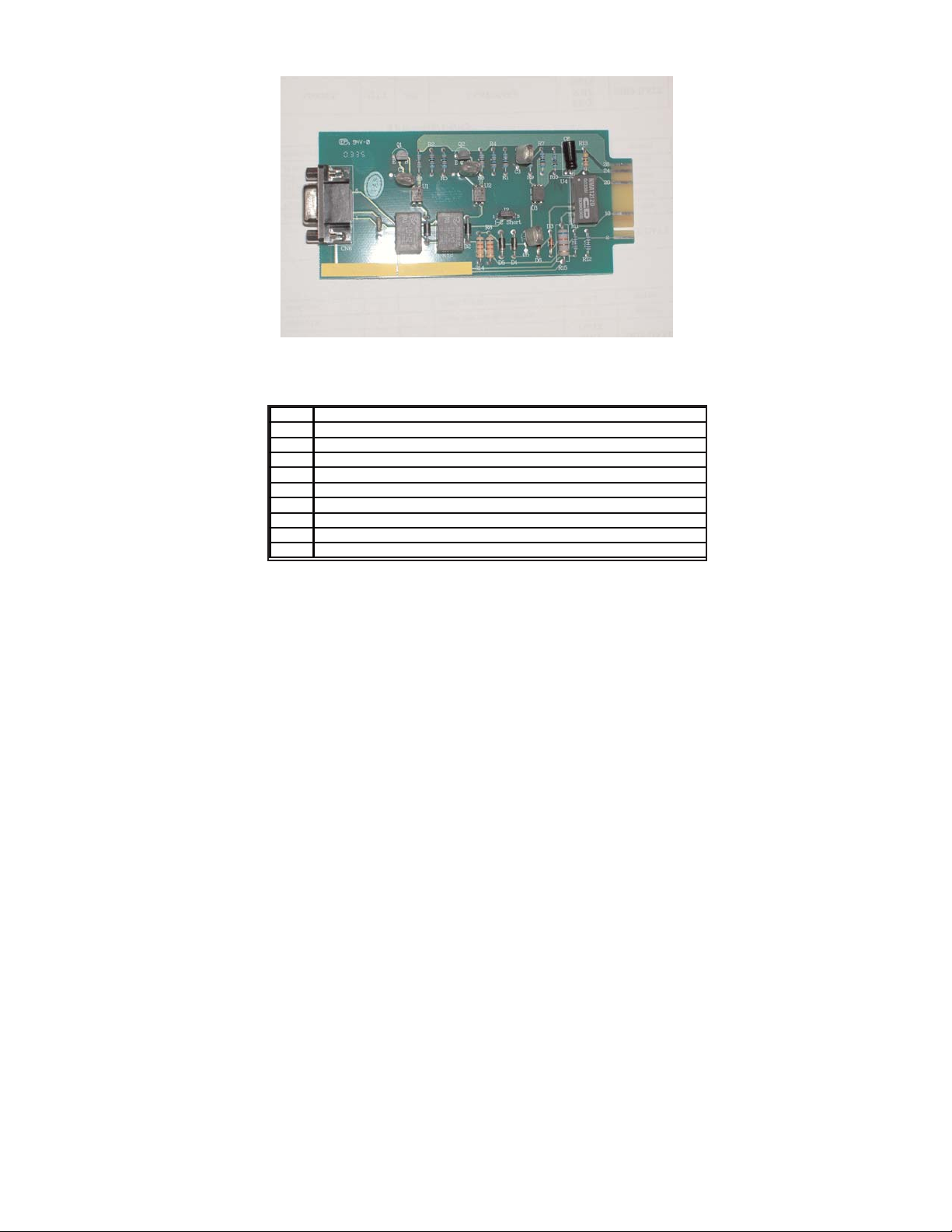
APC Style Dry Contact Relay Board
PIN
DESCRIPTION
1
Remote Shutdown (on battery operation only)
2
Remote Shutdown Common
3
Not Used
4
Low Battery Common
5
Low Battery (N .O.)
6
Not Used
7
Not Used
8
Utility Fail (+/- 10Vdc)
9
Utility Fail (+/- 10Vdc)
PIN & JUMPER ASSIGNMENT FOR THE FALCON
UA88377 RELAY OPTION BOARD
(APC Style Board)
18
Page 21

CHAPTER
CHAPTER66
Maintenance &
Technical Support
1. Care & Maintenance
Falcon®SG Series UPSs are designed to be maintenance-free. They can be
cleaned with a damp cloth or non-abrasive cleanser, providing the UPS is
turned off and the input plug is disconnected from the utility source.
On a regular basis, check the vents to make sure they are kept free from
accumulation of dust, dirt or lint.
2. Battery Life vs. Temperature
For full battery life, keep the UPS close to an ambient temperature of 77ºF.
The batteries should never be exposed to temperatures below 40ºF and above
104ºF.
.
3. Battery Replacement
This UPS contains sealed maintenance-free batteries (VRLA). When situated in
a typical office environment, with the proper charging and limited cycling, the
batteries can last many years. In home, office or computer room
environments, the batteries should be replaced every three to five years.
Should you require battery replacement contact the Falcon Service Department
(see page 20 for contact information).
Never attempt to service batteries. High voltage exists within the unit, which
could cause electrical shock. Servicing of batteries should be performed or
supervised by personnel knowledgeable of batteries and the required
precautions. Keep unauthorized personnel away from batteries.
When replacing the UPS batteries, use the same number and type of batteries.
A. NEVER dispose of batteries in a fire, as batteries will explode.
B. NEVER dispose of used batteries or the UPS in the trash or landfill as it is
against federal and state laws. The UPS and Batteries must be recycled.
For UPS and battery recycling information, please contact our service
department for the name and address of the nearest battery recycling facility.
A. Do not open or mutilate the battery or batteries. Released electrolyte is
harmful to the skin and eyes. It may be toxic.
B. Abattery can present a risk of electrical shock and high short circuit current.
REFER ALL BATTERY SERVICING OR REPLACEMENT TO A QUALIFIED
SERVICE TECHNICIAN. NEVER ATTEMPT TO REPLACE THE
BATTERIES YOURSELF.
WARNING
NEVER
CAUTION
19
Page 22

The following precautions should be observed by a qualified technician when
working with batteries.
1. Remove watches, rings, or other metal objects.
2. Use tools with insulated handles.
3. Wear rubber gloves and boots.
4. Do not lay tools or metal parts on top of batteries.
4. Storing the UPS and Batteries
Should you need to store the UPS for a long period, fully recharge the battery
just prior to storage and recharge the battery every 4 months by plugging the
UPS into a power outlet. It is recommended that the batteries charge for 24
hours after long-term storage.
5. FCC Considerations
This equipment generates and uses radio frequency energy and if not installed
and used properly in strict accordance with the manufacturer's instructions,
may cause interference to radio and television reception. All models covered in
this manual have been tested and found to comply with the limits for a Class A
computing device, in accordance with the specifications in FCC regulations,
Part 15, Subpart J, which are designed to provide reasonable protection
against such interference.
If this equipment does cause harmful interference to radio or television
reception, which can be determined by turning the equipment off and on, the
user is encouraged to try to correct the interference by one or more of the
following measures:
a. Reorient or relocate the receiving antenna.
b. Increase the separation between the equipment and the receiver.
c. Connect the equipment into an outlet on a circuit different from that to
which the receiver is connected.
d. Consult the dealer or an experienced radio/television technician for
assistance.
20
Page 23

6. Technical Support
Your FALCON®Electric SG Series UPS is backed by one of the finest customer
service teams assembled. Write, call, fax or email should you require
technical assistance or service.
Falcon Electric Inc.
5106 Azusa Canyon Road
Irwindale, CA. 91706
Service 800.842.6940
Voice 626.962.7770
Fax 626.962.7720
Email: [email protected]
WWW.FALCONUPS.COM
Please have your UPS model, serial numbers and date of purchase on hand
prior to your call. This information is located on the identification label on the
rear panel of the unit. This information is essential in retrieving your unit’s
historical records. Should our service department determine service is required,
you will be given a Return Material Authorization number (RMA) along
with return shipping instructions.
The RMA number issued must appear on the outside of the shipping carton.
The original shipping container must be used when returning any SG
Series product. Falcon
®
Electric will not assume any responsibility for shipping
damage. In the event of shipping damage, you will be notified of the damage
and be instructed to file a claim with the freight carrier. You will be billed for all
repairs caused by the shipping damage. You must submit a copy of our repair
invoice to the carrier for reimbersment.
All units must be returned prepaid. The address and shipping instructions will
be given to you at the time the RMA is issued.
7. Requesting Technical Information or Support
You may request technical information or support by email or telephone.
Please send your technical or support questions by email to:
You may contact a FALCON support engineer directly by calling the FALCON
support line between 9:00 am and 4:00 pm PST.
800.842.6940
8. FALCON Web Support
Product data sheets, specification and owner’s manuals are available in
Adobe
®
Acrobat .PDF format on our corporate website.
WWW.FALCONUPS.COM
21
Page 24

GENERAL PROVISIONS
FALCON® ELECTRIC INC., hereby warrants product shipped under this agreement to be free from defective workmanship for a period of two years
following date of shipment. This Limited New Product Warranty Agreement only applies to covered repairs to the product occurring within the United
States and Canada.
EXCLUSIONS:
The following are not covered by the Falcon Electric Limited New Product Warranty:
1. DAMAGE DUE TO ACCIDENTS, FRAUD, INTENTIONAL NEGLIGENCE, MISUSE, IMPROPER INSTALLATION,
UNAUTHORIZED ADJUSTMENTS, MODIFICATIONS, ALTERATIONS, DISCONNECTION, TAMPERING: Accidents or acts of
nature or other events beyond the control of Falcon Electric, damage from impact, contaminants, fire, or water, misuse of the
product such as sustained overloading, improper installation or operation, operation in an uncontrolled environment.
2. DAMAGE DUE TO IMPROPER INSTALLATION OR LACK OF MAINTENANCE: Lack of proper maintenance as outlined in the
owner's manual.
3. NORMAL MAINTENANCE: Cleaning, replacement of leaking or outdated batteries.
4. DAMAGE DUE TO ALTERATIONS: Alterations by changing or adding to the product by any unauthorized personnel or service
organization.
5. DAMAGE CAUSED BY OTHER THAN ORIGINAL EQUIPMENT PARTS. Any malfunctions caused by the use of other than Falcon
Electric original equipment parts such as batteries, line cords and plugs, output receptacles, or any other part.
6. BROKEN OR TAMPERED WARRANTY SEALS: Falcon Electric will deem all warranties null and void in the event warranty seals
are broken or show signs of removal or tampering.
7. CONSEQUENTIAL DAMAGES: This Limited New Product Warranty does not cover any consequential or secondary damages that
may be suffered as a result of usage of the product or the need to repair or replace a warranted part except to the extent coverage
of such damage is required by the state whose law governs the Falcon Electric Limited New Product Warranty.
8. REPAIRS BY UNAUTHORIZED SERVICE ORGANIZATIONS OR PERSONNEL: Otherwise covered repairs when the prescribed
repair is not performed by the Falcon Electric Service Center or by a Falcon Electric authorized third party service organization.
9. LIABILITY FROM USE OF THE PRODUCT: Liability for damage to property or injury or death of any person arising out of the
operation, maintenance, or use of the product weather.
10. Warranty void if the battery is allowed to discharge below the minimum battery cutoff point. To prevent such discharge, remove the
battery fuse, or switch the battery disconnect to the off position when the unit is to be stored without the AC power being supplied
to the UPS for more than two days. The battery must be recharged every three to four months when not in use.
11. This product is not recommended, and Falcon Electric Inc. will not knowingly sell this product, for use with life support and other
designated “critical devices". ANY SUCH USE BY A USER AUTOMATICALLY VOIDS AND DISCLAIMS ANYAND ALL
WARRANTIES, INCLUDING ANY IMPLIED WARRANTY OF MERCHANTABILITY, IMPLIED WARRANTY OF FITNESS FOR A
PARTICULAR PURPOSE, AND EXPRESS WARRANTIES THAT THIS PRODUCT WILL CONFORM TO ANYAFFIRMATION OR
PROMISE, FOR THIS PRODUCT AND THE USER AGREES THAT IN NO EVENT SHALL FALCON ELECTRIC INC. BE LIABLE
FOR CONSEQUENTIAL OR INDIRECT DAMAGES.
LIMITS OF LIABILITY:
LIMITATION OF LIABILITY: THERE IS NO LIABILITY FOR INCIDENTAL OR CONSEQUENTIAL LOSS OR DAMAGE UNDER THESE
WARRANTIES INCLUDING BUT NOT LIMITED TO, LIABILITY FOR INJURY, LOSS OF LIFE, PROPERTY DAMAGE, LOSS OF USE, LOSS
OF DATA, LOSS OF TIME, INCONVENIENCE OR COMMERCIAL LOSS, OR BREACH OF IMPLIED OR EXPRESSED WARRANTIES. ANY
AND ALL SUCH LIABILITY IS EXPRESSLY EXCLUDED. IN NO EVENT SHALL FALCON ELECTRIC BE RESPONSIBLE FOR ANY
AMOUNT EXCEEDING THE ACTUAL MARKET VALUE OF THE PRODUCT. Some states do not permit the exclusions of limitations of
incIdental or consequential damages, so these limitations may not apply to you.
TRANSFER:
This Falcon Electric Limited New Product Warranty is not transferable in the event of the product ownership being transferred during the warranty coverage period.
ITEM COVERAGE:
Effective January 1, 2000, FALCON® ELECTRIC hereby warrants product shipped under this Agreement to be free from defective workman
ship for a period of two years following date of shipment. Coverage under this Falcon Electric New Product Warranty Agreement commences
with the date of shipment defined as the date on the Bill of Lading. If no Bill of Lading is issued, the date of shipment shall be shown on
seller's shipping document. The Falcon Electric Limited New Product Warranties expire two years from the aforementioned commencement
date. Falcon Electric Inc. reserves the right to make changes, additions, and/or other improvements in its products without incurring any
obligation to install them on its products previously sold. This Warranty is valid for product as sold.
1. For product located in the continental United States and Canada deemed by Falcon Electric to be covered under this warranty,
Falcon Electric will pay shipping costs associated with the return and repair of product under the following conditions only:
a. Falcon Electric will pay shipping costs both to and from our U.S. Service Center for the first 30 days from the original
date of invoice. During this 30 day period, Falcon Electric may elect to ship a new unit to replace the defective product.
b. After the first 30 days and up to 90 days from the original date of invoice, the end-user is responsible for shipping costs
associated with sending the defective unit to the Falcon Electric U.S. Service Center. Falcon Electric will pay shipping
costs associated with returning the repaired product to the end-user. During this 60 day period Falcon Electric may elect
to offer a loaner unit, providing the end-user agrees to pay for all shipping costs associated with transportation of the
loaner unit both from and return to the Falcon Electric U.S. Service Center.
c. All shipping costs for product submitted beyond 90 days of the original date of invoice is the responsibility of the end-
user.
WARRANTY
22
Page 25

SG Series
TM
UPS PLUS
®
800VA to 1.5kVA
Model Number
SG800-1T
SG1K-1T
SG1K-2T
SG1.5K-1T
Nominal VA
800
1000
1000
1500
Electrical Input
Nominal AC Voltage
120V
120V
230V
120V
AC Voltage Range
87-140V
87-140V
170-275V
87-140V
Current -Am ps
5.5
6.9
3.6
10.7
Frequency
50/60 Hz ± 5% (Auto – Tracking)
Power Factor Correction
> 0.95
Efficiency (Typical)
> 86%
Electrical Output
Watts
560
700
700
1050
AC Voltage
(Switchable)
100V
110V
115V
120V
100V
110V
115V
120V
200V
220V
230V
240V
100V
110V
115V
120V
Frequency
50/60 Hz (Auto Tracking )
Frequency Stability
±0.3% (Battery Mode)
Voltage Regulation
± 2%
Step Load Change
± 7% for 100% load variation
Harmonic Distortion
< 3% Linear Load, < 5% Non -Linear Load
Overload
105% load for 50 Seconds
Crest Ratio
3:1
Battery
DC Voltage
36V
72V
Type
12V, 7AH Sealed Lead Acid Maintenance -Free
Back Up Time @ Full Load
@ 1/2 Load
9 Minutes
25 Minutes
6 Minutes
19 Minutes
11 Minutes
30 Minutes
Recharge Time
8 Hours to 90%
Battery times are approximate.
Transfer Time
Line Fails/Recovers
Zero
UPS to Bypass or Reve rse
< 4ms
After Overload
Auto Transfer to UPS
Electrical Connections
Input
6’ Cord with
5-15P
6’ Cord with
5-15P
6’ Cord with
Schuko or 6-15P
6’ Cord with
5-15P
Output
(6) 5-15R
(6) 5-15R
(4) IEC 320
(6) 5-15R
Contact the fa ct o ry for other input/output optio ns .
Environmental
Operating Temperature
0º C - 40º C (32º F to 104º F)
Humidity
10% to 95% Non – Condensing
Altitude
7,000 Feet
Cooling
Low Velocity Forced Air Fans
Audible Noise @ 1 Meter
<45dBA
< 50dBA
Controls and Indicators
LED
Line, Inverter, Battery Reserve, Load, Bypass, Alarm, Crest, Battery & Load Capacity Level
Audible Alarms
DC Mode, Low Battery, Over/Under Voltage, Over/Under Frequency, High Temp., Over Load, Fau lt Alarm
Communications
RS-232 Serial Port (Bundled UPSilon 2000 Software)
Mechanical
Dimensions H x W x D inches
(mm)
8.7 x 6.0 x 15.8
(220.9 x 152.4 x 401.3)
13.8 x 7.6 x 18.9
(350.5 x 193.0 x 480 .0)
Weight lb. (kg)
33 (14.9)
68 (30.9)
Agency Listing
UL 1778, CUL,
FCC Class A
CE available with Schuko
plug only
UL 1778, CUL,
FCC Class A
Available Options
Option A
60 Hz to 50 Hz Frequency Conversion
Option B
50 Hz to 60 Hz Frequency Conversion
Option C
SNMP/HTTP Network Card (Internal)
Option D
Standard Contact Closure Interface Card
Maintenance Bypass
Make-Before-Break External Wrap Around
External Battery Packs
Extended Run Time Battery Packs (minut es to hours)
Fast Battery Charger
Fast Charger internal to the Extended Battery Pack Cabinet (Required for battery times 2 hours or more.)
23
Page 26

SG Series
TM
UPS PLUS
®
2kVA & 3kVA
Electrical Input
Nominal AC Voltage
120V
230V
120V
230V
230V
AC Voltage Range
87 – 140V
170 – 275V
87 – 140V
170 – 275V
170 – 275V
Current – Amps
14.2
7.4
21.4
11.2
7.5
11.3
Frequency
50/60 Hz ± 5% (Auto – Tracking)
Power Factor Correction
> 0.95
Efficiency (Typical)
> 86%
> 85%
Electrical Output
Watts
1400
2100
1400
2100
AC Voltage
(Switchable)
100V
110V
115V
120V
200V
220V
230V
240V
100V
110V
115V
120V
200V
220V
230V
240V
120V
(700W
each
5-20R)
208V
220V
230V
240V
120V
(1400W
Max.)
208V
220V
230V
240V
Frequency
50/60 Hz (Auto Tracking )
Frequency Stability
± 0.3% (Battery Mode)
Voltage Regulation
± 2%
± 5%
± 3%
Step Load Change
± 7% for 100% load v ariation
Harmonic Distortion
< 3% Linear Load, < 5% Non -Linear Load
Overload
105% load for 50 Seconds
Crest Ratio
3:1
Battery
DC Voltage
72V
96V
Type
12V, 7AH Sealed Lead Acid Maintenance -Free
Back Up Time @ Full Load
@ 1/2 Load
7 Minutes
20 Minutes
5.5 Minutes
15 Minutes
7 Minutes
20 Minutes
5.5 Minutes
15 Minutes
Recharge Time
8 Hours to 90%
Battery times are approximate.
Transfer Time
Line Fails/Recovers
Zero
UPS to Bypass or Reve rse
< 4ms
After Overload
Auto Transfer to UPS
Electrical Connections
Input
6’ Cord with
5-20P
6’ Cord with
6-20P, L6-20P
or Schuko
6’ Cord with
L5-30P
6’ Cord with
6-20P, L6-20P
or Schuko
6’ Cord with 6-20P, L6-20P
or Schuko
Output
(6) 5-15R or
(3) 5-15R &
(2) 5-20R
(6) IEC 320
or (1) L6-20R
(6) 5-15R or
(3) 5-15R &
(2) 5-20R
(6) IEC 320
or (1) L6-20R
(2) 5-20R & (1) L6-20R
Contact the fa ct o ry for other input/output optio ns .
Environmental
Operating Temperature
0º C - 40º C (32º F to 104º F)
Humidity
10% to 95% Non – Condensing
Altitude
7,000 Feet
Cooling
Low Velocity Forced Air Fans
Audible Noise @ 1 Meter
<50dBA
Controls and Indicators
LED
Line, Inverter, Battery Reserve, Load, Bypass, Alarm, Crest, Battery & Load Capacity Level
Audible Alarms
DC Mode, Low Battery, Over/Under Voltage, Over/Under Frequency, High Temp., Over Load, Fault Alarm
Communications
RS-232 Serial Port (Bundled UPSilon 2000 Software)
Mechanical
Dimensions H x W x D inches (mm)
13.8 x 7.6 x 18.9 (350 x 193 x 480)
13.8 x 7.6 x 30.0 (350 x 193 x 720)
Weight lb. (kg)
68.4 (31)
81.4 (37)
150.0 (68)
Agency Listing
-1T Models: UL 1778, CUL, FCC Class A
-2T Models: UL 1778, CUL , FCC Class A; CE
available with Schuko p lug only
UL 1778, CUL, FCC Class A
Available Options
Option A
60 Hz to 50 Hz Frequency Conversion
Option B
50 Hz to 60 Hz Frequency Conversion
Option C
SNMP/HTTP Network Card (Internal)
Option D
Standard Contact Closure Interface Card
Maintenance Bypass
Make-Before-Break External Wrap Around
External Battery Packs
Extended Run Time Battery Packs (minutes to hours)
Fast Battery Charger
Fast Charger internal to the Extended Battery Pack Cabinet (Required for battery times 2 hours or more.)
Model Number
SG2K-1T
SG2K-2T
SG3K-1T
SG3K-2T
SG2K-2TXI
SG3K-2TX
Nominal VA
2000
3000
2000
3000
24
 Loading...