

Falcon SG2KRM-1SC, SG700-1SC, SG3KRM-1SC, SG1K-1SC, SG1.5K-1SC User Manual
...
SC On-line UPS
User’s Manual
Rack / Tower Models
700VA to 3kVA, 120Vac
© 2016 Falcon® Electric, Inc. All rights reserved.
All other brand names and trademarks are the property of their respective owners.
The information stated in this document is subject to change without notice.
Falcon®, Falcon® Electric and UPS logos are registered trademarks of Falcon Electric, Inc.
OM480039 SC1-3KR_T 120V_12-12-16 REV.NR
Proprietary: The information contained herein is proprietary to Falcon Electric, Inc. and
shall not be reproduced or disclosed in whole or in part or used for any reason except
when such user possesses direct, written authorization from Falcon Electric, Inc.
The statements contained herein are based on good faith assumptions and provided for
general information purposes only. These statements do not constitute an offer, promise,
warranty or guarantee of performance. Actual results may vary depending on certain
events or conditions. This document should not be used or relied upon for any purpose
other than that intended by Falcon Electric, Inc.

1
Table of Contents
1. Safety and Storage Instructions ....................................................................... 2
1.1 Safety ....................................................................................................... 2
1.2 Storage ..................................................................................................... 3
2. Product Introduction.......................................................................................... 4
2.1 General Characteristics............................................................................ 4
2.2 Special Features ...................................................................................... 5
3. UPS Functional Descriptions ............................................................................ 6
3.1 Front Panel Display .................................................................................. 6
3.2 Rear Panel ............................................................................................. 11
3.3 Communication Port ............................................................................. 12
4. Installation and Operation ............................................................................... 13
4.1 Unpacking .............................................................................................. 13
4.2 Installation Location ............................................................................... 16
4.3 Operation ............................................................................................... 17
5. UPS System Architecture and Operating Modes ........................................... 31
6. Maintenance Guide......................................................................................... 32
6.1 Troubleshooting ..................................................................................... 32
6.2 Error Code Definitions ............................................................................ 35
6.3 Maintenance ........................................................................................... 35
7. Communication Software ............................................................................... 36
7.1 Hardware Setup ..................................................................................... 36
7.2 Software Installation ............................................................................... 36
8. Optional Communication Cards ...................................................................... 37
8.1 R2E (second RS-232) card .................................................................... 37
8.2 USE (USB) card ..................................................................................... 37
8.3 DCE (Dry Contact) card ......................................................................... 38
8.4 SNMP Cards .......................................................................................... 39
9. Falcon Electric Service.……………………………………………….…………..40
9.1 Contact Information……….…………………………………………….….. 40
10. Warranty…..………………………………………………..………………….……41

2
Safety and Storage Instructions
1.1 Safety
SAVE THESE INSTRUCTIONS: This manual contains instructions that should be
followed during installation and maintenance of the UPS and Batteries.
1. WARNING: Risk of electric shock. Do not remove cover. No user serviceable
parts inside. Refer servicing to qualified service personnel.
2. Avoid spilling liquids or allowing foreign objects to fall into the UPS as it will
cause damage, possibly subject users to electric shock, and invalidate your
warranty.
3. The UPS must be installed in a clean, indoor environment, free from moisture,
flammable gasses, fumes or corrosive substances.
4. This UPS is equipped with an EMI filter. To prevent potential leakage current
hazards, ensure that the AC mains supply is securely grounded.
5. This UPS is designed to be installed and commissioned in a controlled
environment as follows:
- Operating temperature 0°C to 40°C (32°F to 104°F) and 10% to 90% relative
humidity. High ambient temperature significantly reduces battery life.
- Avoid direct sunlight.
- Do not install the UPS in a flammable or otherwise hazardous environment.
-
Avoid vibration and areas subject to physical impact.
- The maximum UPS output load (in watts) must never exceed that shown on
the UPS rating label. NEVER CONNECT equipment that could overload the
UPS or demand half-wave rectification from the UPS output, for example:
electric drills, vacuum pumps, or hair dryers.
6. To prevent overheating of the UPS, keep all ventilation openings free from
obstruction. Do not place anything on top of the UPS. Keep the UPS rear
panel at least 8 inches away from the wall or other obstructions.
7. Install the UPS in a well ventilated area, ideally exchanging 2.9 cubic feet of
air per minute, because the chemical reaction during battery charging causes
trace gas production.
8. If the product emits a strange noise or smell, immediately stop using the
product and contact Falcon Electric for service or repair.
9. Always switch off the UPS and disconnect the batteries when relocating the
UPS. Be aware that, even when disconnected, charged batteries present a
risk of electric shock.
10. The UPS should be recharged every 2-3 months if unused. When installed
and being used, the batteries will be automatically recharged.

3
11. Ensure that the input voltage to the UPS is within the specified range. Use a
certified input power cable with the correct plugs and sockets for the system
voltage.
12. CAUTION: Risk of Energy Hazard, 12V, 9 Ampere-hour batteries. Before
replacing batteries, remove conductive jewelry such as chains, wrist watches
and rings. High energy through conductive materials could cause severe
burns.
13. CAUTION: Do not dispose of batteries in a fire. They may explode.
14. CAUTION: Do not open or mutilate batteries. Released material is harmful to
the skin and eyes. It may be toxic.
15. Servicing of batteries should be performed or supervised by personnel
knowledgeable about batteries and the required precautions.
16. CAUTION: A battery can present a risk of electrical shock and short circuit
current. The following precautions should be observed when working on
batteries:
a) Remove watches, rings or other metal objects
b) Use tools with insulated handles
c) Wear rubber gloves and boots
d) Do not lay tools or metal parts on top of the batteries
e) Disconnect charging source prior to connecting or disconnecting battery
terminals.
f) Determine if battery is inadvertently grounded. If inadvertently grounded,
remove source from ground. Contact with any part of a grounded battery
can result in electrical shock. The likelihood of such shock can be reduced
if such grounds are removed during installation or maintenance.
1.2 Storage
If the UPS is unused for an extended period of time, it must be stored in a
moderate climate. The batteries should be charged for 12 hours every 3 months by
connecting the UPS to the utility supply. Repeat this procedure every 2 months if
the storage ambient temperature is above 25°C (77°F).

4
Product Introduction
2.1 General Characteristics
1. True On-Line technology continuously supplies your critical device with
stable, regulated, transient-free, pure sine wave AC power.
2. High-efficiency PWM sine-wave topology yields excellent overall
performance.
3. The high crest factor of the inverter can handle high inrush current loads
without the need to upgrade the power rating.
4. User-friendly plug-and-play design allows hassle-free installation.
5. Built-in maintenance-free, sealed batteries minimize the need for aftersales service.
6. To protect the unit from overloading, the UPS will automatically switch to
bypass mode in 30 seconds if loading is above 105% of rated capacity. It
will automatically switch back to inverter mode once the overload
condition ceases.
7. Should the output become short-circuited, the UPS puts the system in
standby mode, provides visible and audible alarms, and cuts the output
supply automatically until the short circuit situation is resolved manually.

5
2.2 Special Features
1. Our High Frequency Transformer-less technology and tower-convertible
form factor enables the UPS to be integrated into environments with space
constraints.
2. This UPS is equipped with fully digital control logic for greater functionality
and enhanced power protection. Digital signal processing (DSP) also
provides the UPS with powerful communication capability, which simplifies
remote control and monitoring.
3. Our wide input voltage tolerance of 90-150Vac allows under-voltage or
over-voltage correction without unnecessary battery drain and helps
extend battery life.
4. Our DC-start function ensures the start-up of the UPS even during power
outages.
5. Our smart battery management system maximizes overall battery life.
6. Our Active Power Factor Correction control function constantly maintains
the UPS input power factor at > 0.9 for superb energy efficiency.
7. Our Selectable Bypass input voltage tolerance (sensitivity low / high)
prevents under or over-voltage being supplied to the loads in bypass mode.
The selectable voltage ranges are (i) Bypass Sensitivity Low:
±15% of
available output voltage setting and (ii) Bypass Sensitivity High:
±10% of
available output voltage setting. For example, if the output voltage setting
is 120V, the Bypass Sensitivity Low range is 120Vac ±15%, i.e., 102 - 138
Vac.
8. The UPS provides numerous configurable output voltages to match
various system voltage requirements.
9. The UPS is designed to comply with various stringent international
standards for electromagnetic interference compatibility (EMC).
6
UPS Functional Descriptions
3.1 Front Panel Display
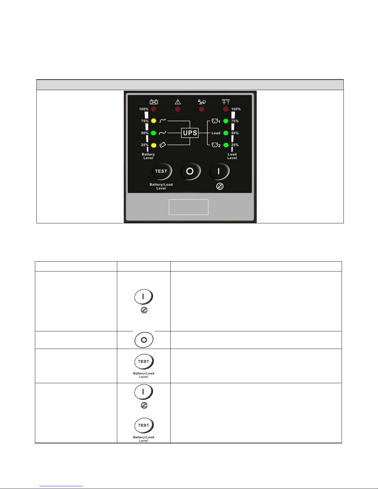
3.1.1 SC UPS< Convertible Type (Rack / Tower)> LED Panel (Optional, Contact
Falcon Electric for availability.)
LED Panel
Control Key
Symbol
Description
ON (Alarm Silence)
a. UPS Power-On Switch
(Press and hold until the buzzer beeps.)
b. Alarm silence
c. Error Code Display Function Mode.
After an alarm, press to mute the alarm buzzer
and show an Error Code. (Do not hold for > 1
second.)
OFF
UPS Power-Off Switch
(Press and hold until the buzzer beeps.)
Self-Test
a. Commands the UPS to perform a battery self-
test. (Press and hold until the buzzer beeps.)
b. Battery and Load Display Function Mode
(Do not hold for > 1 second.)
◎ Manual Bypass
+
Press the "ON" key and "Self-Test" key
simultaneously for 3
seconds to transfer from
"Inverter to Bypass" (The bypass LED will
continuously blink and the buzzer will beep
intermittently.) or "Bypass to Inverter" when the
UPS is in online mode and the Bypass Voltage
Window is Normal.
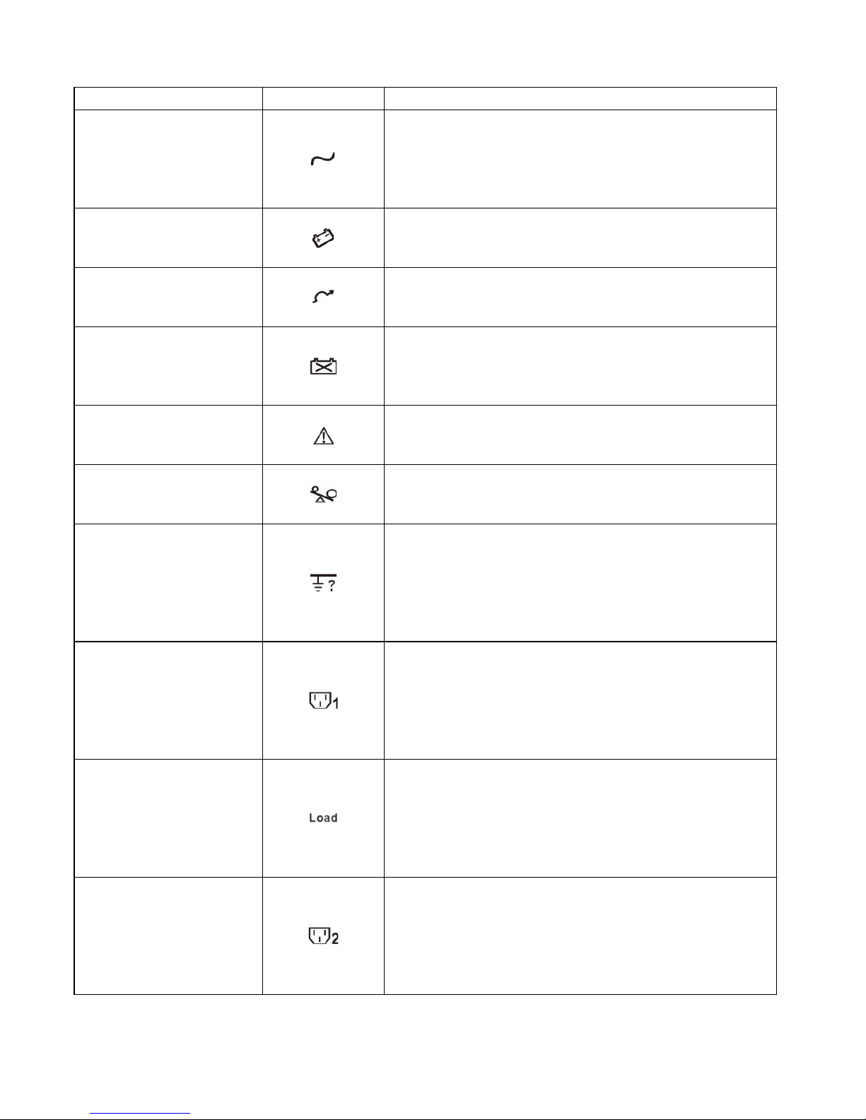
7 LED Indicator
Symbol
Description
Normal Mode LED
1. Solid indicates normal utility voltage. Blinking
indicates insufficient utility voltage for the full
load. Off indicates abnormal utility voltage.
2. In Battery and Load Function Mode, indicates
battery capacity is 50%.
Battery Mode LED
1. Indicates load supplied by battery power.
2. In Battery and Load Function Mode, indicates
battery capacity is 25%.
Bypass Mode LED
1. Indicates load supplied by bypass.
2. In Battery and Load Function Mode, indicates
battery capacity is 75%.
Battery low / fault
LED
1. Indicates low battery power or faulty battery
bank.
2. In Battery and Load Function Mode, indicates
battery capacity is 100%.
Fault LED
1. Solid indicates fault or abnormal condition.
2. Blinking
indicates LED Panel in Error Code
Function Mode.
Overload LED
1. Indicates UPS is overloaded.
2. In Error Code Function Mode, indicates Error
Code 16.
Site wiring fault LED
1. Indicates reversed polarity or high neutral-
ground voltage.
2. In Battery and Load Function Mode, indicates
load capacity is 100%.
3. In Error Code Function Mode, indicates Error
Code 8.
Outlet 1 LED
1. Indicates UPS Outlets 1 are enabled and
ready to supply loads. (This function is optional.)
2. In Battery and Load Function Mode, indicates
load capacity is 75%.
3.
In Error Code Function Mode, indicates Error
Code 4.
Load LED
1. Indicates UPS outlets are enabled and ready
to supply loads.
2. In Battery and Load Function Mode, indicates
load capacity is 50%.
3.
In Error Code Function Mode, indicates Error
Code 2.
Outlet 2 LED
1. Indicates UPS Outlets 2 are enabled and
ready to supply loads. (This function is optional.)
2. In Battery and Load Function Mode, indicates
load capacity is 25%.
3.
In Error Code Function Mode, indicates Error
Code 1.
8
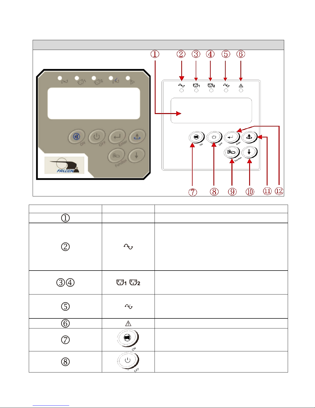
3.1.2 SC UPS< Convertible Type (Rack / Tower)> LCD Panel
6 Button LCD Panel
Item
Sign
Description
LCD Display
Green LED steadily lights up to indicate
that the utility input voltage is within the
operating window (90Vac~150Vac); the
LED flashes to indicate that the utility
input voltage is within the acceptable
window (60Vac~90Vac).
Green LED lights up to indicate there is
an output available at Programmable
Outlet 1 & Programmable Outlet 2.
Amber LED lights up to indicate the
Bypass Input is normal or continuously
blinks when UPS is in bypass mode.
UPS Fault LED
UPS On / Alarm Silence
UPS Inverter output off
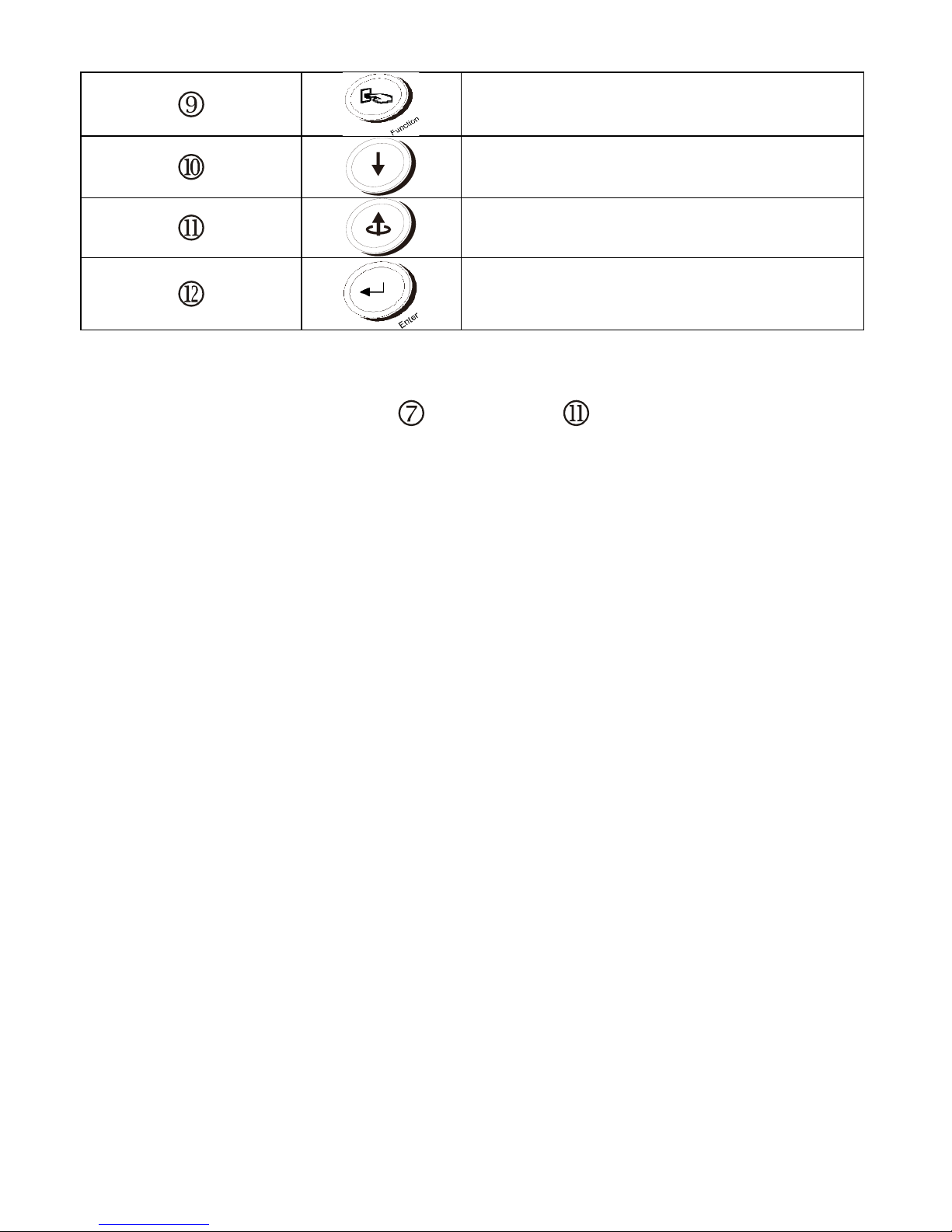
9
Special functions log in/out
Go to next page
Go to previous page or change the
setting of the UPS.
Apply UPS setting change
◎ Manual Bypass: To transfer in and out of bypass mode, verify the UPS is in
online mode, and then press " UPS On” and " Previous Page" buttons
simultaneously for approximately 3 seconds. The bypass LED and audible
alarm will activate approximately every 2 seconds indicating the UPS is in
bypass mode. Battery back-up is not available while the UPS is in bypass mode.
10
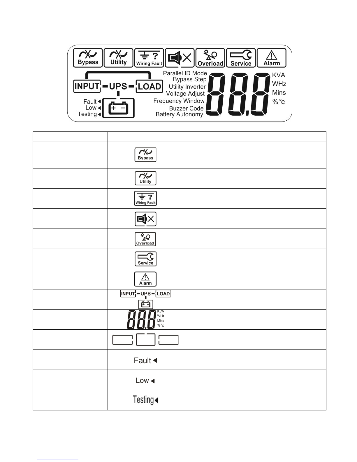
3.1.3 LCD Description
Item
Icon
Description
1
Bypass Input Abnormal, UPS fails to
transfer to bypass, Bypass Abnormal
at ECO mode
2
Utility Input Abnormal
3
Site Wiring Fault
4
Buzzer Silent
5
UPS Overload
6
Service Mode (Disabled)
7
UPS Fault Alarm
8
UPS Flow Chart
9
3-Digit Measurement Display
10
Indicates the item to be measured
11
Battery Abnormal
12
Battery Low
13
Indicates Battery Self-test
11
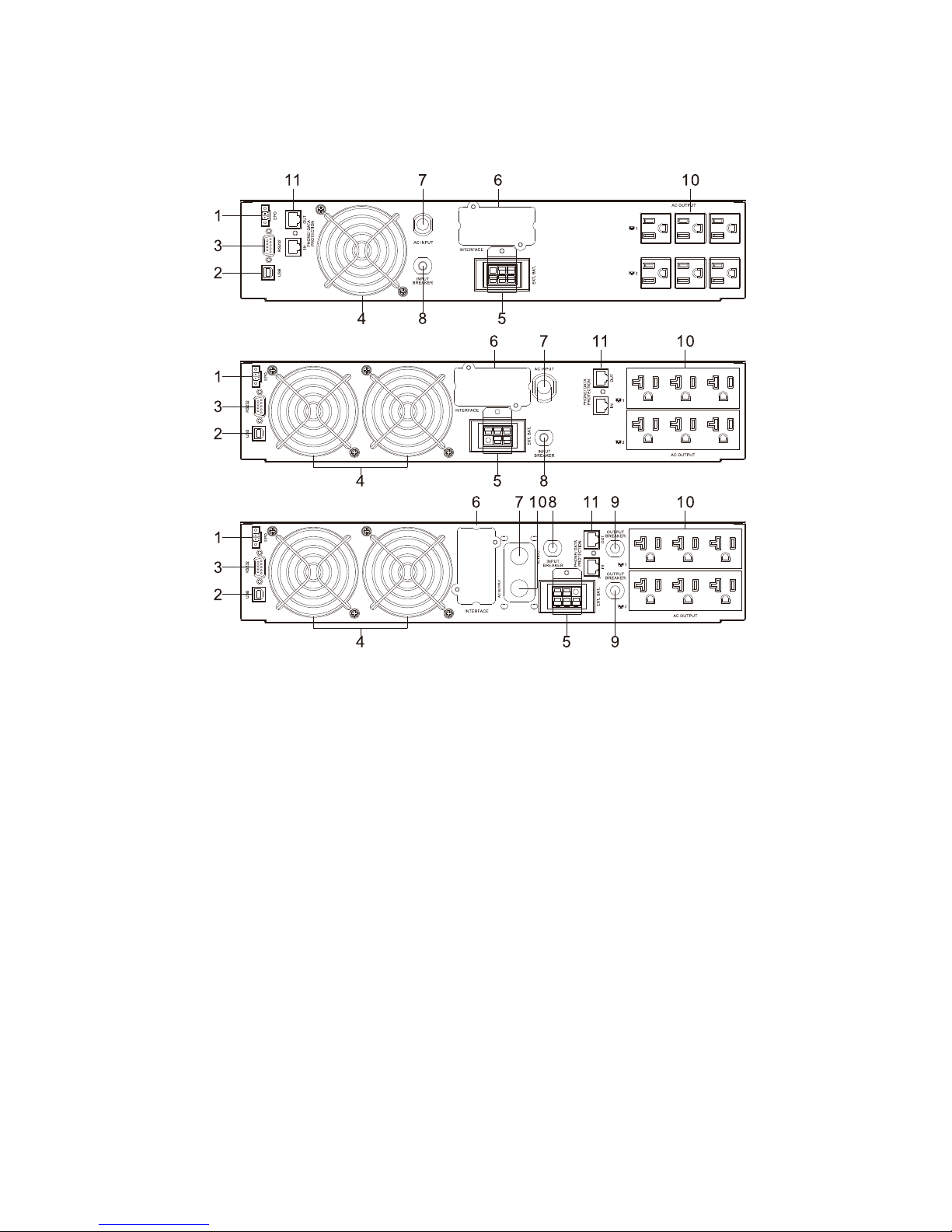
3.2 Rear Panel
SC UPS, 120Vac
1. Emergency Power Off (EPO)
2. USB port
3. RS-232 port
4. Fan
5. External battery connector
6. Slot for optional communication cards
7. AC input power line cord
8. Utility input circuit breaker
9. Output circuit breaker for 2 outlets
10. Programmable Output Receptacles
11. Communication Surge Protection
700VA
/1kVA /
1.5kVA
2kVA
3kVA
12
3.3 Communication Port
The UPS is equipped with a true RS-232 communication port to provide
communication with bundled UPS monitoring software for remote monitoring of the
UPS. In addition, there are six optional interface cards available to meet various
communication needs: USB, EPO, DCE (dry contact relay card), R2E, USE, and
an SNMP / HTTP card. (Please reference Chapter 8.) The software bundled with
the UPS is compatible with many operating systems, including Windows XP / Vista
/ 2008 / 7 / 8, Novell, NetWare, UNIX, Linux 2.6.x, Mac OS X v10.5 Leopard, and
Mac OS X v10.6 Snow Leopard. Please contact Falcon Electric for suitable
software. All communication ports including optional cards can be active and used
simultaneously to monitor the UPS status. However, only one communication
interface (the one with the highest priority) can control the UPS at a time. The
priorities of these communication interfaces are listed below (highest priority first).
1) EPO input port
2) Optional interface card
3) USB
4) RJ11/RJ45 Communication surge protection
5) RS-232
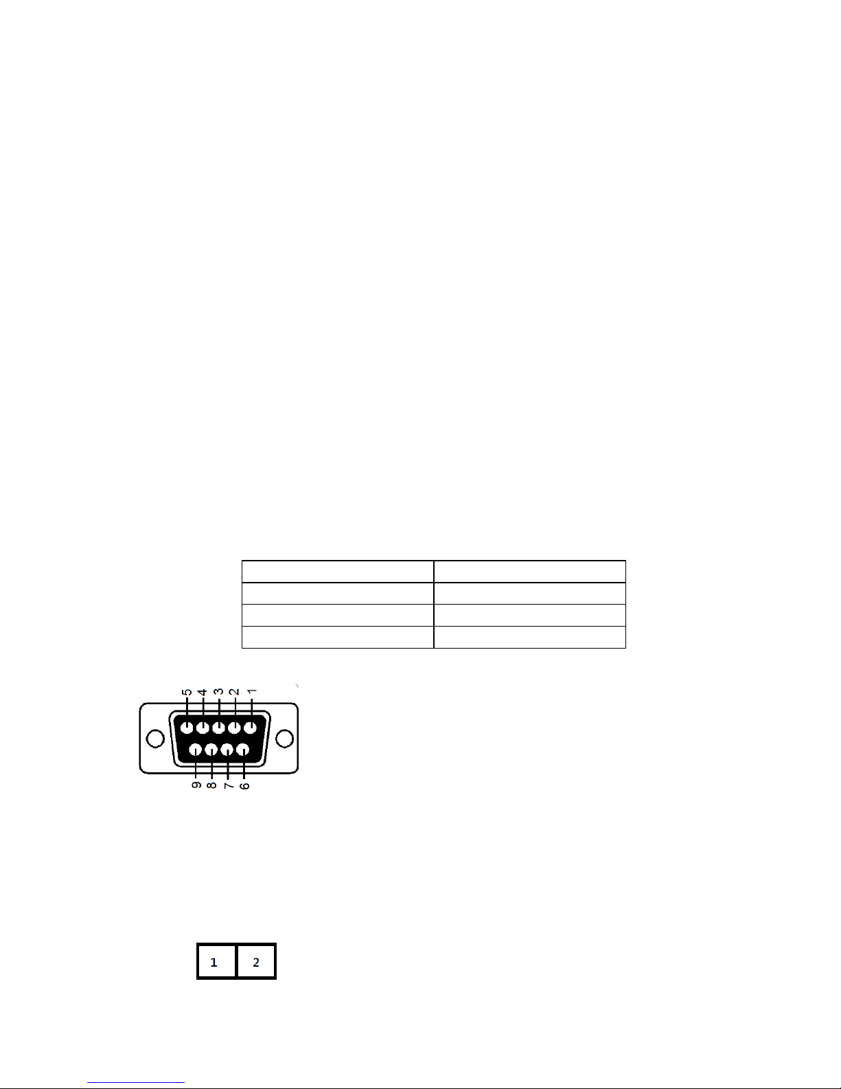
3.3.1 True RS-232
The RS-232 interface must be configured as follows:
Baud Rate
2400 bps
Data Length
8 bits
Stop Bit
1
Parity
None
Pin Assignments:
3.3.2 EPO / ROO
Pin Assignments: Short pins 1-
2 to activate remote shutdown
while on battery mode.
Pin 3: RS-232 Rx
Pin 2: RS-232 Tx
Pin 5: Ground
Function setting:
1. EPO NC Shutdown UPS
2. EPO NO Shutdown UPS (Default)
3. ROO NC Start-up UPS
4. ROO NO Start-up UPS
 Loading...