


Falcon SG2K-2T-HW, SG2K-1T-HW, SG3K-1T-HW, SG3K-2T-HW User Manual
OWNER'S
OPERATING
MANUAL
Hardwire Uninterruptible Power Supply Models:
SG2K-1T-HW
SG2K-2T-HW
SG3K-1T-HW
SG3K-2T-HW
Detailed SG Series product specifications are available in PDF format at www.falconups.com
FALCON®Electric Inc., 5106 Azusa Canyon Rd., Irwindale, California 91706, (626) 962-7770, Fax 626-962-7720, Email: sales@falconups.com
2006 Falcon®Electric Inc. All rights reserved.
All other brand names and trademarks are the property of their respective owners.
The information stated in this document is subject to change without notice. 2006-04-05
Falcon
®
, Falcon® Electric and UPS Plus logos are registered trademarks of Falcon Electric Inc
Rev. NR

SG UPS Features. ...... 1
SG Series Online UPS Block Diagram. .... 1
Important Safety Instructions (READ FIRST) .... 2
Chapter 1.
SG Series UPS Overview ..... 3
True Regenerative Online Design .... 3
Input Power Factor Correction .... 3
Microprocessor Control ..... 3
SNMP/HTTP Remote Management .... 3
Dip Switch Settings DIagrams .... 5
Chapter 2.
Installation Instructions ..... 6
UPS Input and Output Requirements. .... 6
UPS Output Requirements. ..... 7
UPS Startup ....... 8
Extended Battery Bank Interconnection. . . . 10
Extended Battery Bank Installation Procedure . . 10
Extended Battery Bank Selection Guide ...11
Chapter 3.
Operation .......12
Front Panel Indicators & Function Key Diagram . . 12
Front Panel Function Description ....12
Audible Alarms ......14
Category One Alarms .....14
Category Two Alarms .....14
Chapter 4.
Rear Panel Details ......15
SG2K-1T-HW & SG3K-1T-HW Rear Panel. . . 15
SG2K-2T-HW & SG3K-2T-HW Rear Panel . . . 15
Chapter 5.
Communications Interfaces. ....16
RS-232 Interface (DB-9) .....16
Communications Option Slot .....16
Contact Closure & Opto Interface Options ...17
Chapter 6.
Maintenance & Technical Support ....20
Care & Maintenance ......20
Battery Life vs. Temperature .....20
Battery Replacement ......20
Storing the UPS and Batteries.....21
FCC Considerations ......21
Technical Support & RMA Procedure ....22
Requesting Technical Information or Support. . . 22
FALCON Web Support ......22
Warranty ........23
Specifications ........24
TABLE OF CONTENTS
SG SERIES UPS FEATURES
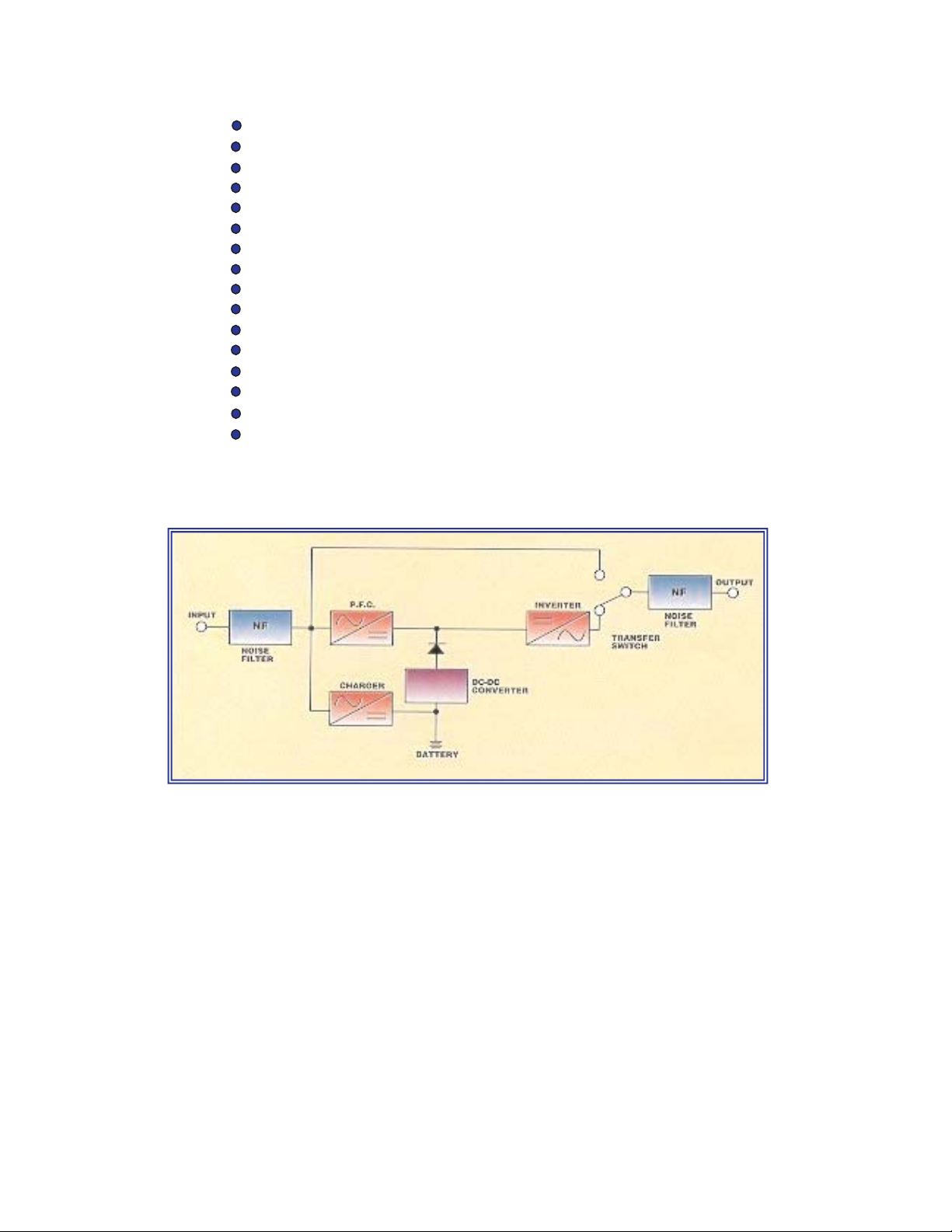
SG SERIES ON-LINE UPS SYSTEM BLOCK DIAGRAM
Hardwire Input and Output Conneciton
True Double Conversion On-Line Design
Input Power Factor Correction
Wide Input Voltage Window
Pure Sinewave Output
Precision Output Voltage Regulation
Superior Brownout, Surge and Transient Protection
Internal System Bypass
Eliminates Generator Frequency & Voltage Drift
Microprocessor Control & RS-232 Communications
UPSILON
®
Monitoring & Shutdown Software
Optional Frequency Conversion
Optional Extended Battery Packs & Chargers
Optional External Maintenance Bypass Switch
Optional Internal SNMP/HTTP Interface Card
Two-Year Warranty
1

IMPORTANT SAFETY INSTRUCTIONS
SAVE THESE INSTRUCTIONS
This manual contains important instructions which must be followed during the installation,
operation and maintenance of this UPS and its batteries. Please read all instructions before
operating this equipment and save this manual for future reference.
All of the models presented herein are designed for installation and use in a protected, temperature controlled
environment, free of contamination.
This UPS utilizes voltage that may be hazardous. Do not attempt to disassemble. This unit contains no user
replaceable parts. Refer all servicing to Falcon Electric, Inc.
THIS UPS IS NOT INTENDED TO BE USED IN CONJUNCTION WITH LIFE SUPPORT OR OPERATING
ROOM EQUIPMENT.
Always unplug this UPS and remove the UPS battery fuse prior to cleaning and never apply liquid or spray
detergent on the UPS.
Never attempt to service batteries. High voltage exists within the unit, which could cause electrical shock.
Servicing of batteries should be performed or supervised by personnel knowledgeable of batteries and the
required precautions. Keep unauthorized personnel away from batteries. When replacing the UPS batteries,
use the same number and type of batteries.
Allow at least 24 hours, after the UPS is first installed and turned on, to fully charge the internal battery and
assure the maximum backup time is available.
DO NOT plug this UPS into its own output as this may damage the UPS. NEVER CONNECT equipment that
could overload the UPS or demand half-wave rectification from the UPS, for example: electric drills, vacuum
cleaners or hair dryers. Never connect surge protected plug strips to the UPS output.
DO NOT remove or unplug the input cord when the UPS is turned on. This removes the safety ground from
the UPS and the equipment connected to the UPS.
This UPS contains its own energy source (batteries). The output receptacles may carry live voltage
even when the UPS is not connected
to an AC source.
Should any SG Series UPS units be stored for more than two weeks, it is mandatory that the
battery
fuse be removed prior to storage or battery
damage will result.
CAUTION
CAUTION
CAUTION
CAUTION
CAUTION
IMPORTANT
DO NOT
CAUTION
CAUTION
IMPORTANT
2

CHAPTER
CHAPTER11
SG Series UPS - Overview
General - Common for all models
1. Verify the following is included in the UPS shipping carton:
(1) UPS, (1) Software Diskette(s) & Manual, (1) Owners Manual & (1) UPS/Computer
Cable.
2. Verify the UPS unit is configured for the proper input/output voltage and frequency. This
information is stated on the nameplate label located on the rear or the side panel of the
unit. If any special input plug and output receptacle configurations were specified at the
time of order, verify for proper configuration.
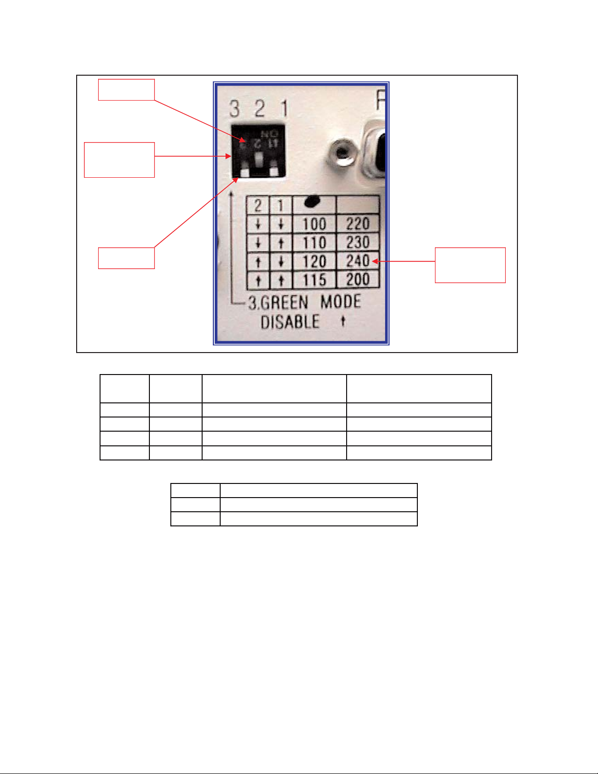
3. Set the output voltage and green mode switches located on the UPS rear panel for the
nominal UPS output voltage desired. See the switch setting tables located on
page 5.
In most cases the nominal UPS output voltage should be set to match the incoming utility
voltage. This will assure a close matching voltage in the event the UPS is placed on
bypass. NOTE: Disregard the "ON" marking on the side of the actual dip switch
housing; use the tables in this manual or the silkscreen on the UPS rear panel only.
Dip switch 3 "enables" or "disables” the "Green Mode" function. The UPS is shipped
from the factory with the switch set in the "disabled" position (up). If SW3 is switched
down or to the "enabled" position, the Green Mode function is activated. When the
load connected to the output of the UPS drops to under 10% of the full rated UPS output
for 30 seconds, the UPS is automatically placed into bypass and the inverter is turned off.
NO BATTERY BACKUP IS PROVIDED AFTER THE GREEN MODE HAS ACTIVATED.
Dip switch settings must be made while the UPS is turned off. Any changes made while
the UPS is turned on will not take effect until the UPS is turn off and back on again since
the switch settings are read by the microprocessor only during initial UPS power up
.
4. To prevent accelerated battery discharge during shipment, this UPS was shipped with the
battery circuit breaker turned off. TURN THE BATTERY DISCONNECT CIRCUIT
BREAKER ON PRIOR TO TURNING ON THE UPS INPUT CIRCUIT BREAKER.
NEVER TURN THE BATTERY CIRCUIT BREAKER OFF WHILE THE UPS AC CIRCUIT
BREAKER IS TURNED ON AND OPERATING FROM THE UTILITY VOLTAGE, OR UPS
DAMAGE MAY RESULT. UPS MUST BE COMPLETELY SHUT DOWN PRIOR TO
DISABLING THE INTERNAL BATTERY SUPPLY.
In the event this UPS is to be turned off or stored for more than two weeks, the battery
circuit breaker must be turned to the off position to prevent battery discharge. If placed in
long-term storage, every four months the UPS must be plugged in and turned on for 24
hours to allow the batteries to recharge and prevent battery damage. Failure to follow
these procedures will invalidate your warranty.
3

5. Select a suitable location for the UPS.
VERIFY THE FLOOR OR SURFACE SUPPORTING THE UPS WILL SUPPORT THE
WEIGHT OF THE UPS AND ANY OPTIONAL EXTENDED BATTERY BANKS.
SG2K-2T-HW & SG2K-2T-HW UPS MODELS = 68.4 lbs. (31 kg)
SG3K-2T-HW & SG3K-2-HW UPS MODELS = 81.4 lbs. (37 kg)
6. If unattended computer shutdown and monitoring are desired, connect the green
UPS/Computer cable to the DB-9 connector located on the UPS rear panel. Then
install the shutdown and monitoring software provided with the UPS. For your
reference, UNIX shutdown and monitoring software is available from Falcon Electric
at an additional cost.
7. Verify the location selected has adequate ventilation to allow for the proper cooling of
the UPS.
DO NOT BLOCK UPS FANS OR AIR VENTS. THE UPS MUST NOT BE
INSTALLED IN AN ENCLOSED AREA.
4
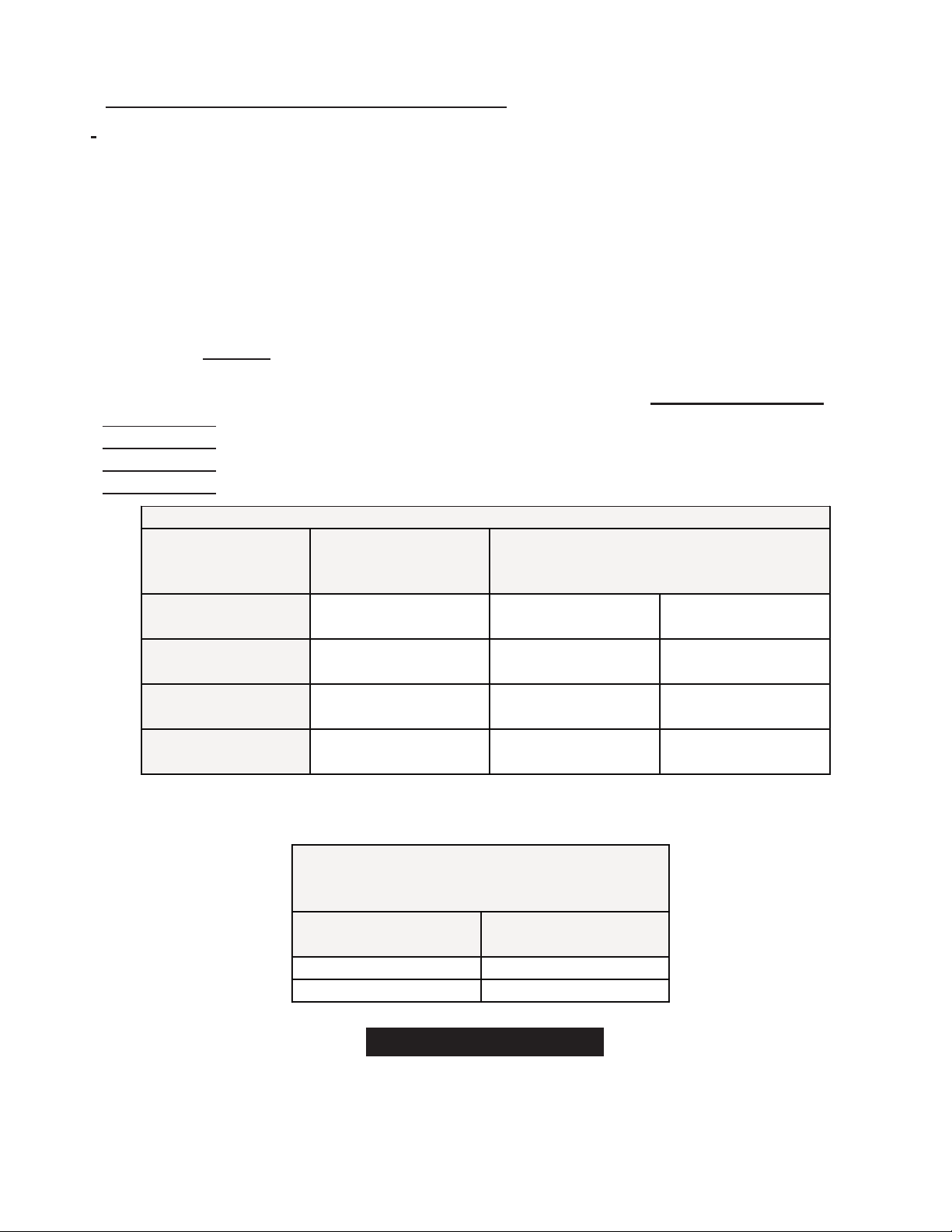
DIP
SWITCHES
SELECTION
TABLE
ON = 1
OFF = 0
SW2
SW1
OUTPUT VOLTAGE 1
(All models)
OUTPUT VOLTAGE 2
(-TX & -TXC models only)
Down
Down
208 Vac
115 Vac
Down
Up
220 Vac (default)
120 Vac
Up
Down
230 Vac
125 Vac
Up
Up
240 Vac
130 Vac
SW3
FUNCTION
Down
GREEN MODE ON
Up
GREEN MODE OFF
SWITCH SETTINGS FOR ALL MODELS
GREEN MODE SWITCH SETTINGS FOR ALL MODELS
VIEW OF OUTPUT VOLTAGE & GREEN MODE SELECT SWITCHES
(LOCATED ON THE UPS REAR PANEL)
5
1.0 UPS Input & Output Requirements.
Note: All SG Series hardwire UPS models must be installed by a licensed
electrician, in accordance with the National Electrical Code (NEC) ANSI/NFPA70
and all local regulations. It is further required that the input of SG Series hardwire
UPS be wired to a building service panel incorporating a dedicated “branch
rated” circuit breaker of the proper rating.
MODEL
REQUIRED
BRANCH RATED
CIRCUIT BREAKER
SG2K-1T-HW:- 120Vac, 50/60Hz, 14.2A, 1 phase, 2 wire plus ground 20A
SG2K-2T
-HW - 208-240Vac, 50/60Hz, 7.4A, 1 phase, 2 wire plus ground 15A
SG3K-1T-HW - 120Vac, 50/60Hz, 21.4A, 1 phase, 2 wire plus ground 30A
SG3K-2T
-HW - 208-240Vac, 50/60Hz, 11.2A, 1 phase, 2 wire plus ground 20A
WIRE GAUGE CHART
MODEL
AC INPUT
-1 = 120 Vac
-2 = 208-240 Vac
AC OUTPUT(S)
120 Vac 208 -240 Vac
SG2K-1T-HW
10 Awg. 600V
75°C CU
10 Awg. 600V
75°C CU
N/A
SG2K-2T-HW
12 Awg. 600V
75°C CU
N/A
12 Awg. 600V
75°C CU
SG3K-1T-HW
10 Awg. 600V 75°C
CU
10 Awg. 600V
75°C CU
SG3K-2T-HW
12 Awg. 600V
75°C CU
12 Awg. 600V
75°C CU
SCREW TORQUE SPECIFICATIONS FOR
INPUT/OUTPUT WIRING BLOCK
UPS
Wire Gauge
Torque
(inch pounds)
18 - 10 Awg.
20
8-6 Awg
25 - 30
ONLY USE WIRE WITH SOLID COPPER CONDUCTORS FOR ALL INPUT/OUTPUT/BATTERY WIRING
CAUTION
To reduce the risk of fire, connect only to a circuit providing over-current protection incorporating the
specified "branch rated" over-current protection device in accordance with the National Electrical
Code, ANSI/NFPA 70.
CHAPTER
CHAPTER22
Installation Instructions For Hardwire Models
6