

Falcon CT1090, SE900, SE1000, SE1092 Nstallation, Operation & Maintenance Instructions
Contemporary Falcon Cooker Hoods
Revision: 02/02/2009 1
ENGLISH
2
Installation, Operation
& Maintenance
Instructions
FRANÇAIS
4
Guide d’Installation,
D’Utilisation et
Conseils d’Entretien
NEDERLANDS
8
Instructies voor
montage, gebruik
en onderhoud
CT900
CT1090
Contemporary Falcon Cooker Hoods
Contemporain Hottes Falcon
Moderne Falcon - Dunstabzugshauben
Eigentijds Falcon Afzuigkappen
Modern Falcon Kåpor
DEUTSCHE
6
Montage-,
Gebrauchs- &
Wartungsanleitung
SVENSK
10
Installations-,
danvändnings-
och underhållsanvisningar
Clarence Street, Royal leamington Spa,
Warwickshire, CV31 2AD, England.
Tel: +44 (0) 1926 457400
Fax: +44 (0) 1926 450526
E-mail: Consumers@falconappliances.co.uk
www.falconappliances.co.uk
Falcon is a business name of AGA RANGEMASTER GROUP PLC
Contemporary Falcon Cooker Hoods
Revision: 02/02/2009 2
Installation, Operation & Maintenance Instructions
SECTION 1 INTRODUCTION 2
SECTION 2 EXTRACTION PERFORMANCE 2
SECTION 3 IMPORTANT INFORMATION 2
SECTION 4 INSTALLATION 2
4.1 Removing Grease Filters
4.2 Blower Exhaust Position
4.3 Duct Installation
4.4 Fixing the Hood to the Wall
4.5 Connecting the Ducting
4.6 Electrical Installation
SECTION 5 OPERATING INSTRUCTIONS 3
SECTION 6 MAINTENANCE 3
SECTION 7 SPECIFICATIONS 3
FIGURE 1: DIMENSIONS AND FIXING DETAILS 3
SECTION 1. INTRODUCTION
Your range cooker is a semi-professional unit which gives you the power and flexibility to
realise your full potential in the kitchen. Inevitably, during the cooking process, there will
be heat, vapours and fumes produced. Your Falcon extractor has been designed to
complement the range cooker both in looks and performance in order to create the ideal
environment for creative cooking.
SECTION 2. EXTRACTION PERFORMANCE
The most important influence on the performance of the extractor is the design of the
ducting which takes the exhaust air from the extractor to the outside wall louvre. The duct
route should be a prime consideration during the initial stages of the kitchen design.
Please note the following:
The extractor is provided with a spigot suitable for connecting 150mm diameter
duct.
Note: 150mm is the minimum duct diameter consistent with efficient extraction.
The exhaust duct route length should be kept as short as possible with as few
bends as possible.
The most efficient configuration is to duct straight through an outside wall so try to
position the cooker against an outside wall when designing your kitchen layout.
The hood can be vented either to the top exhaust or the rear exhaust position. Use
the position which gives the shortest duct route length and least number of bends.
(The blower will need to be rotated for ducting directly through the rear exhaust
position.)
A route with more than two 90 bends will significantly degrade the performance of
the extraction system. If possible, avoid having a 90 bend at the extractor exhaust
spigot; keep bend radii as large as possible to maintain a smooth airflow without
vortices; avoid kinks in flexible ducting; pull flexible ducting taut over straight runs to
ensure that the internal surface is as smooth as possible.
SECTION 3. IMPORTANT INFORMATION
The following minimum headroom is required to accommodate the cooker and hood:
For a small charge customised replacement chimneys can be produced to suit your
requirements.
The minimum distance between the range hob burners and the bottom of the extractor is
essential to prevent overheating of the extractor and its components.
If you are fitting a Falcon splashback then the cooker-to-hood clearance is dictated by the
splashback height of 800mm excluding flanges.
Please also note that a 90 bend in the flexible ducting will require 215mm minimum headroom to give a smooth radius with no kinking.
Requirements of the relevant authorities concerning the discharge of exhaust air must be
complied with.
Attention:
This appliance requires an earth connection.
Ensure that the supply voltage corresponds to that marked on the rating label inside the
extractor.
The extractor must be isolated from the electrical supply before carrying out any cleaning
or maintenance operations.
Pay particular attention to fire risk when frying. To minimise the risk of fire, all
instructions relating to cleaning the grease filters and removing grease deposits
must be adhered to.
Do not flambé under the extractor.
SECTION 4. INSTALLATION
4.1 Removing the Grease Filter(s)
Place extractor on its backplate on a horizontal surface.
To remove the grease filters pull/lift the filter release lever away from the hood base. This
releases the retaining clips allowing the filter to be carefully lifted away from the hood.
Take care not to scratch the hood.
The four internal fixing holes, blower assembly and spigot blanking plate can now be
accessed through the openings in the baseplate. (See Figure 1).
4.2 Blower Exhaust Position
The hood can be vented either to the top exhaust or the rear exhaust position. Each
exhaust position has 4 studs onto which can be bolted either the blower assembly or a
blanking plate.
Bolt blower assembly to chosen exhaust position and the blanking plate to the unused
position.
When changing the exhaust position, care should be taken not to excessively pull or twist
the cable attached to the blower.
4.3 Duct Installation
Make a hole in the wall or ceiling to take the 150mm diameter ducting from the extractor
exhaust spigot to the outside.
The exhaust duct route length should be kept as short as possible with as few bends as
possible - see Section 2.
Knock a hole in the outside wall to match the internal measurements of the louvre.
4.4 Fixing the Hood to the Wall
If you are fitting a Falcon Splashback it must be fitted before the hood.
Full instructions for mounting the hood are given in Figure 1.
Note: The decorative chimney can be removed to ease handling of the hood.
The supporting wall must be of good quality, have an even surface and be sturdy enough
to support the extractor.
Fixings must be used which are suitable for the type of wall construction.
4.5 Connecting the Ducting
Connect ducting to extractor exhaust spigot. This may have to be done prior to fixing the
extractor to the wall. You may find this easier with the chimney removed. The chimney is
attached using M4 machine screws which can be accessed through the filter opening(s).
When the extractor is in position, check that the duct has not been flattened or kinked
along its route.
Connect the ducting to the wall louvre spigot or alternative outside termination.
Secure the louvre to the outside wall. Ensure that any air fins are directed downwards.
Refit the grease filter(s).
4.6 Electrical Installation
The extractor is a stationary appliance designed to be connected by fixed wiring to the
electrical supply. A competent electrical technician must perform the electrical installation.
The extractor must be fed from a 230Vac single phase electrical supply using a switched
spur fitted with a 3A fuse. The spur should be located adjacent to the extractor/cooker so
that the supply can be disconnected from the extractor using the switch. The means of
disconnecting from the supply must have a minimum contact separation of 3mm in all
poles. Alternatively a means of disconnection in the fixed wiring according to the relevant
wiring rules must be fitted.
A supply cord for connecting the spur to the extractor is included.
The mains supply is connected to the free end of this cord as follows:
Cooker-to-hood clearance (min): 800 mm
Hood height including chimney: 550—950 mm
Minimum ceiling height with standard chimney: 2290mm
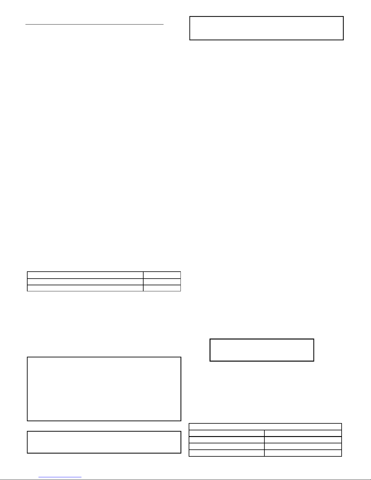
INCOMING SUPPLY CORD CONNECTIONS
Core Core Colour
Live Brown
Neutral Blue
Protective Earth Green/Yellow
The exhaust air must not be discharged into a flue which is used for exhausting
fumes from appliances supplied with energy other than electricity, e.g. oil or gasfired central heating boilers, gas-fired water heaters, etc.
Adequate ventilation of the room must be provided when the cooker, extractor and
appliances supplied with energy other than electricity (e.g. gas-fired or oil-fired heaters, etc.) are used simultaneously. The room must be provided with vents to allow a
constant flow of fresh air.
Warning
Proper care must be taken to ensure that the negative pressures caused by high
performance extraction systems do not adversely affect the safe operation of certain
types of fuel-burning appliances (gas, oil or solid fuel), including those installed in
the kitchen and possibly also those installed in other parts of the house.
Where such fuel-burning appliances are installed, adequate ventilation MUST be
provided in the room of installation, located and sized such that the negative pressure in the room created by the extractor does not exceed 4Pa.
In case of doubt, do not operate the extractor and fuel-burning appliance(s) simulta-
neously and consult an appropriate (for the fuel type) expert for advice.
ELECTRICAL HAZARD
DISCONNECT ELECTRICAL SUPPLY
BEFORE PROCEEDING FURTHER
Contemporary Falcon Cooker Hoods
Revision: 02/02/2009 3
SECTION 5. OPERATING INSTRUCTIONS
a. Switch power on at the fused spur.
b. The extractor has 6 push-buttons which illuminate when selected. Their functions
are summarised in the table below.
c. The extractor controller will automatically switch off the appliance if there has been
no operator action for 4 hours.
d. After 30 hours accumulated running GREASE FILTER SATURATION will be sig-
nalled by all 6 indicators flashing. Reset by pressing Push-button FAN OFF (delay).
SECTION 6. MAINTENANCE
Regular maintenance is essential to ensure good performance and long-life.
To clean the stainless steel surfaces of the extractor use a proprietary cleaning agent. Do
not use abrasive cleaning materials or products.
Clean the grease filters in a dishwasher or by hand-washing in hot water and detergent.
Wash the filters at least every 2 months - sooner if the extractor is used extensively.
To remove the grease filters pull the chrome effect filter release lever away from the hood
base. This releases the retaining clips allowing the filter to be carefully lifted away from
the hood. Care should be taken not to scratch the hood.
To maintain the immaculate appearance of the extractor, and to minimise fire risk, ensure
that grease deposits on the extractor surfaces are kept to a minimum by regular cleaning.
To access the halogen lamps for replacement lever off the chrome ring immediately
surrounding the matt glass with a screwdriver. Only replace with bulbs of the same type
and rating.
SECTION 7. SPECIFICATIONS
Hood weights:
Blower airflow, nominal: 1,000 m3/hr
Noise level: 56dBA
Supply voltage: 230V~ 50Hz
Halogen lamp voltage: 12V
Blower power input: 1 @ 300W
Halogen lamp power: 2 x 20W
Total power: 340W
Fuse size for electrical supply: 3A
Blower spigot diameter: 150mm
CT900 26Kg
CT1092 29Kg
Pushbutton Function
LIGHTS ON/OFF
0 1
FAN ON SPEED 1 (min);
FAN OFF (immediate stop).
2 FAN ON SPEED 2
3 FAN ON SPEED 3
4 FAN ON SPEED 4 (max)
FAN OFF AFTER 10 MINUTE DELAY to clear residual
fumes; indicator flashes during time-out.
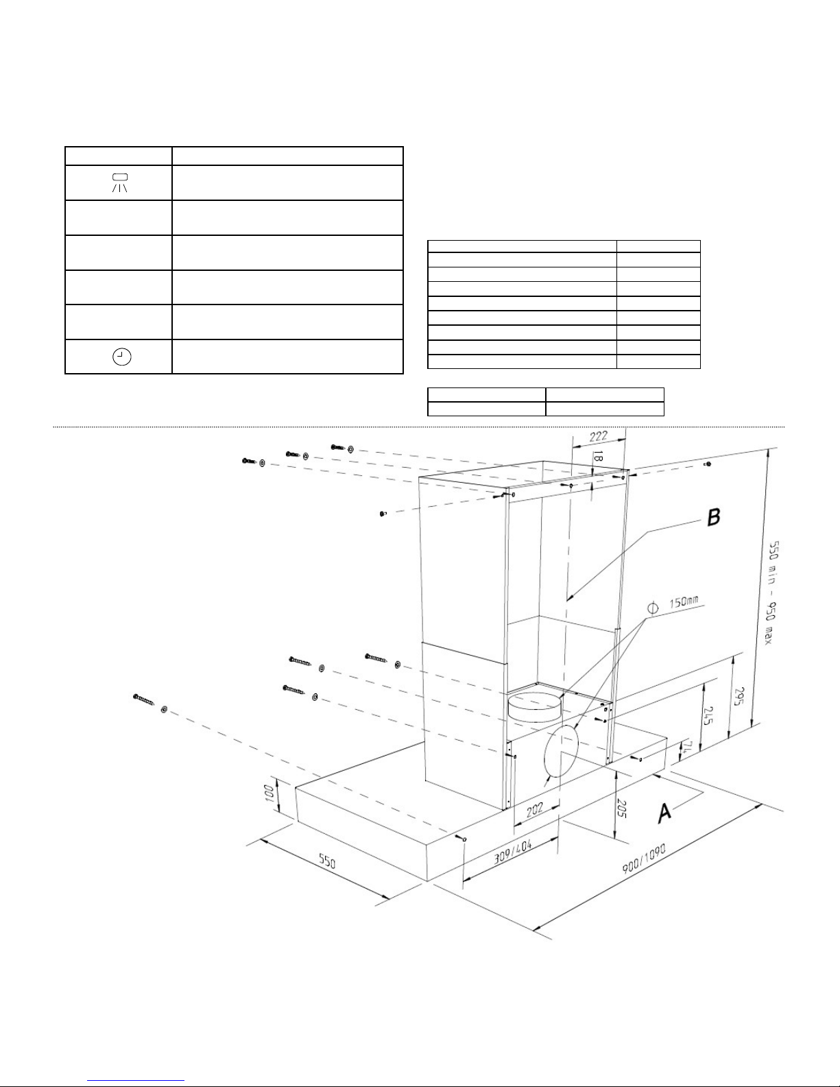
FIGURE 1
HOOD DIMENSIONS
And
FIXING HOLE DETAILS
Method 1
1. Mark a horizontal line (A) in the position of the hoods bottom edge - if you have
already fitted a splashback then the top edge of this will serve.
2. Mark a vertical centre line of the range cooker and the hood (B).
3. Mark the positions of at least four fixing hole centres, as shown above.
4. If using the rear exhaust spigot position, mark and knock out a hole suitable to
accommodate 150mm dia. ducting as detailed in the installation manual.
5. Remove the grease filters to gain access the internal fixing holes and the chimney
to access the external fixing holes (if using).
6. Secure hood using fixings suitable for the wall construction in the previously marked
positions.
Method 2
1. Remove the grease filters to gain access the internal fixing holes in the hood rear.
2. If using the rear exhaust spigot position, mark and knock out a hole suitable to
accommodate 150mm dia. ducting as detailed in the installation manual.
3. Offer the hood up to the wall in the desired position and mark the wall through the
fixing holes in the hood rear. This is a 2 person job.
4. Secure hood using fixings suitable for the wall construction in the previously
marked positions.
Contemporain Hottes Falcon
Revision: 02/02/2009 4
GUIDE d’Installation,D’Utilisation et Conseils d’Entretien
SECTION 1 INTRODUCTION 4
SECTION 2 PERFORMANCE DE L’EXTRACTION 4
SECTION 3 RENSEIGNEMENTS IMPORTANTS 4
SECTION 4 INSTALLATION 4
4.1 Sortir les filtres à graisse
4.2 Situation de l’échappement du ventilateur
4.3 Installation de la conduite
4.4 Comment attacher la hotte conte le mur
4.5 Comment raccorder la conduite
4.6 Installation électrique
SECTION 5 INSTRUCTIONS D’UTILISATION 5
SECTION 6 MAINTIEN 5
SECTION 7 SPECIFICATIONS 5
DESSIN 1: DIMENSIONS ET DÉTAILS FIXATION 5
SECTION 1. INTRODUCTION
L’élément le plus important pour une bonne performance de la hotte est le conduit qui
évacue l’air vers l’extérieur.Ce conduit doit etre une priorité dès le début de la conception
de votre cuisine.
SECTION 2. PERFORMANCE DE L’EXTRACTION
L’élément le plus important pour une bonne performance de la hotte est le conduit qui
évacue l’air vers l’extérieur.Ce conduit doit etre une priorité dès le début de la conception
de votre cuisine.
Veuillez noter les éléments suivants :
La hotte est fournie avec un adaptateur approprié à fixer au conduit de 150mm de
diamètre.
A noter: 150mm est le dimètre minimum du conduit permettant une extraction effica-
ce.
La longeur du conduit d’extraction doit être aussi limiteé que possible avec le moins
de coudes possible.
La configuration la plus efficace est d’évacuer directement par un mur extérieur.
Ainsi il est conseillé de placer le fourneau contre un mur extérieur quand on conçoit
le plan de la cuisine.
On peut faire évacuer la fumée par l’orifice supérieur ou par l’orifice arrière. La
turbine de ventilation devra être pivoté pour la position d’évacuation par l’arrière.
Un conduit avec plus de 2 coudes a 90° dégradera d’une façon significative la per-
formance du système d’extraction. Si possible évitez d’avoir un coude de 90° à la
sortie, utilisez des coudes dont les diametres sont aussi grands que possibles pour
maintenir un flux d’air continu sans tourbillonnements; évitez des entortillements
des conduits flexibles; étirez le conduit flexible pour s’assurer que la surface interne
soit aussi lisse que possible.
SECTION 3. IMPORTANT INFORMATION
Pour une petite charge des cheminées adaptées aux besoins du client de rechange
peuvent être produites.
La distance minimum enter les brûleurs de la plaque du forneau et le bas de la hotte est
essentielle pour empêcher la surchauffe de la hotte et de ses pièces.
Si vous voulez protéger le mur entre le fourneau et la hotte avec une credence Falcon
veuillez bien noter la hauteur minimum de 800mm du tableau ci-dessus.
En cas d’un coude à 90° du conduit il faut respecter un encombrement minimum de
215mm. Cela permettra de courber le conduit sans faire de faux-pli.
Il faut respecter les normes en vigueur concernant le rejet de l’air.
Attention:
Cet appareil doit être mis à la masse. Assurez-vous que le voltage d’alimentation corres-
pond à celui marqué sur l’etiquette de classement à l’interieur de la hotte.
La hotte devra être mise hors tension avant de faire des opérations de nettoyage ou
d’entretien.
Il faut absolument faire attention au risque du feu quand l’on est en train de frire. Pour
minimiser le risque de feu, tous les conseils concernant le nettoyage des filtres à graisse
doivent être respectés.
Ne pas approcher de flamme sous la hotte.
SECTION 4. INSTALLATION
4.1 Démontage des filtres à graisse
Mettez la plaque arrière sur une surface horizontale.
Pour enlever les filtres à graisse, tirez le levier de filtre et retirez le filtre.
Les quatre trous de fixation interne, le ventilateur et la plaque d’obturation sont accessi-
bles par les trous dans la plaque arrière. (dessin 1).
4.2 Position du ventilateur.
La hotte peut être ventileé soit par la position d’échappement supérieur soit pas la posi-
tion d’échappement arrière. Chaque position d’échappement a quatre goujons auxquels
on peut positionner soit le montage ventilateur soit une plaque.
Positionner le ventilateur à la position d’échappement désirée et la plaque à la position
non utilisée.
En changeant la position d’échappement il faut faire attention de ne pas tirer ou entortiller
excessivement le cable électrique d’alimentation du ventilateur
4.3 Installation du conduit
Faites un trou dans le mur ou le plafond par lequel on peut faire passer le conduit de
150mm de diamètre de la hotte à l’extérieur.
La longueur du conduit devra être limitée au plus court possible avec le moins de coudes
possible – voir section 2.
Faites un trou dans le mur extérieur correspondant aux mesures internes de la grille de
ventilation.
4.4 Comment fixer la hotte contre le mur
Si vous fixez une credence Falcon elle doit être installée avant la hotte.
Des instructions complètes pour monter la hotte sont données (dessin 1).
A noter: La partie décorative de la hotte peut être enlevée pour faciliter la manoeuvre de
la hotte.
Le mur recevant l’appareil devra être de bonne qualité avec une surface plane et être
suffisamment solide pour supporter la hotte.
Les fixations appropriées à la nature de la construction du mur devront être utilisées.
4.5 Comment raccorder le conduit
Fixez le conduit à l’adaptateur. Il se peut qu’on soit obligé de le faire avant de fixer le
ventilateur contre le mur. Il est conseillé d’ enlever la partie décorative avant cette man-
œuvre. La cheminée est attachée en utilisant des vis machine M4 qui peuvent être accé-
dés par la/les ouverture(s) à filtre.
Quand le ventilateur est en place, vérifiez que le conduit ne soit pas aplati ou entortillé
sur son parcours.
Raccordez le conduit à la grille de ventilation du mur ou à une terminaison extérieure
alternative.
Fixez bien la grille de ventilation au mur extérieur. Assurez-vous que les ailettes se
dirigent vers le bas.
Remplacez les filtre(s) à graisse.
4.6 Installation électrique
L’extracteur est un appareil fixe destiné à être branché au secteur par installation électri-
que fixe. Un technicien électricien compétent doit realises l’installation électrique.
Le ventilateur devra être alimenté avec une prise comprenant un fusible de 3A en mono-
phasé 230V. L’interrupteur devra étre situé à coté du ventilateur/fourneau pour que le
courant puisse être coupé du ventilateur. Le fusible devra avoir un contact minimum de
séparation de 3mm entre tous ses pôles. Si non un moyen different de couper l’installa-
tion électique doit être prévu et conforme au règlement électrique en vigueur.
Un câble pour relier la prise au ventilateur est inclu.
L’évacuation peut se faire dans un conduit existant à condition que les fluides
de ce conduit soient produits exclusivement par des appareils électriques. Sont
exclus les conduits de chauffage central, de chauffe-eau à gaz ou à fioul etc.
Il faut veiller à avoir une ventilation adéquate de la pièce quand la hotte du
fourneau et les appareils à énergie autre que l’électricité (e chauffe-eau à gaz
ou à fioul etc) sont en marche simultanément. La pièce doit être pourvue
d’orifices pour permettre une arrivée d’air frais constante.
Attention!
Il faut bien veiller à ce que le système d’ extraction de haute performance n’affecte pas
le bon fonctionnement des autres appareils à combustibles (gaz, fioul, etc...) qu’ils
soient dans la cuisine ou dans d’autres parties de la maison.
Là où sont installés ces appareils à combustibles, IL FAUT prévoir une ventilation
adéquate qui prend en compte la capacité d’extraction dela hotte falcon.L’ écart entre
la ventilation et l’extraction par la hotte ne doit pas excéder 4Pa.
En cas de doute ne faites pas functionner la hotte et l’appareil à combustible simulta-
nément et consultez un expert (du combustible) approprié pour vous bien conseiller.
Dégagement minimum entre le fourneau et la hotte: 800mm
Hauteur de la hotte y compris cheminée: 550—950 mm
Hauteur requise du plafond avec cheminée standard:
2290mm
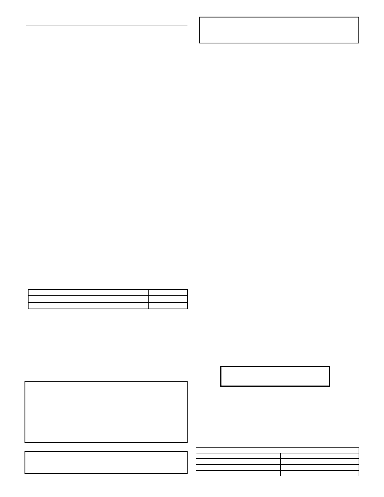
CODE CONNECTION COULEURS DES DIFFÉRENTS FILS
Faisceau Couleur de faisceau
Conducteur Marron
Neutre Bleu
Terre Vert/Jaune
ÉLECTRICITÉ=DANGER
COUPEZ L’ÉLECTRICITÉ AVANT DE CONTINUER
 Loading...