

Page 1
VER A0
Manual Instruction
1
2
6
6
7
11
11
CATALOGUE
Features
Names of each part and functions
Operation Instructions
Wiring
Installation illustration
How to clear the usual faults
Specification
Page 2
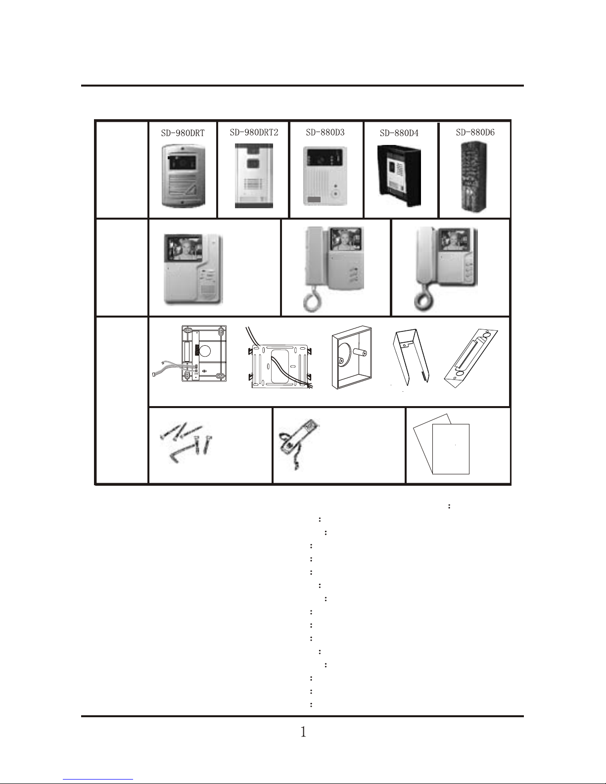
Features:
SD-920R1S
Inter-
phone
Door
phone
Manual
Other
Accessaries
S
D
-
9
2
0
R
1
S
S
D
-
8
8
0
R
2
S
S
D
-
8
8
0
R
3
S
V
E
R
A
1
.
0
M
a
n
u
a
l
I
n
s
t
r
u
c
t
i
o
n
S
D
-88
0
R
1
2
M
a
n
u
a
l
in
s
tr
u
c
ti
o
n
VERA1
.0
S
D
-88
0
R
1
2
A
SD-920R1S
SD-880R2S
SD-880R3S
VER A1.0
Manual Instruction
Indoor station and outdoor station can match into many kits
SD-920R1S and SD-980DRT match SD-920R1S-1
SD-920R1S and SD-980DRT2 match SD-920R1S-2
SD-920R1S and SD-980D3 match SD-920R1S-3
SD-920R1S and SD-880D4 match SD-920R1S-4
SD-920R1S and SD-880D6 match SD-920R1S-6
SD-880R2S and SD-980DRT match SD-880R2S-1
SD-880R2S and SD-980DRT2 match SD-880R2S-2
SD-880R2S and SD-880D3 match SD-880R2S-3
SD-880R2S and SD-880D4 match SD-880R2S-4
SD-880R2S and SD-880D6 match SD-880R2S-6
SD-880R3S and SD-980DRT match SD-880R3S-1
SD-880R3S and SD-980DRT2 match SD-880R3S-2
SD-880R3S and SD-880D3 match SD-880R3S-3
SD-880R3S and SD-880D4 match SD-880R3S-4
SD-880R3S and SD-880D6 match SD-880R3S-6
R
1
R
2
R
3
R
4
L
+
L-
Screws and driver
Bracket Bracket
Embeded Box
Handset and spring wire
Rain cover
Corner
SD-880R2S
SD-880R3S
Page 3

Names of each part and functions
Door station SD-980DRTDoor station SD-980DRT
Infrared LEDs
Let you see
clearly even
at night.
Speaker
Broadcast the
voice from the host
Microphone
Pick up the voice
of the visitor.
Camera
Pick up the image of
the visitor clearly.
Fore view
Call button
Chime "ding dong"
sound can be heard
from inter-phone,when
the button is pressed,
the camera works
simultaneously.
Terminals function:
R1--video output
R2--ground
R3--audio signal
R4--DC 13V 15V input
Rear view
Infrared LEDs let
you see clearly in
the night even
without any light
Chime "ding
dong" sound
can be heard
and adjusted.
Clear & bright
pictures based
on our high
technology.
With perfect design
and sensitive operation.
Inner-calling be
available when
several inter-phones
within one system
Door station SD-980DRT2Door station SD-980DRT2
Camera
Pick up the image of
the visitor clearly.
Microphone
Pick up the voice
of the visitor.
Fore view
Infrared LEDs
Let you see clearly
even at night.
Speaker
Broadcast the
voice from the host
Call button
Chime "ding dong" sound
can be heard from interphone,when the button is
pressed,the camera works
simultaneously.
Terminals function
R1--video output
R2--ground
R3--audio signal
R4--DC 13V 15V input
Rear view
Page 4

4P LINE FUNCTION DESCRIPTION:
WHITE AUDIO
BLACK GND
RED VCC
BROWN VIDEO
4P LINE
SPEAKER VOLUME
MICROPHONE SENSITIVE
Rear view
Call button
Chime "ding dong" sound
can be heard from inter-phone,
when the button is pressed,
thecamera works simultaneously.
Microphone
Pick up the voice
of the visitor.
SCREW
SCREW
Fore view
Speaker Broadcast
the voice from the host
Camera
Pick up the image
of the visitor clearly.
Door station SD-880D6Door station SD-880D6
Door station SD-880D4Door station SD-880D4
Terminals function
R1--video output
R2--ground
R3--audio signal
R4--DC 13V 15V input
Rear view
Optical sensor test
intensity of light
Microphone
Pick up the voice
of the visitor.
Camera
Pick up the image
of the visitor clearly.
Infrared LEDs
Let you see clearly
even at night.
Speaker Broadcast
the voice from the host
Fore view
Call button
Chime "ding dong"
sound can be heard
from inter-phone,
when the button is
pressed,thecamera
works simultaneously.
Door station SD-880D3Door station SD-880D3
Adjustable Camera
Pick up the image of
the visitor clearly.
Microphone
Pick up the voice
of the visitor.
Fore view
Infrared LEDs
Let you see clearly
even at night.
Speaker
Broadcast the
voice from the host
Call button
Chime "ding dong" sound
can be heard from interphone,when the button is
pressed,the camera works
simultaneously.
Terminals function
R1--video output
R2--ground
R3--audio signal
R4--DC 13V 15V input
Anti-removal alarm switch
loosen switch will alarm
Camera angel
adjust button
Rear view
Page 5

Inter phone SD-920R1SInter phone SD-920R1S
Speaker
Broadcast the voice
of the visitor
Screen
4" picture
"Ding dong" volume
adjuster,Adjust the
volume of chime
ding dong" sound
Contrast adjuster
Adjust the contrast
of picture
"TALK" button
Press here to monitor the
outside status, press one
more time to shut off
Press here to talk with
visitor when hear "ding
dong" sound
"CALL" inner-calling
button With 2 or 3 inter
-phones,inner-calling be
available when press here
Power light
Power on when lighting
Bright adjuster
Adjust the brightness
of picture
Microphone
talk toward to it
Volume adjuster
Adjust the volume of voice
Inter phone SD-880R2SInter phone SD-880R2S
Screen
4"display
Color image via SD-880RC2.
Handset
For communication with
the door-phone.
Stand-by switch
Control communication
"Call" inner-calling button
with 2 or 3 inter-phones,
inner-calling be available
when press here.
Power light
Light on when power on.
Contrast adjuster
Volume adjuster
Speaker
Broadcast the
voice from the
visitor
Operate indicator
Light on when operating.
Brightness adjuster
"Monitor" button.
Release Button
(1) Anode lock: releases the door to let your visitors come in
after viewing them.
(2) Cathode lock: releases the door to let your visitors come
in after viewing them and keep 5-8 seconds
Release Button
(1) Anode lock: releases the
door to let your visitors come
in after viewing them.
(2) Cathode lock: releases the
door to let your visitors come
in after viewing them and keep
5-8 seconds
Page 6

Inter phone SD-880R3SInter phone SD-880R3S
Handset
For communication with
the door-phone.
Stand-by switch
Control communication
Screen
4"display
Color image via SD-880RC2.
"Call" inner-calling button
with 2 or 3 inter-phones,
inner-calling be available
when press here.
Power light
Light on when power on.
Contrast adjuster
Volume adjuster
Speaker
Broadcast the
voice from the
visitor
Operate indicator
Light on when operating.
Brightness adjuster
"Monitor" button.
R1: Video input
R2: Ground
R3: Audio signal
R4: DC +14V out for door-phone
Off
R1 R2 R3 R4 L+ L
L-
R1 R2 R3 R4
L+
VIDEO
GND
AUDIO
VCC
LOCK
AC100-240V
SD-880R2
SD-880R3
Inter-phone terminals function:
Image impedance matching switch
AC100-240V
R1 R2
R3
R4 L+ L-
75
75
OFF
OFF
SD-920R1S
L+ : To electronic lock
L - : To electronic lock
Release Button
(1) Anode lock: releases the door
to let your visitors come in after
viewing them.
(2) Cathode lock: releases the door
to let your visitors come in after
viewing them and keep 5-8 seconds
Page 7

Operation Instructions
Visitor calling:
1.A visitor presses the Call Button on the door phone,
A call tone is heard which verifies the call was placed.
2.The visitor then talks hands-free after you answer the call.
Monitor Station:
1.A chime sounds and the visitor appears on the Monitor Screen automatically.
2.Pick up the Handset to talk to the visitor.
3.Hang up the Handset returns the Monitor to stand by mode.
Operating the Electric Door Release:
If desired depress and hold the Door Release Button which will activate the electric
door strike (optional accessory required).
Please note that the door release is operating in using Camera.
Monitoring:
Press Monitor Button,You will see the Camera s field of view for 90 seconds.
Wiring:
1. Wiring as attached pictures when 1, 2 or 3 inter-phones.
2. If 1 inter-phone, switch on the image impedance matching switch.
If 2 or 3 inter-phones, switch on only the second or the third (as attached picture).
3. For clearer picture, please use 75W 5C2V coax cable for connecting
terminal No.1(video)and No.2(ground) between door-phone and inter-phone,
2
RVV3X16/0.15W/0.3mm cut area.
Wiring:
AC100-240V
R1R2R3R4
R1R2R3R4
AC100-240V AC100-240V
R1R2R3R4
Page 8

How to connect with electronic lock:
L+,L- are terminals for connecting Electronic Lock.
Correct wiring:
Electronic Lock
Wrong wiring:
2
RVV 2X 32/0.2 W/1.0mm cut area wire for electronic lock connection (reference distance 25m)
Installation illustration
Door station installation procedure:
Page 9

To install on the door:
1. Draw a hole on the door as the measurement of picture 1;
2.Go the transfer wire through the hidden box and then fasten the hidden box on the door;
3. Connect the transfer wire to the terminal of door station and then fasten the door station in the
hidden box.
200
144
109
114
ÃÅ
°²×°¿ª¿×ͼ
Dig size
Wall
Door station
Embeded Box
Wall
Door station
Embeded Box Door
Door station
Embeded Box
To install in wall:
1. Draw a bigger hole than the measurement of the picture 1;
2. Go the transfer wire through hidden box, then fasten the hidden box in the wall;
3. Connect the transfer wire to the terminal of door station, and then fasten the door station in the
hidden box.
2to3
50
204.00
118.00
64
106.00
Dig size
Embeded Box
Wall
Page 10

1. Connect
the 4-cords to the terminals back of door phone (W/ polarity)
2. Fasten door station to the back box
Or the door
3. Fasten the screws as the picture shows
Fasten the back box onto the wall
Door station
Embeded Box
WallWallWall
Program One
1.Fix the electronic box
on the suitable place.
2.Fix rain cover onto
electronic box.
3.Fix into rain cover.
Program Two
1.Fix the electronic wire
on the suitable place.
2.Fix rain cover onto
wall.
3.Fix into rain cover.
Step One
Rain cover
Step Two
Page 11

Step Three
Bracket
Rain cover
1. Fasten the bracket onto the
wall by screws
2. Connect the 4-cord to the
terminals back of inter phone (W/ polarity)
3. Fasten the inter-phone
Onto the bracket
4. Connect the spring wire
of handset
5. Insert plug of interphone
into AC100-240 V power
Socket.
1. Fasten the bracket onto the wall
by screws
2. Connect the 4-cord to the
terminals back of inter phone (W/ polarity)
3. Fasten the inter-phone onto the
bracket
4. Connect the spring wire of
handset
5. Insert plug of interphone into
AC100-240V power socket.
Page 12

Specification
How to clear the usual faults:
No picture
1. Check the power plug.
2. Check the contrast if
over adjusted.
3. Check the terminals if
wrong wiring.
No voice
1. Check the spring wire
of handset.
2. Pull out the plug and
insert again.
3. Check the terminals if
wrong wiring.
Picture not disappear
1. Pull out the power plug
and insert again.
2. Pick up the handset and
put it down.
Picture snow
Check if interference
around
(E.g.: High voltage wire,
electric equipment etc.)
INTER-PHONE SD-920R1S (B/W)
Power source: AC100-240 V
CRT: 4" flat B/W
Resolution: 380TV lines
Calling music: Chime "ding dong" sound
Power consumption: operation 10W, stand- by 2W
Dimension: 210 165 50mm
SD-880R2 S(B/W)
AC100-240 V
4" flat B/W
380TV lines
Chime "ding dong" sound
operation 10W, stand- by 2W
225 200 60mm
SD-880R3S(B/W)
AC100-240V
4
215 210 70mm
"flat B/W
380 TV lines
Chime"ding dong"sound
operation 10W,stand-by 2W
Resolution
Camera
Lens and angle
Min. Illumination
Light source
Dimension
DOOR-Station
SD-980DRT(B/W)
352 288
1/3" CCD/CMOS
F3.6mm 69 Full angle
0.1 LUX
6 infrared LEDs
140 95 50mm
0.1 LUX
6 infrared LEDs
125 215 75mm
SD-980DRT2(B/W)
0.1LUX
6 infrared LEDs
130 95 40mm
SD-880D3(B/W)
352 288 352 288
1/3" CCD/CMOS 1/3" CCD/CMOS
F3.6mm 69 Full angle F3.6mm 69 Full angle
0.1 LUX
6 infrared LEDs
128 40 30mm
SD-880D6(B/W)
352 288
1/3" CCD/CMOS
F3.6mm 69 Full angle
SD-880D4(B/W)
352 288
CCD/CMOS
F4.3mm 54 Full angle
0.1LUX
6 infrared LEDs
175 165 60mm
1. Fasten the bracket onto the
wall by screws
2. Connect the 4-cord to the
terminals back of inter-phone
(W/ polarity)
3. Fasten the inter-phone Onto
the bracket
4. Connect the spring wire of handset
5. Insert plug of interphone into
AC100-240V power Socket.
 Loading...