

Page 1
2¹⁄₂"
(64 mm)
2³⁄₈"
(60 mm)
6³⁄₄"
(171 mm)
A
C
L
Hinge
¹¹⁄₁₆"
17 mm
B
⁵⁄₁₆"
8 mm
1³⁄₄"
44 mm
1¹¹⁄₁₆"
43 mm
3³⁄₈"
86 mm
1¹⁄₁₆"
27 mm
2¹⁄₈"
54 mm
C
L
Hinge
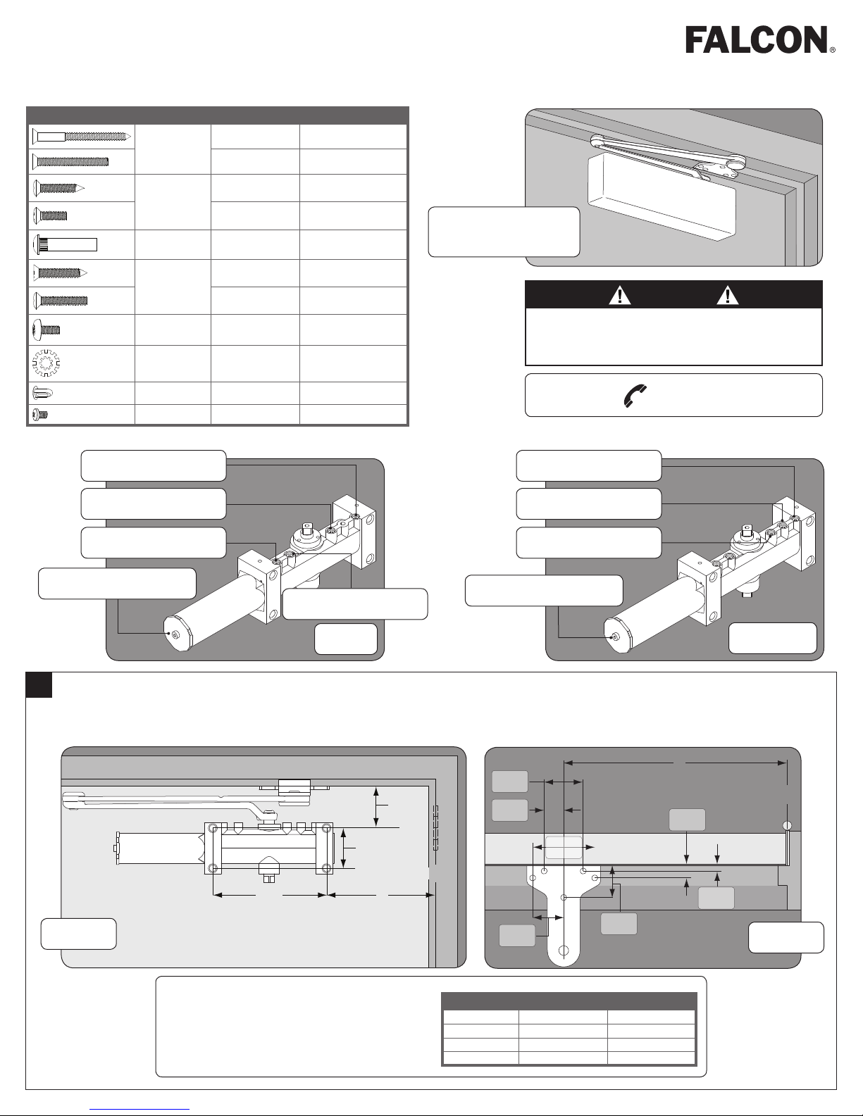
SC71 Series Closer
Installation Instructions
Forged Arm Models, SC71 (1-6 Adj.)
Fasteners Use Description Drill/Tap
Closer Body #14 Wood 1/8" Drill
1/4-20 #7 Drill, 1/4-20 Tap
Arm Shoe #14 Wood 1/8" Drill
1/4-20 #7 Drill, 1/4-20 Tap
Thru-bolt Wood/Metal 3/8" Drill
Fifth Hole
Spacer
Arm
Attachment
Arm
Attachment
Lock Washer
Cover Plug — —
Cover Screw — —
L=Latch Speed Valve
S/D=Main Speed Valve
#14 Wood 1/8" Drill
1/4-20 #7 Drill, 1/4-20 Tap
— —
— —
Closer mounted on push
side of door
(opposite of hinge side).
CAUTION
Improper installation or regulation may result in personal
injury or property damage. Follow all instructions
carefully. For questions, call Falcon at number below.
(877) 671-7011
L=Latch Speed Valve
S=Main Speed Valve
B=Backcheck Valve
Spring Power Adjustment
1
Door and Frame Preparation:
A. Choose degree of door opening.
B. Drill per appropriate fastener, using chart above.
Front View
Right Hand Door Illustrated. Same dimensions
apply for Left Hand Door measured from center
line of hinge.
"P" Valve, Normally Closed
SC71
S/D=Delay Action Valve
Spring Power Adjustment
Opening A B
Up To 100°
101° – 130°
131° – 150°
151° – 180°
8C\v" (222 mm) 10B\," (270 mm)
7Z\v" (184 mm) 9Z\," (232 mm)
6Z\v" (159 mm) 8Z\," (206 mm)
5Z\v" (133 mm) 7Z\," (181 mm)
SC71 DEL
Top View
Page 2
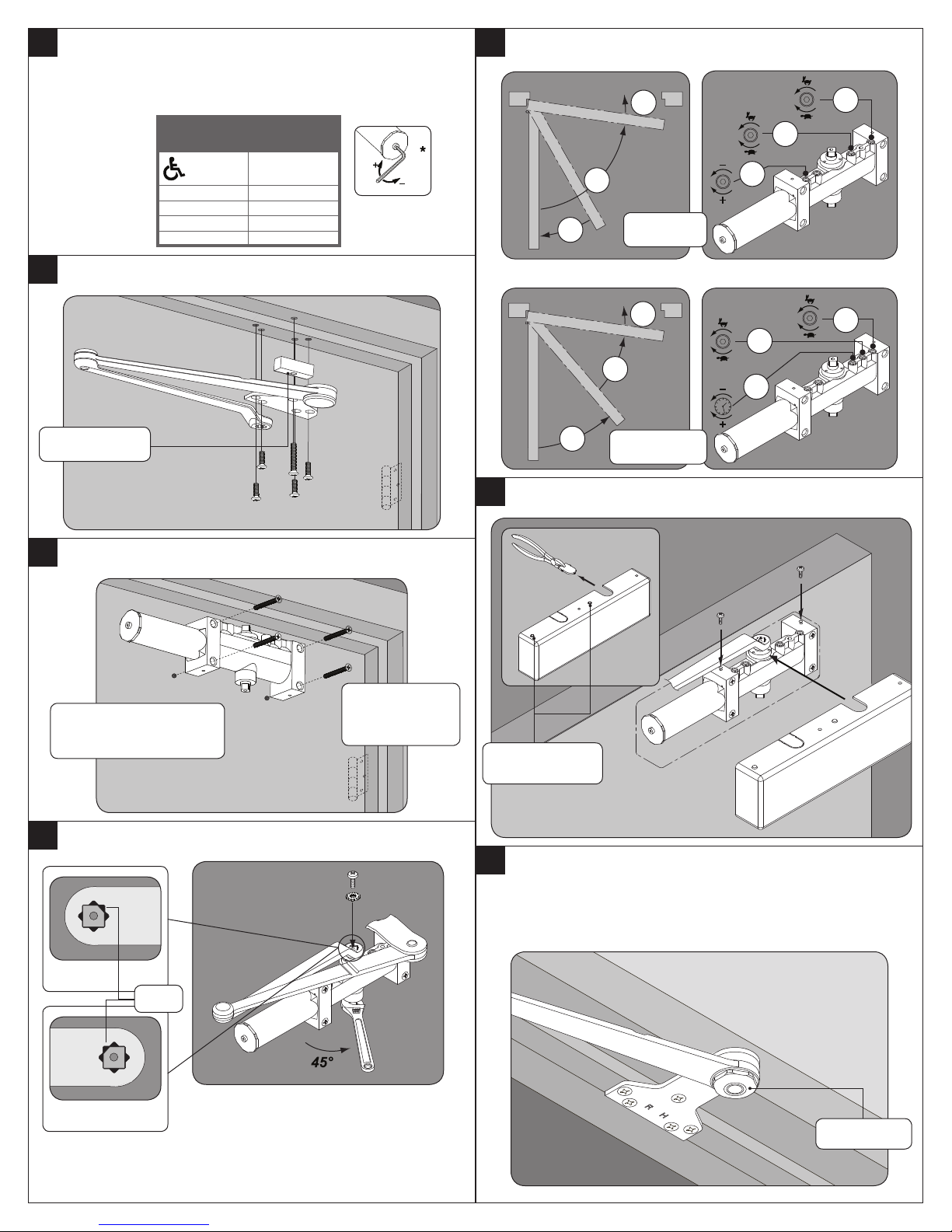
2
a
b
S/D
L
B
S/D
L
B
S
L
D
L
S
D
RH
LH
Determine door width, adjust spring power to match
chart.
* Door closer is shipped with +9 turns.
6
Adjustment Instructions.
Door
Width
32" (815 mm) +5
36" (915 mm) +9
42" (1050 mm) +15
48" (1220 mm) +21
3
Install arm & shoe assembly onto frame.
Fifth Hole Spacer
4
Install closer onto door.
Power
Adjustment
0
— — — — — OR — — — — —
SC71 DEL
7
Attach cover with screws.
SC71
Valves UP for Right hand
door (shown). Valves DOWN
for Left hand door.
5
Attach main arm to closer.
LH
RH
Flat
Spring tube faces
away from hinge
edge.
Insert cover plugs
(RH Shown)
8
To adjust optional handed hold-open arm:
A. Loosen hold-open nut.
B. Open door 5° less than desired position and tighten hold-open
nut securely.
Hold-open nut
Page 3

2¹⁄₂"
(64 mm)
2³⁄₈" (60 mm)
6³⁄₄"
(171 mm)
A
C
L
Del gozne
Charnière
¹¹⁄₁₆"
17 mm
B
⁵⁄₁₆"
8 mm
1³⁄₄"
44 mm
1¹¹⁄₁₆"
43 mm
3³⁄₈"
86 mm
1¹⁄₁₆"
27 mm
2¹⁄₈"
54 mm
C
L
Del gozne
Charnière
Cerrador de Puerta Serie SC 71
Instrucciones de instalación
Modelos con brazos forjados, SC71 (1-6 Adj.)
Sujetadores Aplicación Descripción Perfore/ Roscas
Ferrures D'application Description Percez/ Taraud
Cerrador de
Puerta
Ferme-porte
del brazo y de la
zapata
du bras et de la
console
Thru-bolt
Thru-bolt
Espaciador para
el quinto agujero
Espaceur du
cinquième trou
Brazo
Le bras
Brazo
Le bras
#14 Madera
#14 Bois
1/4-20
1/4-20
#14 Madera
#14 Bois
1/4-20
1/4-20
Madera/Metal
Bois/Métal
#14 Madera
#14 Bois
1/4-20
1/4-20
1/8" Perfore
1/8" Percez
#7 Perfore, 1/4-20 Roscas
#7 Percez, 1/4-20 Taraud
1/8" Perfore
1/8" Percez
7 Perfore, 1/4-20 Roscas
#7 Percez, 1/4-20 Taraud
3/8" Perfore
3/8" Percez
1/8" Perfore
1/8" Percez
7 Perfore, 1/4-20 Roscas
#7 Percez, 1/4-20 Taraud
Ferme-porte Série SC 71
Instrucions d’installation
Modèle à bras forgé, SC71 (1-6 Adj.)
ADVERTENSIA
Una instalación o un ajuste
incorrectos pueden resultar en
daño personal o material. siga bien
todas las instrucciones. para más
informaciones, ilama a Falcon al
Cerrador montado al lado
del empuje de la puerta
(opuesto al lado del gozne).
Ferme-porte installé sur le
côté à pousser de la porte
(à lopposé du côté de la
charnière).
DANGER
Une installation ou un réglage
inadéquats peuvent entraÎner
des blessures ou des dommages.
Veuillez suivre toutes les
instructions avec soin. Pour plus de
renseignments, composez le
Los tapones de tapa
Les bouchons de couvercle
Las tuercas la tapa
Les vis couvercle
L=Velocidad del seguro L=Vitesse de verrouillage
S/D=Velocidad principal S/D=Vitesse de fermeture
B=Resistencia de apertura
Adjuste de la
potencia del resorte
Válvula P normalmente cerrada
Soupape P habituellement fermée
1
Preparación de la puerta y del cuadro:
Réglage de la force
B=Résistance douverture
du ressort
A. Elija el grado de apertura de la puerta.
B. Taladre según la fijación correcta, usando la tabla precedente.
SC71
(877) 671-7011
L=Velocidad del seguro L=Vitesse de verrouillage
S=Velocidad principal
S/D=Soupape de
retardement
Adjuste de la
potencia del resorte
S=Vitesse de fermetur
S/D=Válvula
de retardación
Réglage de la force
du ressort
(877) 671-7011
SC71 DEL
Préparation de la porte et du cadre:
A. Sélectionnez le degré douverture désiré;.
B. Percer en fonction des vis convenables utilisées à l'aide du
diagramme ci-dessus.
Vista frontal
Vue de face
Puerta Mano Derecha Ilustrada. Las mismas
dimensiones se aplican para puertas de mano
izquierd, medidas a partir de la línea central de la
Porte Main Droite Illustrée. Les mêmes dimensions
sappliquent pour une porte main gauche, mesurées à
partir du centre de la charnière.
bisagra.
apertura A B
Up To 100°
101° – 130°
131° – 150°
151° – 180°
8C\v" (222 mm) 10B\," (270 mm)
7Z\v" (184 mm) 9Z\," (232 mm)
6Z\v" (159 mm) 8Z\," (206 mm)
5Z\v" (133 mm) 7Z\," (181 mm)
vista desde arriba
Vue de dessus
l'ouverture A B
Up To 100°
101° – 130°
131° – 150°
151° – 180°
8C\v" (222 mm) 10B\," (270 mm)
7Z\v" (184 mm) 9Z\," (232 mm)
6Z\v" (159 mm) 8Z\," (206 mm)
5Z\v" (133 mm) 7Z\," (181 mm)
Page 4

2
a
b
S/D
L
B
S/D
L
B
S
L
D
L
S
D
RH
LH
Determina la anchura de la
puerta. Ajuste la potencia
delresorte según lo
indicado en el gráfico.
* Cerrador mandado con +9
vueltas.
Mesurez la largeur de la
porte. Réglez le ressort
selon les indications du
tableau.
* Ferme-porte expédié avec +9
révolutions.
6
Instrucciones de ajuste. Instructions de réglage.
De espesor
de puerta
32" (815 mm) +5 32" (815 mm) +5
36" (915 mm) +9 36" (915 mm) +9
42" (1050 mm) +15 42" (1050 mm) +15
48" (1220 mm) +21 48" (1220 mm) +21
3
Instale el ensamblaje del
brazo.
Espaciador para el quinto agujero
Espaceur du cinquième trou
4
Monte el cerrador en la
puerta.
Adjuste de
potencia
0 0
Largeur de
la porte
Installez l’assemblage du
bras.
Installez le ferme-porte sur
la porte.
Regler la
puissance
— — — — — OU O — — — — —
7
Sujeta la tapa con las
tuercas.
SC71
SC71 DEL
Fixez le couvercle avec les
vis.
Válvulas ARRIBA para puerta
mano derecha (ilustrada).
Válvulas ABAJO para puerta
mano izquierda.
VSoupapes vers le HAUT
pour porte main droite
(illustrée). Soupapes vers le
BAS pour porte main gauche.
5
Coloque el brazo principal
al cerrador.
LH
RH
Plano
Plats
Attachez le bras principal
au ferme-porte.
Tubo resorte cara
opuesta al borde
del gozne.
Ressort tube fait
face à lopposé
du bord de la
charnière.
Inserte los tapones de
tapa (RH demostrado)
Insérez les bouchons de
couvercle (RH montré)
8
Para ajustar el brazo
de retención a mano
opcional:
A. Afloja la tuerca de retención.
B. Abre la puerta a 5° de
menos que la posición deseada
y aprieta bien la tuerca de
retención.
La tuerca de retención
Resserrez la vis
Pour régler le bras
avec retenue à main
optionnelle:
A. Desserrez la vis de retenue.
B. Ouvrez la porte 5° de moins
que la position désirée et
resserrez la vis..
© Allegion 2014
Printed in U.S.A.
43722 03/14-b
Page 5

Additional Notes: Revision History Revision Description:
B > Revised artwork
1. None A B C D E F
N/A 047232
Material
White Paper
Edited By Approved By EC Number Release Date
D. Myers M. Sasso 047232 02-17-14
Notes
1. printed two sides
2. printed black
3. tolerance ± .13
4. printed in country may vary
5. drawings not to scale
Title
SC71 Series Forged Arm Instruction Sheet
Creation Date
01-03-12
Number
43722
Revision
B
Created By
N/A
Activity
3899 Hancock Expwy
Security, CO 80911
© Allegion 2014Software: InDesign CS6
17.00
11.000
BEGINNING SHEET
FRONT
Page 1Page 4
Page 3Page 2
4.25
11.00
FRONT
FOLDED SHEET
 Loading...