

Page 1

Three Wheel Power Scooter
Item # S37600, S37601
Page 2

CONTENTS
I. INTRODUCTION....................................................3
II. SPECIFICATIONS AND STRUCTURE..................4-6
III. INITIAL ASSEMBLY...............................................7-8
IV. DISASSEMBLY.......................................................9
V. ADJUSTMENTS.....................................................10
VI. OPERATION...........................................................11-12
VII. BATTERY AND CHARGING..................................13-15
VIII. CARE AND MAINTENANCE.................................16-17
IX. SAFETY ..................................................................18-22
X. ELECTROMAGNETIC INTERFERENCE...............23-24
XI. WARRANTY INFORMATION.................................25-26
2
Page 3

INTRODUCTION
Thank you for purchasing the Falcon. This scooter design combines the most advanced state-of-the-art
components with modern, attractive styling.
Many Important safety, operating, and maintenance instructions are included in this Owners Manual. We urge
you to read the entire manual carefully and seriously before you attempt to operate your scooter for the first time.
These instructions were compiled for your benefit. Your understanding of these instructions is essential for the safe
operation of your new scooter.
Drive is not liable for damage to property or personal injury from the failure of any person and / or user to follow
the instructions and recommendations set forth in this manual or any other precautions contained on the scooter.
If you experience any problems with your scooter that you are not able to solve,or if you do not feel capable of
safely following any of the instructions and / or recommendations contained in this manual, please contact your
provider or authorized maintenance company for assistance.
Once you understand how to operate and take care of your scooter, we are sure that it will give you years of
trouble-free service and enjoyment.
These icons shown below, which appear in the entire manual, are used for reminding you especially to pay
attention to them. All of them are related with your safety. So it is strongly recommended that you should read
carefully and understand them completely.
WARNING!
This icon indicates that serious personal injury could occur if the information in this
!
!
manual is ignored.
CAUTION!
This icon indicates that the scooter may experience service failure if the information in
this manual is ignored.
3
Page 4
II. SPECIFICATIONS AND STRUCTURE
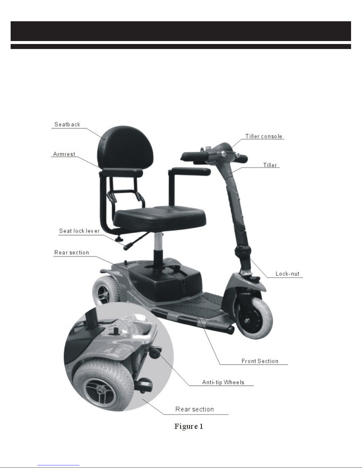
Your scooter mainly consists of four parts, a front section, a rear section, a seat unit and battery. A tiller console,
handle bar and a footplate are located on the front section. A driving motor, a brake system and the control
electronics are located on the rear section. The seat unit contains a seatback and armrests, etc. (see fig. 1)
4
Page 5
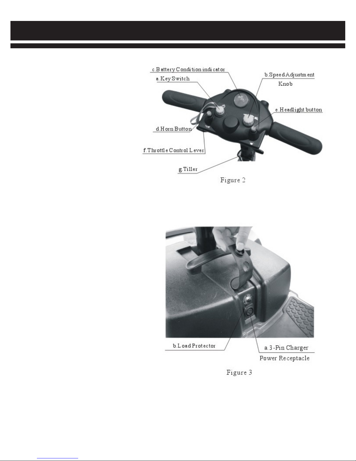
TILLER CONSOLE (see fig. 2)
a. Key Switch
b. Speed Adjustment Knob
c. Battery Condition indicator
d. Horn Button
e. Headlight Button
f. Throttle Control Lever
g. Tiller
II. SPECIFICATIONS AND STRUCTURE
CHARGING AND CONTROL SYSTEM (see fig. 3)
a. 3-pin Charger Power Receptacle
b. Load Protector
SEAT UNIT
a. Seat Base
b. Seatback
c. Armrests
d. Seat Lock Lever
5
Page 6

II. SPECIFICATIONS AND STRUCTURE
SPECIFICATIONS
Drive Wheel 7.3” (186mm) solid wheel
Front Wheel 7.16” (182mm) solid wheel
Anti-tip Wheel 2.2” (56mm) solid wheel
Limit Speed Forward speed, 6 km/h, rev. speed 3.5 km/h
Braking System Intelligent brake
Distance between Ground and Footplate 3.5” (90mm)
Turning Radius 31.5” (800 mm)
Dimensions 37.4” x 16.6” x 32.4” (950 x 500 x 825 mm)
Seat Unit Standard light backrest w/folding sponge seat
Drive System Single motor drive
Batteries 12v/12Ah x 2 pcs
Motor Power 24v 180w
Travel Ranging 10.5 miles (17 kilometers)
Charger 24v 2A portable
Weight capacity Rated of 165 lbs (75kg.) maximum
Climbing Slope Rated of 8 maximum of 12
Charging Time 10-12 hours
Main frame: 53 lbs. (24kg)
Seat Unit: 22 lbs. (10kg)
Component Weight Batteries: 19.8 lbs. (9 kg) per unit
6
Page 7
III. INITIAL ASSEMBLY
For convenience of transportation and reduction of possible damage, the batteries and the seat unit are separately
packaged, so you need to assemble them onto the main frame of your scooter.
OPENING THE PACKING BOX
Open the packing box of your new scooter, and take off all protective liner, then take the scooter
from the box.
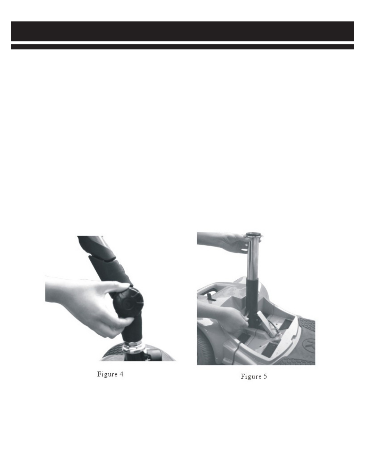
ADJUSTING ANGLE OF TILLER
• Loosen the lock-nuts(see fig. 4)
• Lift the tiller up to a proper angle for yourself
• Tighten the lock-nuts to fix the tiller
ASSEMBLING THE SEAT SUPPORT
• Insert the seat support into the seat tube located on the rear section(see fig. 5)
• Align the bolt hole
• Insert the bolt into the hole
7
Page 8
III. INITIAL ASSEMBLY
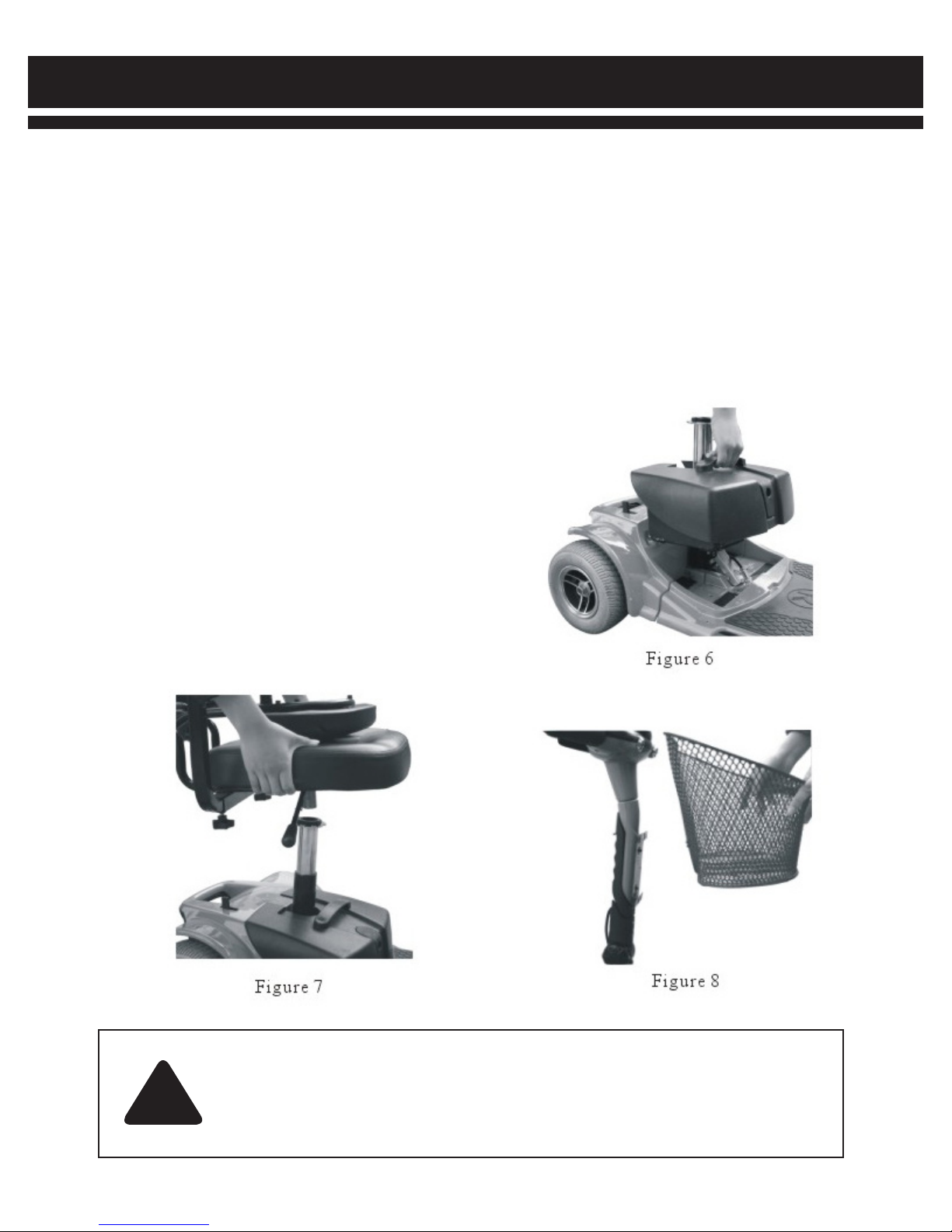
ASSEMBLING BATTERY UNIT
Put battery into trough, align electrode terminal on battery with that in the trough
(see fig. 6)
Turn safety lock on the back of the scooter that holds the battery in position.
ASSEMBLING SEAT UNIT
• Put the seat onto the seat support(see fig. 7)
• Pull out the seat-lock lever, adjust seat to the position, as you like. The seat will be locked
automatically.
• Insert left and right armrests into square tube separately
• Adjust to the position, as you like and lock-nuts.
ASSEMBLE BASKET
• Take off the 2 screws located on the front
of tiller(see fig. 8)
• Place basket on the front of tiller.
• Insert the net-basket into the receiver
Note: The basket can be ordered separately.
CAUTION!
Please always keep the electrode clean before installment, if not, it will influence the
!
effect of contact between battery packs and electrode terminal.
Wrong connection of battery will cause the scooter to be out of operation.
8
Page 9
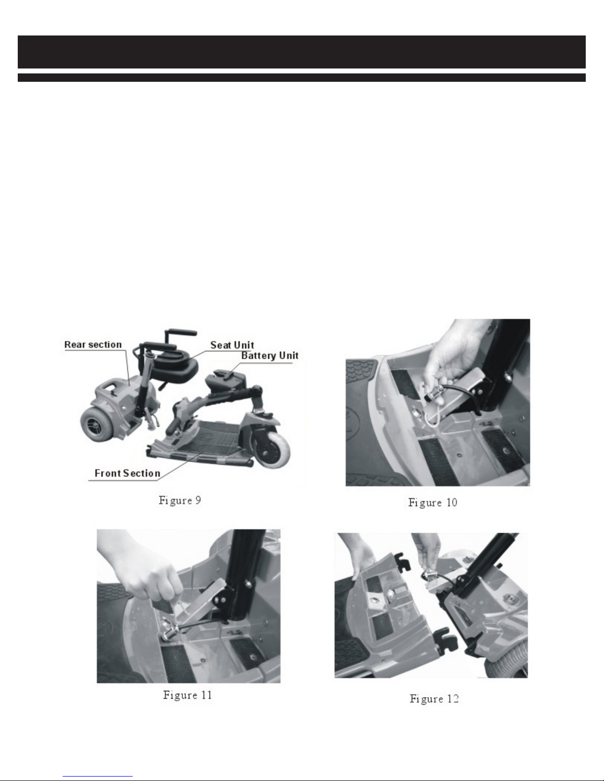
IV. DISASSEMBLY
For convenience to transport and store, your scooter has been designed to be disassembled and be assembled
easily without any special tools. You can easily disassemble the scooter into four pieces, the front section, the rear
section, the seat unit and the batteries (see fig. 9). You can assemble these pieces together quickly when you
follow these instructions.
DISASSEMBLY
• Shut off the power and pull the lock lever under the seat base to unlock the seat
• Lift the seat up and off the scooter(see fig. 7)
• Turn release lever on back of scooter to release the battery
• Lift the battery case up(see fig. 6)
• Loosen the plug from the front and rear power connector, then remove it(see fig. 10)
• Pull the ring on the lock hook and move it forward to release the two sections(see fig. 11)
• Lift the front and rear section from the middle(see fig. 12)
• Loosen the knob on the end of tiller, the incline the tiller(see fig. 4)
9
Page 10

V. COMFORTABLE ADJUSTING
WARNING!
Remove the key from the key switch before adjustments. Never attempt to do
!
Before operating the scooter, you may find the need to make some adjustments to increase your comfort, such
as seat height, armrest width, and tiller angle, etc.
SEAT HEIGHT ADJUSTMENT
• You can choose the different holes to change the seat height.
• Pull back the seat lock lever under the right side of the seat to
unlock the seat.
• Lift the seat up and off the scooter(see fig. 7)
• Hitch the pin loop and pull out the pin(see fig. 5)
• Slide the seat post up or down to change the seat height
as you need.
• Re-insert the pin.
• Re-install the seat.
adjustments while the scooter is in motion.
SEAT ROTATION
• You can rotate the seat to adjust its direction (see fig. 13)
• Pull up the seat lock lever to unlock the seat.
• Rotate the seat to desired position.
• Release the seat lock lever, it will relock the seat
automatically.
ARMREST WIDTH ADJUSTMENT
You can move the armrests inward or outward to adjust the
seat width(see fig. 14)
• Find the screw on the bottom of the armrest adjustment rack.
• Loosen the screw.
• Move the armrests inward or outward to the desired position.
• Tighten the screw.
10
Page 11

VI. OPERATION
TILLER CONSOLE
The tiller console houses all of the controls needed to drive your scooter,including the key switch, the speed
adjustment knob, throttle control lever, battery condition indicator, horn button and headlight button. With all of the
controls on the console you can control various motions of your scooter.
POWER SWITCH ( See fig. 2)
• Plug the key into the power opening
• Indicator on the gauge illuminates
• Plug out the key, power indicator is off
Warning! Do not use the key switch to stop your scooter unless an urgent event has
happened.
!
THROTTLE CONTROL LEVER (See fig. 2)
This lever allows you to control the forward speed and the reverse speed of your scooter up to the
maximum speed you preset with the speed adjustment knob.
• Use your thumb to press the lever to disengage the brakes and start moving.
• The further the lever is pushed, the faster the speed of your scooter.
• When you release the lever completely, it automatically returns to the primary position, i.e., the
stop position, and engages your scooter’s brakes to slow the scooter until it stops completely.
Warning! If your scooter has stopped for a long period, power down to prevent
unintended motion.
Warning! If your scooter makes unintended motion, please release the throttle control
lever immediately. The scooter will automatically stop unless this lever is out of order.
!
SPEED ADJUSTMENT KNOB
This knob allows you to preset and limit your scooter’s top speed. Maximum forward speed is approximately 4
mph, maximum reverse speed is approximately 1.5 mph.
Caution! Before you master the operation of your scooter, you should preset the speed
!
BATTERY CONDITION INDICATOR
When your scooter is powered up, this indicator shows the remaining capacity of the batteries by 3
color ranges on panel: red, yellow and green.
• When pointing to green, this indicates that the batteries are fully charged.
• When pointing to yellow, this indicates that half capacity of the batteries remains, and it needs to
be recharged.
• When pointing to red, this indicates that the batteries have been fully discharged, and it needs
to be charged immediately.
adjustment knob to the lowest position.
11
Page 12

VI. OPERATION
HORN BUTTON (see fig. 2)
This button activates a warning horn.
HEADLIGHT BUTTON (see fig. 2)
This button activates headlights.
OFF-BOARD CHARGER (see fig. 3)
Lift the cover on the battery case, so that you can use the off-board
charger to charge your batteries through a 3-pin charger power
receptacle in the middle of the scooter.(see VII, Batteries and
Charging)
LOAD PROTECTOR (see fig. 3)
The load protector is a safety device. When the overload occurs, this
protector automatically trips to protect the motor and other electric devices.
When the protector trips, your scooter must be powered immediately. Wait a few minutes before you press the
button on the load protector, which is located under the cover at the rear section of the scooter. After that you can
power up and drive normally.
MANUAL FREEWHEEL LEVER
There is a freewheel lever at the low right of the seat base,(see fig. 15) Whenever you do not want to move your
scooter by motor, you can put it in freewheel mode.
• Pull forward on the manual freewheel lever to disable the drive motor and change to the freewheel
mode.
• Push backward on the manual freewheel lever to re-engage the drive motor and take your scooter
out of the freewheel mode.
Caution! When your scooter is in freewheel mode, the brake system is disabled.
Caution! Never use your scooter in freewheel mode without an attendant. Failure
to do so may cause personal injury.
Caution! Never put your scooter in freewheel mode on any incline. Failure to do
so may cause personal injury.
Warning! When your scooter is in powered mode, the manual freewheel lever
must be in downward position, i.e. in powered mode, so as to guarantee the
!
3-PIN CHARGER POWER RECEPTACLE
This receptacle is used to connect to the charger. When the batteries are charged, this receptacle makes your
scooter out of work.
brake system to work normally. Failure to do so may cause personal injury.
Warning! A wrong connection may cause damages to the charger, connectors, and
!
electronics.
12
Page 13

VII. BATTERY AND CHARGING
Your scooter uses two long lasting, 12-volt deep cycle batteries. These batteries are sealed and maintenance
free. Since they are sealed, there is no need to check the electrolyte(fluid)level. Deep cycle batteries are designed
to handle a longer and deeper discharge. Though thay are similar in appearance to automotive batteries, they are
not interchangeable. Automotive batteries are not designed to handle a long, deep discharge, and also are unsafe
for use in your scooter.
Warning! Battery posts, terminals, and related accessories contain lead and lead
!
CHARGING YOUR BATTERIES
The battery charger is essential in providing long time for your scooter batteries. This charger can charge your scooter’s
batteries safely, quickly and easily.
!
compounds. Wash your hands after handling.
Warning! You must charge your scooter’s battery with the supplied off-board battery
charger. Do not use an automotive-type battery charger.
CHARGING YOUR BATTERIES WITH THE OFF-BOARD CHARGER
• Position your scooter near a standard wall outlet.
• Lift the cover on the battery case.
• Ensure that the scooter is powered off.
• Plug the output connector of the off-board charger into the 3-pin charger power receptacle.
• Plug the input connector of the off-board charger into the wall outlet.
• The red light on the charger turns on to indicate the charger is on.
• When charging is complete, the green light turns on.
• It is recommended that you charge your batteries for 10-12 hours.
• When the batteries are fully charged, unplug the off-board charger from the wall outlet and then
from the 3-pin charger power receptacle.
• Put the charger with it’s cord in a safe place.
• The battery can also be charged off-scooter.
Warning! The battery should be stored on a clean,dry, flat and inconductive
!
NEW BATTERY’S USAGE
To break in new batteries for maximum efficiency, please follow the instructions below:
• Fully recharge any new battery prior to it’s initial use. This brings the battery up to about 90% of it’s peak
performance level.
• Operate your scooter throughout your house and yard. Move slowly at first, and do not stray too far until
becoming accustomed to your scooter and know how to control the driving distance from the battery
condition indicator.
• Give the batteries another full charge of 10 to 12 hours and operate your scooter again. The batteries will
now perform at over 90% of their potential.
• After 4 or 5 charging cycles, the batteries will top off at 100% charge and last for an extended period.
surface, otherwise the battery will cause fire dander.
13
Page 14

VII. BATTERY AND CHARGING
FREQUENTLY ASKED QUESTIONS (FAQs)
The battery charger takes the standard wall outlet voltage(alternating current) and converts it to 12V DC(direct
current). This scooter’s batteries use direct current to run your scooter. When the battery voltage is low, the
charger sends more current to the batteries so that the charger has a higher temperature, this is normal. When
the batteries are fully charged, the current sent to them is at nearly zero. Therefore when the charger is
Plugged in, it does not overcharge the batteries.
Important note! Your scooter’s charger will not operate after the batteries have been discharged to nearly zero
voltage, call your provider or authorized dealer.
CAN A DIFFERENT CHARGER BE USED?
You should use the off-board charger supplied with your scooter. It is the safest, most efficient tool to charge the
batteries. We do not recommend using other types of chargers
(e.g. an automotive battery charger).
HOW OFTEN MUST THE BATTERIES BE CHARGED?
You can charge the batteries as soon as you are finished using your scooter. This is for the benefit of prolonging
the life of the batteries.
Infrequent Use:
If you use your scooter infrequently(once a week or less), you should charge the batteries at least once per
week for 10-12 hours.
Note! Keep the batteries in a dry place and avoid deeply discharging your batteries. Do
not charge the batteries for more than 24 hours at a charging cycle.
!
HOW CAN I GET MAXIMUM RANGE PER CHARGE?
Rarely do you have an ideal driving situation such as smooth, flat, hard terrain with no
hills or curves. More often you are presented with hills, sidewalk cracks, uneven and loosely packed surfaces,
and curves. All of these factors will affect the running distance or running time per battery charge. Below are a
few suggestions for obtaining the maximum range per charge.
• Always charge the batteries fully prior to your trip.
• Plan your trip in advance to avoid inclines if possible.
• Limit baggage weight to essential items.
WHAT TYPE OF BATTERIES SHOULD I USE?
We recommend deep-cycle batteries that are sealed
and maintenance free. Both SLA and Gel-Cell are
deep-cycle batteries that are similar in performance.
Refer to the following specifications to reorder deepcycle batteries.
Type Deep-cycle sealed lead-acid
Or gel cell
Size 6” x 3.9” x 3.75” (152 x 99 x 96mm)
Voltage 12 Volts each
Amperage 12AH(amp hours)
14
Page 15

VII. BATTERY AND CHARGING
Deep-cycle batteries employ a much different chemical technology than that used in car batteries, nickelcadmium, or in other common battery types. Deep-cycle batteries are specifically designed to provide power,
drain down their charge, and then accept a relatively quick recharge. AGM and gel-cell batteries should be
charged as often as possible. They do not have a “memory” like nickel-cadmium batteries.
We work closely with our battery manufacturer to provide a battery that best suits your scooter’s specific
demands. Fresh batteries are promptly shipped with a full charge. During shipping, the batteries encounter
temperature extremes that may influence initial performance. Heat robs the charge from the batteries, and cold
slows the power available and extends the time needed to recharge the batteries(just as with a car battery). It
might take a few days for the temperature of the battery to stabilize and adjust to it’s new ambient temperature.
More importantly it will take a few “recharging cycles”(a partial drain-then a full recharge) to establish the critical
chemical balance that is essential to the battery’s peak performance and long life. It will be worthy to take some
time to break in your battery properly.
Caution:The useful life of a battery is quite often a reflection of the care it receives.
!
HOW CAN I ENSURE MAXIMUM BATTERY LIFE?
A fully charged deep-cycle battery will provide a reliable performance and extended battery life. Keep your
scooter’s batteries fully charged whenever possible. Batteries that are regularly and deeply discharged,
infrequently charged, or stored without a full charge may be permanently damaged, causing unreliable operation
and limited battery life.
HOW SHOULD I STORE MY SCOOTER AND IT’S BATTERIES?
If you do not use your scooter regularly, we recommend maintaining battery life by charging the batteries at least
once per week.
If you do not plan on using your scooter for an extended period, fully charge the batteries prior to storage.
Disconnect the battery harnesses and store the scooter in a warm, dry environment. Avoid temperature
extremes, such as freezing and excessively hot conditions, and never attempt to charge a frozen battery. A cold
or frozen battery should be warmed for several days prior to recharging.
Warning! Do not attempt to charge a cold or frozen battery. You should warm them up
!
for several days prior to charging.
WHAT ABOUT TRANSPORTATION?
AMG and gel-cell batteries are designed for application in a scooter and other mobility vehicles. These batteries
are allowed for safe transportation on aircraft, buses, and trains, as there is no danger of spillage or leakage. We
suggest you contact the carrier’s company in advance to determine that carrier’s specific requirements.
15
Page 16

VIII. CARE AND MAINTENANCE
Your scooter, like any motorized vehicle requires a routine maintenance check. Preventative maintenance is very
important. You can perform some of these regular checks by yourself. If you follow the maintenance checks in
this section as scheduled, you can help ensure that your scooter gives you years of trouble-free operation.
MOISTURE
You should avoid positioning your scooter in damp areas of any kind. Direct exposure to water or dampness
could cause your scooter to malfunction electronically and mechanically. Moisture can cause electrical
components to corrode and the scooter’s frame to rust.
Should your scooter come in contact with water:
• Dry your scooter as thoroughly as possible with a towel
• Allow your scooter to sit in a warm, dry place to get any moisture to evaporate
• Make safety checks of all of the operations before using your scooter
• If any inconsistencies are found, contact an authorized Drive provider
TEMPERATURE
• Some of the parts of your scooter are susceptible to extreme changes in temperature. Always keep
your scooter in proper range of temperature.
• In extreme cold temperature, the batteries may freeze. The temperature at which they may freeze
depends on a number of factors, such as battery charge, usage and composition of batteries
(e.g. AGM or Gel-cell).
• Temperatures above 100 degrees may cause your scooter to operate at a reduced speed. This
reduced speed is a safety feature built into the controls that helps prevent damage to the motor and
other electrical components.
GENERAL GUIDELINES
• Avoid knocking or bumping the consoles.
• Avoid prolonged exposure of your scooter to extreme conditions, such as heat, cold or moisture.
• Keep the tiller console clean.
• Check all connectors to ensure that they are tight and secured properly.
• Check all electrical connectors including the charger’s connectors. Make sure they are all tight and are
not corroded. Batteries must sit flat in the battery case.
• A yellow light turns on that indicates a half capacity of the battery has been consumed, and they need to
be charged, but the scooter can be used, but the battery is close to full discharge.
• When the red light is on, that indicates that the batteries have been fully discharged, and they need to
be charged immediately.
• A full charge will take up to 7 hours
• The body should have been sprayed with a clear sealant coating. You can apply a light coat of car wax
to help it retain it’s high gloss appearance.
• All wheel bearings are prelubricated and sealed. They require no subsequent lubrication.
16
Page 17

VIII. CARE AND MAINTENANCE
Caution! If you do not use the scooter for a long period, its recommended that you block
up your scooter so that the tires do not touch the ground. This prevents flat spots from
!
DAILY CHECK
• With the power off, check the throttle control lever. Make sure it returns to the primary position when you
release it.
• Check the right/left lock-nuts on the low end of the tiller. Make sure it is fastened to the tiller. Make sure
the battery lock knob is engaged.
WEEKLY CHECK
• Check all electrical connectors. Make sure they are not loose or corroded.
• Check the body joint bolt. Make sure the bolt is tightened.
• Check the brakes. This test should be carried out on an even surface with at least three feet of
clearance around your scooter.
forming on the tire.
MONTHLY CHECK
• Check the anti-tip wheel. Make sure it does not touch the ground.
• Make sure it is not seriously worn, otherwise you should change it.
• Check the drive wheels for wear. If it needs to be repaired, contact an authorized provider.
• Keep your scooter clean and free of foreign material, such as hair, food, drink, dust and mud, etc.
YEARLY CHECK
• Take your scooter to an authorized provider for yearly maintenance. This helps ensure that your scooter
is functioning properly and helps prevent future complications.
STORAGE
Your scooter should be stored in a dry place, free from temperature extremes. Otherwise, the frame, the
connections, and the electronics may rust and damage. During it’s storage, disconnect the batteries from the
scooter.
CLEANING
• Never use a hose on your scooter or place it in direct contact with water.
• Your scooter has an ABS plastic body shroud that allows it to be easily wiped clean
with a damp cloth.
• Never use any chemicals to clean the seat, as they may cause the seat to become slippery or dry out
and crack. Clean with a damp cloth or neutral soapy water and dry the seat thoroughly.
17
Page 18

IX. SAFETY
PRE-RIDE SAFETY CHECK
A safety check is recommended before each use to make sure your scooter operates smoothly and safely.
See VIII “CARS AND MAINTENANCE”.
Perform the following procedures prior to using your scooter.
• Check all electrical connections. Make sure they are tight and not corroded.
• Check all connections to the battery box. Make sure they are secured properly.
• Check the brakes. See VIII “CARE AND MAINTENANCE”.
• Check the battery charge. See VII. “batteries and charging”.
WEIGHT LIMITATIONS
Your scooter is rated for a 250 lb. weight capacity.
Warning! Exceeding the weight limit voids your warranty and may result in personal
!
Injury and damage to your scooter.
INCLINE INFORMATION
Many buildings have ramps with specified degrees of inclination, designed for easy and safe access. Some
ramps may have turning switchbacks (180 degree turns) that require you to have good cornering skills on
your scooter.
When climbing an incline, try to keep your scooter moving. If you must stop to start up again, you should slowly
accelerate cautiously. When driving down an incline, do so by setting the speed to the slowest position and
pushing the forward/backward lever to the forward direction. If your scooter starts to move down the incline
faster than you anticipated or desired, allow it to come to a complete stop by releasing the throttle control lever.
Then rotate down the speed adjustment knob and then push the throttle control lever down slightly to ensure a
safely controlled descent.
Warning! When climbing an incline, do not zig-zag or drive at an angle up the face of
the incline. Drive your scooter straight straight up the incline. This greatly reduces the
!
!
Possibility of a tip or a fall. Always exercise extreme caution when negotiating an incline.
Warning! Don’t drive up or down a potentially hazardous incline (i.e. Areas covered with
snow, ice, cut grass, or wet leaves.
Warning! Never drive down an incline backwards. This could cause personal injury.
!
18
Page 19

IX. SAFETY
The maximum safe incline angle is 8 degrees for your scooter. If a slope is less than this angle, it is safe for your
scooter to climb or descend.
Warning! Any attempt to climb or descend a slope steeper than 8 degrees may put your
!
BRAKING INFORMATION
Your scooter is equipped with two powerful brake systems
• Electric brake system: This system can gradually slow and stop your scooter only when you release the
throttle control lever to let it return to the top/stop position during driving.
• Motor brake system: After the electric brake system slows your scooter to a near stop, a damper in the
motor brake system will automatically engage to make your scooter stop completely.
!
scooter in an unstable position, and cause it to tip, resulting in personal injury and/or
damage to your scooter.
Warning! When your scooter is traveling, the free-wheel lever should be in a downward
position, i.e. in powered mode. If not, the brake system disengage, and a dangerous
situation may be caused.
OUTDOOR DRIVING SURFACES
Your scooter is designed to provide optimum stability under normal driving conditions,
(dry, level surfaces composed of concrete, blacktop or asphalt. But you should avoid driving on the following
surfaces:
• A driving surface that you feel unsure about, like gravel or dirt.
• Tall grass that can become tangled in the motor.
• Loosely packed gravel, and sand.
FREE-WHEEL MODE
Your scooter is equipped with a manual free-wheel lever that allows the scooter to be manually pushed by an
attendant. For more information, see VI. “OPERATION”.
Warning! Do not use your scooter free-wheel mode without an attendant present. Failure
!
!
to do so may cause personal injury.
Warning! Do not attempt to place your scooter in free-wheel mode while seated on it.
Personal injury may result. Please ask an attendant for assistance if necessary.
Warning! Do not place your scooter in free-wheel mode while on an incline. The scooter
!
could roll uncontrollably down on it’s own, causing personal injury.
19
Page 20

IX. SAFETY
STATIONARY OBSTACLES (STEPS,CURBS,ETC.)
Warning! Do not attempt to negotiate a curb that has a height greater than 25mm
!
!
STREETS AND ROADWAYS
!
without an attendant.
Warning! Do not attempt to have your scooter proceed backwards down any step, curb,
or other obstacle. This may cause your scooter to tip and cause personal injury.
Warning!You should not operate your scooter on public streets and roadways. Obey all
local pedestrian traffic rules. Wait until your path is clear of traffic, and then proceed with
extreme caution.
IN OR OUTDOORS
• Determine in advance if the door opens towards or away from you.
• Use your hand to turn the knob or push the handle or push-bar.
• Drive your scooter gently and slowly forward to push the door open. Or drive your scooter gently and
slowly backward to pull the door open.
UP OR DOWN STAIRS OR ESCALATORS
Your scooter is not designed to travel up or down stairs or escalators. Always use an elevator.
Warning!Never use your scooter to negotiate steps or elevators. You may cause injury
!
IN OR OUT OF ELEVATORS
Modern elevators have a door edge safety mechanism that when you push,reopens the elevator door.
If you are in the doorway of an elevator when the doors begin to close, push on the rubber door edge or allow
the rubber door edge to contact the scooter and the door will reopen.
Take care that pocketbooks, packages,or scooter accessories do not become caught in elevator doors.
ELECTROMAGNETIC INTERFERENCE
Radio waves from mobile phones, radio receivers or other transmitters such as radio and TV stations could
affect your scooter’s performance if your scooter is in the range of their influence. See X “ELECTROMAGNETIC
INTERFERENCE”.
to yourself and others and damage your scooter.
20
Page 21

IX. SAFETY
SCOOTER TRANSPORT
There are no standards approved for tie-down systems in a moving vehicle of any type to transport a person
while seated ina scooter.
Anyone traveling in a motor vehicle should be properly secured in the motor vehicle with safety belts fastened
securely.
Warning! Do not sit on your scooter while it is in a moving vehicle. should be properly
!
!
!
secured in the motor vehicle with safety belts fastened securely.
Warning! Do not sit on your scooter while it is in a moving vehicle. Personal injury and
property damage may result.
Warning! Always be sure your scooter and it’s batteries are properly secured while it is
being transported. Failure to do so may cause personal injury and/or damage to your
scooter.
WEATHER PRECAUTIONS
Warning! Do not expose your scooter to any type of moisture at any time(rain, snow, mist
or wash).Such exposure can damage your scooter. Never operate your scooter if it has
!
!
GETTING ON OR OFF SCOOTER
Getting onto and off your scooter requires a good sense of balance.Assistance may be required from your
attendant when learning to get on or off your scooter.
To avoid an injury, please observe the following safety tips when getting on or off your scooter.
• Ensure that the power is turned off, see VI, “OPERATION”.
• Ensure that your scooter is not in free-wheel mode.
• The seat armrests are flipped up or moved out to make getting on or off the scooter easier.
• Keep the front wheel facing forward.
been exposed to moisture until it has dried thoroughly.
Warning! Do not operate you scooter on ice or slippery conditions, or on salted surfaces.
Doing so may cause you injury and affect the performance of your scooter.
21
Page 22

IX. SAFETY
Warning! Position yourself as far back as possible in the scooter seat to prevent the
!
!
!
BALANCE
Avoid reaching or bending while driving your scooter. When reaching, bending, or leaning while seated on your
scooter, it is important to maintain a stable center of gravity and keep the scooter from tipping.
scooter from tipping over and causing injury.
Warning! Avoid using your armrests for weightbearing purposes. Such use may cause
your scooter to tip over and cause you injury.
Warning! Avoid putting all of your weight on the footplate. Such use may cause your
scooter to tip over and cause you injury.
Warning! Do not reach,lean, or bend for objects on the floor when seated on your
scooter.Movements such as these may change your center of gravity and the weight
!
PREVENTING UNINTENDED MOVEMENT
!
LIMITATION TO MEDICINES AND ALCOHOL
Scooter users have to exercise care and common sense while operating their scooter. This includes awareness
of safety issues while under the influence of medication or alcohol. If the user consumes alcohol, or is taking
medication that affects their sense of reactive ability, never use the scooter.
!
distribution of the scooter and cause your scooter to tip, possibly resulting in your injury.
Warning!Turn off the power, even if you anticipate being in a stationary position for an
extended period of time. This will prevent unexpected motion from inadvertent throttle
control lever contact and electromagnetic interference. Failure to do so may result in
personal injury.
Warning! Do not operate your scooter while under the influence of alcohol or medication
that impairs your ability to drive your scooter safely.
Warning! It is strongly suggested for these users to consult their medical professionals
before operating their scooter, as some medications will affect their sense of reactive
!
ability, bringing a hidden danger in operating their scooter
22
Page 23

X. ELECTROMAGNETIC INTERFERENCE
EMI/RFI WARNINGS
Radio waves are a form of electromagnetic energy, and can cause unintended motion of electric mobility
vehicles. When electromagnetic energy adversely affects the operation of an electrical device, that adverse
effect is called “Electromagnetic Interference” or EMI, or “Radio Frequency Interference” or RFI.
WHERE DO RADIO WAVES COME FROM?
Radio waves are emitted from the antennas of celluar phone, mobile two-way radios (such as walkie-talkies),
radio stations, TV stations, amateur radio transmitters, wireless computer links, microwave sources, and paging
transmitters. Electromagnetic energy is more intense closer transmitting antennas. The greater transmission
strength is, the greater the concern to electric mobility vehicle users.
CAN I EXPECT MY SCOOTER TO MOVE IF EMI AFFECTS IT?
It is very difficult to predict, the effects of EMI on a scooter depend on a number of factors:
• The strength of the radio waves.
• The construction of your particular scooter.
• The location (whether it is on level ground, or on an incline) and direction of a scooter.
• Whether or not your scooter is in motion.
So if the unexpected incidents described below occur with your scooter, you should consider whether or not
there is a radio wave source nearby.
• Your scooter may come to a sudden stop in an uncontrolled manner.
• Your scooter may suddenly move in an uncontrolled manner.
• The brakes on your scooter may be released suddenly in an oncontrolled manner.
• The electronic components of control systems may be damaged for no reason at all.
Unfortunately, EMI/RFI may be difficult to recognize, because the signals from radio sources are invisible and
may be intermittent.
ARE ALL ELECTRIC MOBILITY VEHICLES SUSCEPTIBLE TO EMI?
Each make and model of electronic mobility vehicle differs in its ability to resist EMI. Each mobility vehicle has a
particular level of resistance to EMI.This resistance measured in volts per meter (v/m). A higher resistance level
offers greater protection against EMI.In other words, an electric mobility vehicle with a high resistance level is
less likely to be affected by a strong radio source that is an electric mobility vehicle with a low resistance level.
23
Page 24

X. ELECTROMAGNETIC INTERFERENCE
HOW TO PREVENT EMI
Here are some precautions you can take:
• Do not turn on or use hand-held personal communication devices such as, Citizens Band (CB) radios
and cellular phones while your scooter is turned on.
• Try not to operate your scooter too close to the transmitters, such as radio, TV stations and hand-held
or mobile two-way radios. For example, if you are on an electric mobility vehicle with a resistance level
of 20v/m, you should remain at least 3 feet (1 meter) from a hand-held two-way radio and at least
(1 foot) 30 centimeters from a mobile two-way radio.
• Be aware that adding accessories and/or components, or modifying your scooter in any way may
change it’s EMI resistance level and may make it more susceptible to interference from radio wave
sources. There is no simple way to evaluate the effects of such actions on the resistance level of a
scooter.
If unintended motion or unintended brake release occurs, turn off your scooter by removing the key as soon as
possible.
24
Page 25

XI. WARRANTY
W A R R A N T Y
Your Drive brand product is warranted to be free of defects in materials and workmanship as follows:
Chair/Scooter frame: Lifetime
Electronic Controller and drive train components: 1 year
Batteries: 6 months from time of installation
WARRANTY CONDITIONS:
1. Any work or replacement part installation must be carried out by an authorized Drive dealer/
service agent.
2. Should your power chair require attention under this warranty, please contact an authorized
Drive dealer.
3. Any repaired or replaced parts will be covered by this warranty for the balance of the
warranty period on the power chair.
4. The above warranty conditions apply to an new power chair purchased at the full retail price.
If you are unsure whether your power chair is covered, check with an authorized Drive dealer.
5. Under normal circumstances, no responsibility will be accepted where the power chair has
failed as a direct result of:
a. The power chair part not having been maintained in accordance with the
manufacturer’s recommendations.
b. Failure to use the manufacturer’s specied parts.
c. The power chair or part having been damaged due to neglect, accident or improper use.
d. The power chair or part having been altered from the manufacturer’s specications or
repairs having been attempted before the service agent is notied.
The manufacturer reserves the right to alter without notices any weights, measurements or other technical
data shown in this manual. All gures, measurements and capacities shown in this manual are approxi-
mate and do not constitute specications.
This device was built to exacting standards and carefully inspected prior to shipment. This Lifetime
Limited Warranty is an expression of our condence in the materials and workmanship of our products
and our assurance to the consumer of years of dependable service.
In the event of a defect covered by this warranty, we will, at our option, repair or replace the device.
This warranty does not cover device failure due to owner misuse or negligence, or normal wear and tear.
The warranty does not extend to wearable components.
If you have a question about your Drive device or this warranty, please contact an authorized Drive dealer.
25
Page 26

26
Page 27

27
Page 28

99 SEAVIEW BOULEVARD
PORT WASHINGTON, NY 11050
PHONE: 516-998-4600
FAX: 516-998-4601
www.drivemedical.com
 Loading...