

Page 1
RMG1HD90SG/-EU
Libretto di Istruzioni
Instructions Manual
Manuel d’Instructions
Bedienungsanleitung
Gebruiksaanwijzing
Manual de instrucciones
Manual de Instruções
Page 2

2
2
INDICE
CONSIGLI E SUGGERIMENTI..............................................................................................................................................4
CARATTERISTICHE..............................................................................................................................................................5
INSTALLAZIONE....................................................................................................................................................................7
USO......................................................................................................................................................................................10
MANUTENZIONE.................................................................................................................................................................11
INDEX
RECOMMENDATIONS AND SUGGESTIONS....................................................................................................................14
CHARACTERISTICS............................................................................................................................................................15
INSTALLATION ....................................................................................................................................................................17
USE.......................................................................................................................................................................................20
MAINTENANCE....................................................................................................................................................................21
SOMMAIRE
CONSEILS ET SUGGESTIONS ..........................................................................................................................................24
CARACTERISTIQUES.........................................................................................................................................................25
INSTALLATION ....................................................................................................................................................................27
UTILISATION........................................................................................................................................................................30
ENTRETIEN..........................................................................................................................................................................31
INHALTSVERZEICHNIS
EMPFEHLUNGEN UND HI NWEISE....................................................................................................................................34
CHARAKTERISTIKEN..........................................................................................................................................................35
MONTAGE............................................................................................................................................................................37
BEDIENUNG.........................................................................................................................................................................40
WARTUNG............................................................................................................................................................................41
INHOUDSOPGAVE
ADVIEZEN EN SUGGESTIES.............................................................................................................................................44
EIGENSCHAPPEN...............................................................................................................................................................45
INSTALLATIE .......................................................................................................................................................................47
GEBRUIK..............................................................................................................................................................................50
ONDERHOUD ......................................................................................................................................................................51
IT
EN FR DE NL
Page 3

3
3
ÍNDICE
CONSEJOS Y SUGE RENCIAS...........................................................................................................................................54
CARACTERÍSTICAS............................................................................................................................................................55
INSTALACIÓN......................................................................................................................................................................57
USO......................................................................................................................................................................................60
MANTENIMIENTO................................................................................................................................................................61
ÍNDICE
CONSELHOS E SUGESTÕES............................................................................................................................................64
CARACTERÍSTICAS............................................................................................................................................................65
INSTALAÇÃO.......................................................................................................................................................................67
UTILIZAÇÃO.........................................................................................................................................................................70
MANUTENÇÃO....................................................................................................................................................................71
ES
PT
Page 4

IT
4
4
CONSIGLI E SUGGERIMENTI
Questo libretto di
istruzioni per l'uso è previsto per più versioni dell' appare
c
chio.
É possibile che siano descritti singoli particolari della dotazione, che non riguardano il Vostr o appar ecc hi o.
INSTALLAZIONE
• Il produttore declina qualsiasi responsabilità per danni dovuti ad installazione non
corretta o non c onf orme alle regole d ell’art e.
• La distanza minima di sicurezza tra il Piano di cottura e la Cappa deve essere di
650 mm, (alcuni modelli possono es ser e installati ad un’alt ezza inferiore, fare riferimento ai paragraf i ingo mbro e i ns tal laz ione) .
• Verificare che la tensione di rete corrisponda a quella riportata nella targhetta
posta all’interno della Cappa.
• Per Apparecchi in Classe I
a
accertar si che l’im pian to elettri co do mestico g aranti-
sca un corr etto sc ar ic o a ter ra.
• Collegare la Cappa all’uscita dell’aria aspirata con tubazione di diametro pari o
superiore a 120 mm. Il percorso della tubazione deve essere il più breve possibile.
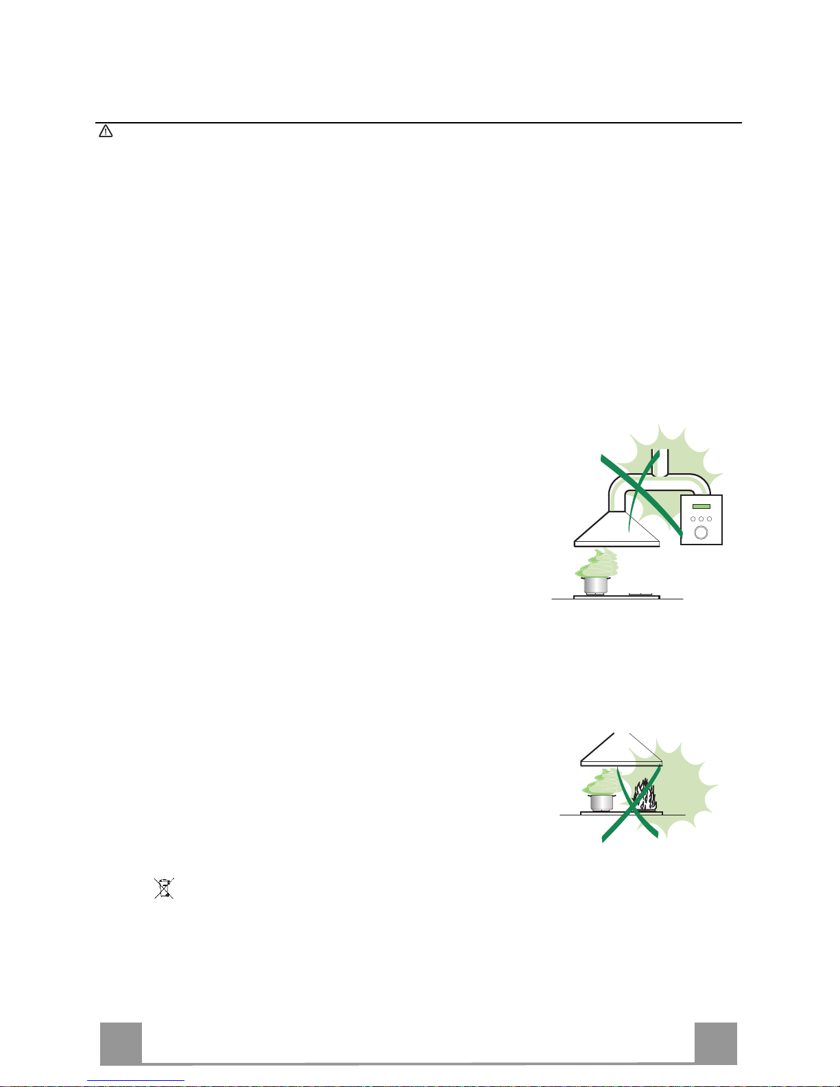
• Non collegare la Cappa a condotti di scarico dei fumi prodotti da combustione
(caldaie, c aminet t i, ec c.) .
• Nel caso in cui nella stanza vengano utilizzati sia la Cappa che apparecchi non
azionati da energia elettrica (ad esempio apparecchi utilizzatori di gas), si deve
provvedere ad una aerazione sufficiente dell’ambiente. Se la cucina ne fosse
sprovvista, praticare un’apertura che comunichi con l’esterno, per garantire il richiamo d’aria puli ta.
USO
• La Cappa è stata progettata esclusivamente per uso domestico, per abbattere gli
odori della cuc ina.
• Non fare mai uso impropr io del la Cap pa.
• Non lasciare fiamme li bere a f ort e int ens it à sott o la Cappa i n funz ione.
• Regolare sempre le fiamme in modo da evitare una evidente fuoriuscita laterale
delle stess e ri spet t o al fondo dell e p entol e.
• Controllare le fri ggit ric i durant e l’ us o: l ’ol io surr isc aldat o pot rebb e inf i ammars i.
• Non preparare aliment i f lambè s ot to l a c appa da cuc i na; per ic ol o d'inc en dio.
• Questo apparecchio non deve e ssere u tilizzato d a person e (bambin i inclusi) con
ridotte capacità psichiche, sensoriali o mentali, oppure da persone senza esperienza e conoscenza, a meno che non siano controllati o istruiti all’uso
dell’apparecchio da per son e r esponsabili della loro sicurezza.
• I bambini devono essere supervisionati per assicurarsi che non giochino con
l’apparecchi o.
MANUTENZIONE
• Prima di procedere a qualsiasi operazione di manutenzione, disinserire la Cappa
togliendo la spina elettric a o spegnendo l’interruttore generale.
• Effettuare una scrupolosa e tempestiva manutenzione dei Filtri secondo gli intervalli consigliati (Rischio di incendio).
• Per la pulizia d e lle su pe rfici d e lla C a ppa è suffi cie n te u tiliz za re u n pa nn o umido e
detersivo l iqui do neut ro.
Il simbolo sul prodotto o su lla confezione indica che il prodotto non de ve essere considerato
come un no r m ale rifiuto dom estico, ma dev e essere portato nel punto di raccolta appropr iato per
il rici cl aggi o di a ppar ecc hi at ur e el et tric he e d el ettr o nic he. Pr ov v edendo a smaltire questo prodotto in modo appropriato, si contribuisce a evitare potenziali conseguenze negative per l’ambiente
e per la salute, che potrebbero derivare da uno smaltimento inadeguato del prodotto. Per informazioni più dettagliate sul riciclaggio di questo prodotto, contattare l’ufficio comunale, il servizio
locale di smaltimento rif iut i o il negozio in cui è stato acqu istat o il prodot to .
Page 5
IT
5
5
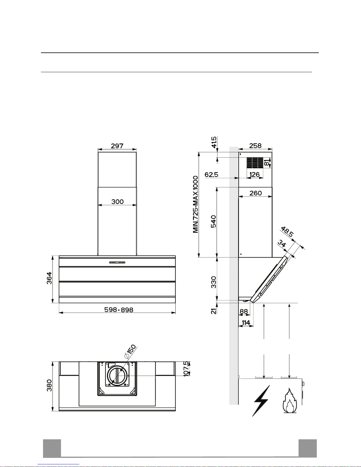
CARATTERISTICHE
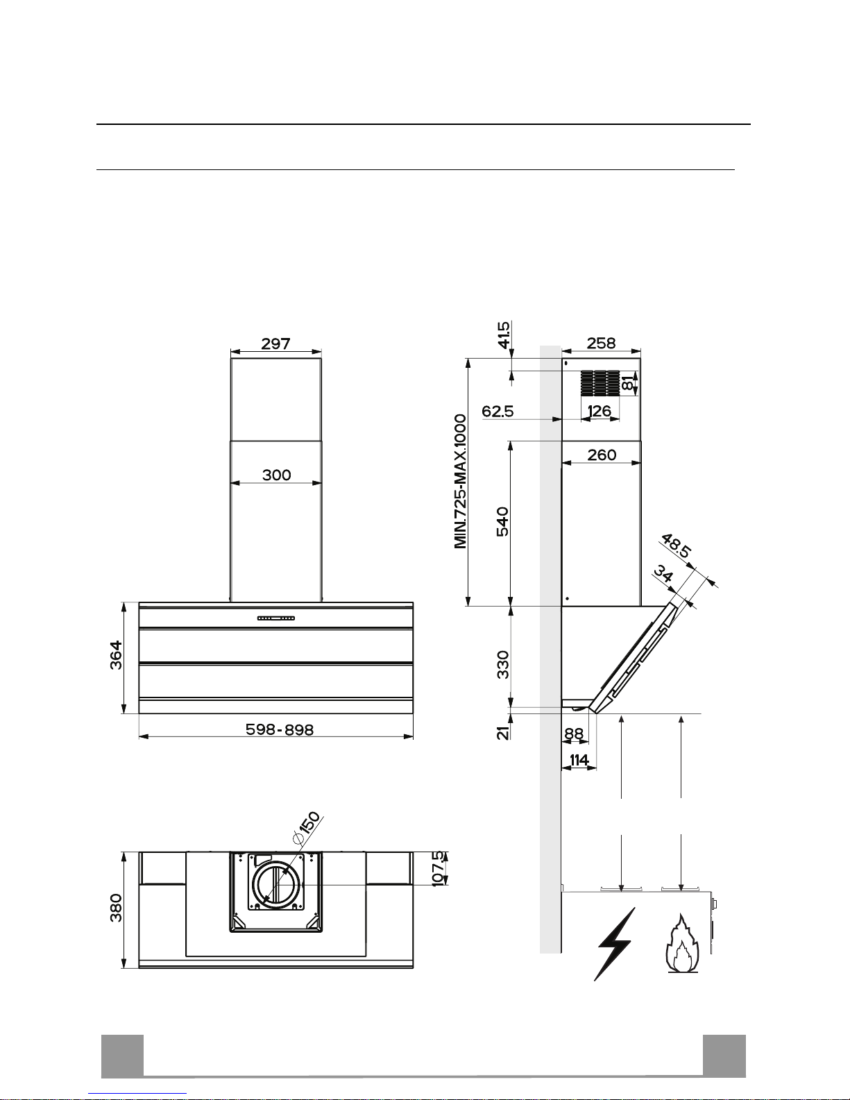
Ingombro
Min.
450mm
Min.
450mm
Page 6
IT
6
6
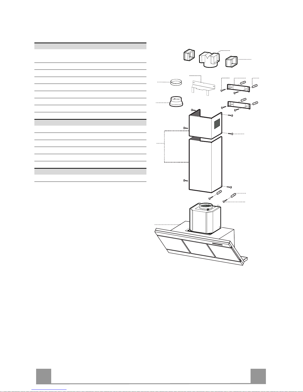
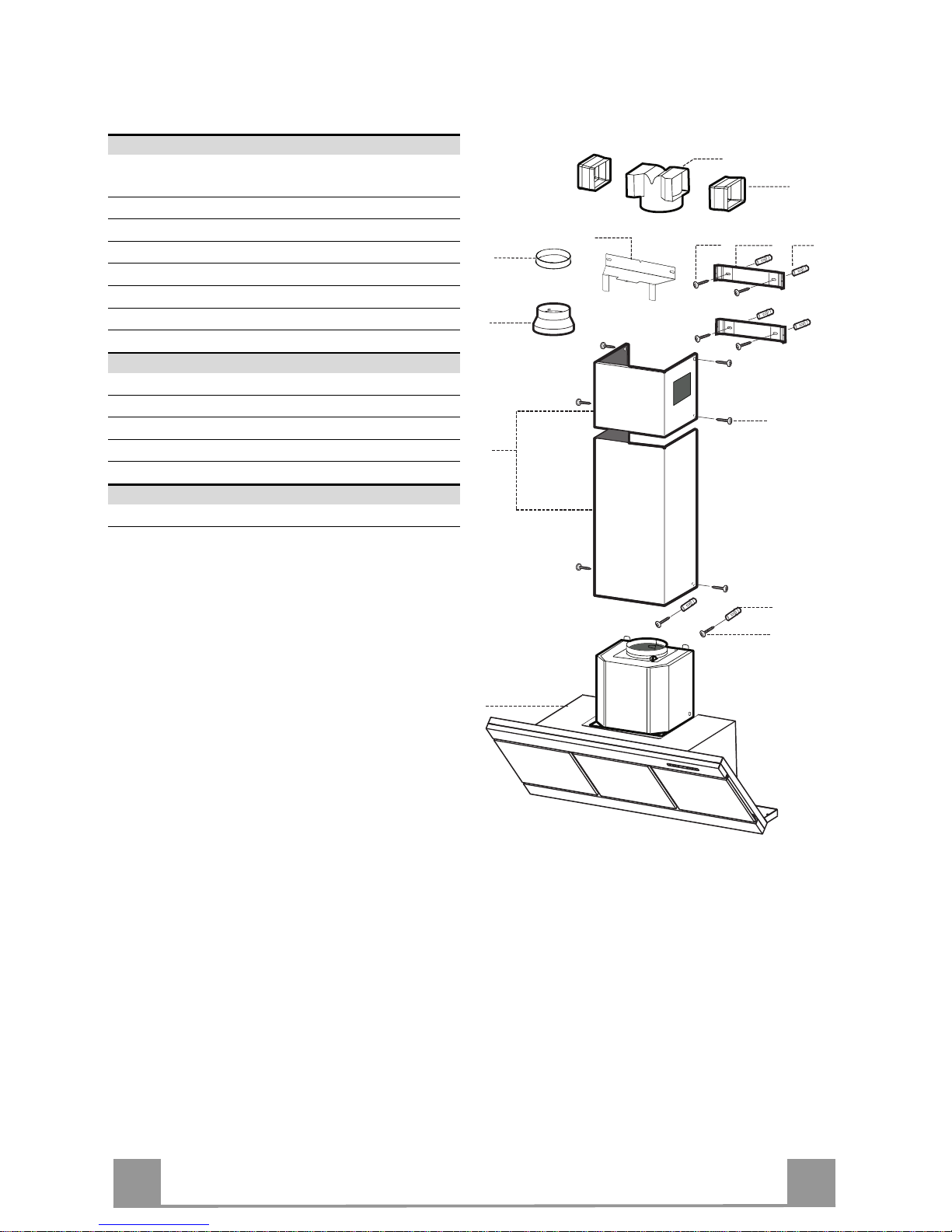
Componenti
Rif. Q.tà Comp onenti di Prodotto
1 1 Corpo Cappa completo d i: Comandi, Lu ce,
Gruppo Ventilatore, Filtri
2 1 Camino Telescopic o formato da:
2.1 1 Camino Superiore
2.2 1 Camino Inferiore
9 1 Flangia di Riduzio ne ø 150-1 20 mm
10 1 Anello di Maggiorazione ø 1 20-125 mm
14.1 2 Prolunga Raccord o Uscita Aria
15 1 Raccordo Uscita Aria
Rif. Q.tà Componenti di Installazione
7.2.1 2 Staffe Fi ss aggi o Camino Superi ore
7.3 1 Staffa Sostegno Raccordo
11 6 Tasselli
12a 6 Viti 4,2 x 44,4
12c 6 Viti 2,9 x 9,5
Q.tà Documentazione
1 Libretto Istruzioni
15
14.1
7.2.1
7.3
1112a
11
12a
12c
9
2
2.1
2.2
1
10
Page 7
IT
7
7
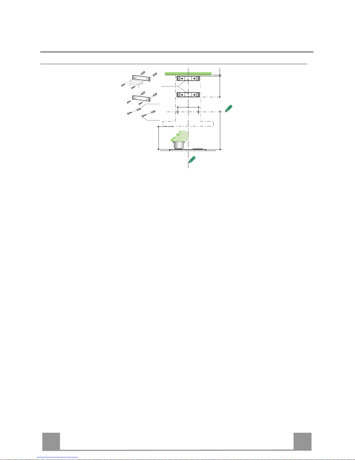
INSTALLAZIONE
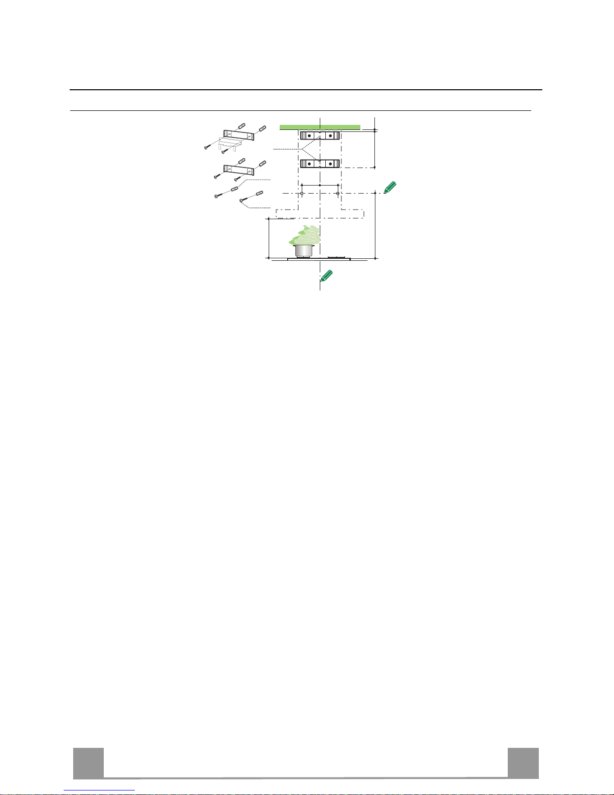
Foratura Parete e Fissaggio Staffe
7.2.1
11
12a
X
116
1÷2
116
1040
450 mm min
Tracciare sulla Parete:
• una linea Verticale fino al soffitto o al limite superiore, al centro della zona prevista per il montaggio della Cappa;
• una linea Orizzontale a: 1040 mm min. sopra il Piano di Cottura.
• Appoggi are come in dica to la St affa 7.2.1 a 1-2 mm dal soffitto o dal limite superiore, allineando
il suo centro (intagli) sulla linea Verticale di riferimento.
• Segnare i centri dei Fori della Staffa.
• Appoggiare come indicato la Staffa 7.2.1 a X mm sotto la prima staffa (X = altezza Camino Supe-
riore in dotazione), allineando il suo centro (intagli) sulla linea Verticale di riferimento.
• Segnare i centri dei Fori della Staffa.
• Segnare come indicato, un punto di riferim e nto a 116 mm dalla lin e a V e rticale d i riferimento.
• Ripetere questa operazione dalla parte opposta.
• Forare ø 8 mm i punti segnati.
• Inserire i tasselli 11 nei fori.
• Fissare la Staffa inferiore 7.2.1 utilizzando le Viti 12a (4,2 x 44,4 ) in dotazione.
• Fissare insieme la Staffa superiore 7.2.1 e la Staffa sostegno r accordo 7.3 utilizza ndo le 2 viti 12a
(4,2 x 44 ,4) in dotazione.
• Avvitare 2 Viti 12a (4,2 x 44,4 ) in dotaz ione nei fori p er il fiss aggio del cor po Cappa , lasciando
uno spazio di 5-6 mm fra la parete e l a testa della vite.
Page 8
IT
8
8
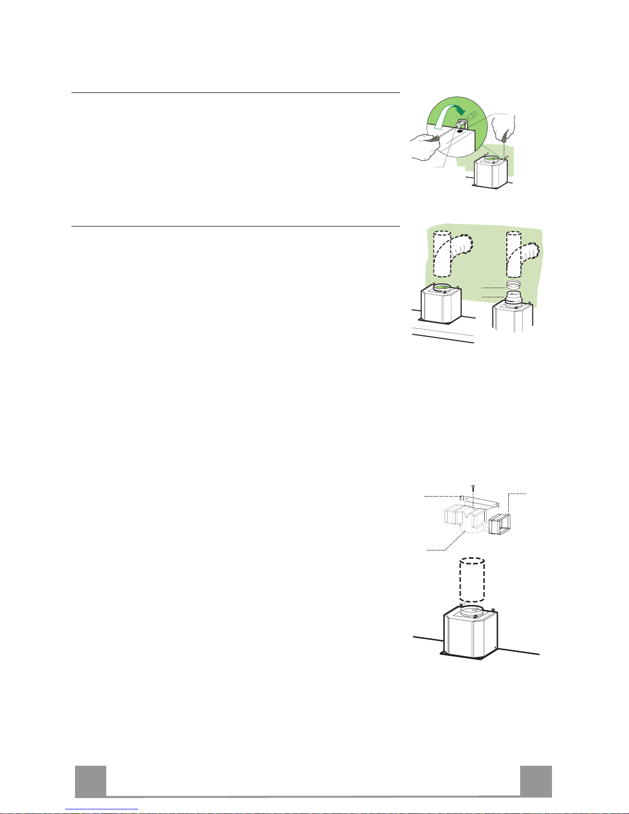
Montaggio Corpo Cappa
• Prima di agganciare il Corpo Cappa, serrare le 2 Viti Vr situate
sui punti di aggancio del Corpo Cappa.
• Agganciare il Corpo Cappa alle Viti 12a.
• Serrare definitivamente le Viti 12a di supporto.
• Agire sulle Viti Vr per livellare il Corpo Cappa.
12a
Vr
Connessioni
USCITA ARIA VERSIONE ASPIRANTE
Per installazione in Versione Aspirante collegare la Cappa alla
tubazione di uscita per mezzo di un tubo rigido o flessibile di
ø150 o 125 mm, la cui scelta è lasciata all'installatore.
• Per collegamento con tubo ø125 mm, inserire la Flangia di riduzione 9 sull’Uscita del Corpo Cappa e l’anello di maggiorazione 10 ø120-12 5 sulla Fla ng ia .
• Fissare il tubo con adeguate fascette stringitubo. Il materiale
occorrente non è i n dotazione.
• Togliere eventuali Filtri Antiodore al Carbone attivo.
9
ø 125ø 150
10
USCITA ARIA VERSIONE FILTRANTE
• Inserire lateralmente le Prol unghe Raccord o 14.1 sul Raccordo
15.
• Inserire il Raccordo 15 nella Staffa di Sostegno 7.3 fissandolo
con una Vite.
• Assicurarsi che l’uscita delle Prolunghe Raccordo 14.1 risulti
in corrispondenza delle bocchette del Camino sia in orizzontale
che in verticale.
• Collegare il Raccordo 15 all’Uscita del Corpo Cappa per mezzo di un tubo rigido o flessibile di ø150 mm, la cui scelta è lasciata all'installatore.
• Assicurarsi della presenza del Filtro Antiodore al Carbone attivo.
ø 150
15
14.1
7.3
Page 9
IT
9
9
CONNESSIONE ELETTRICA
• Collegare la Cappa all’Alimentazione di Rete interponendo un
Interruttore bipolare con apertura dei contatti di almeno 3 mm.
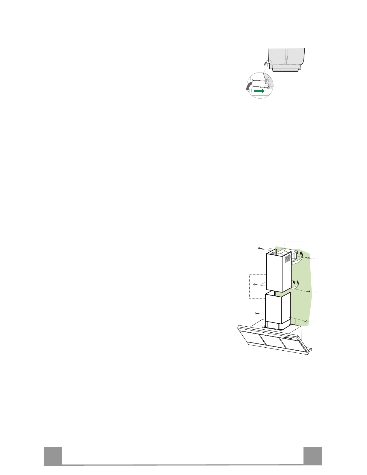
• Rimuovere i Filtri antigrasso (vedi par. “Manutenzione”) e assicurarsi che il connettore del Cavo di alimentazione sia correttamente inserito nella presa dell’Aspiratore
Montaggio Camino
Camino superiore
• Allargare leggermente le due falde laterali, agganciarle dietro
le Staffe 7.2.1 e richiuderle fino a battuta.
• Fissare lateralmente alle Staffe con 4 Viti 12c (2,9 x 9,5) in
dotazione.
• Assicurarsi ch e l ’ uscita delle Prolunghe Raccordo risulti in corrispondenza delle boc c hette de l C amino.
Camino inferiore
• Allargare leggermente le due falde laterali del Camino, agganciarle tra il Camino superi ore e la parete e richiuderle fino a
battuta.
• Fissare lateralmente la parte inferiore al Corpo Cappa, con 2
Viti 12c (2,9 x 9, 5) in dot azione.
7.2.1
12c
2
2.1
2.2
12c
12c
Page 10
IT 110
USO
B
A
D
C
E
G
F
I
H
L
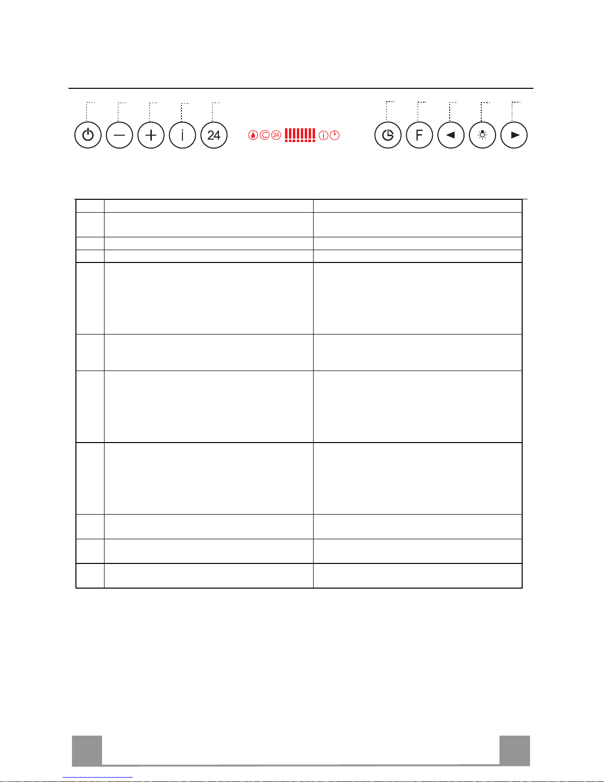
Quadro comandi
Tasto Funzione Display
A Accende e spegne il motore di aspirazione
all’ultima velocità utilizzata.
Visual izza la velocità impostata.
B Decrement a la velocità di esercizio. Diminuiscono i segmenti acces i.
C Incrementa la velocità di esercizio. Aumentano i segmenti accesi.
D Attiva la velocità intensiva da qualsiasi velo-
cità ad ecc ezione del Dela y e del 24H, tale velocità è temporizzata a 10 minuti, al termine
del tempo il sistema ritorna alla velocità precedentemente impostata. Adatta a fronteggiare le
massime emissioni di fumi di cottura.
Lampeggia I e i segmenti sul Display sono tutti
accesi.
Si disattiva premendo il Tasto.
E Attiva il motore ad una velocità che consente
un’aspira zione di 100 m
3
/h per 10 minuti ogni
ora, terminati il motore si ferma.
Visualizza 24 e i segmenti sul Display da tutti
accesi si spengono uno alla volta cicl icamente.
Si disattiva premendo il Tasto.
F Attiva lo spegnimento automatico ritardato di
30’. Adatto per completare l’eliminazione di
odori residui. Attivabile solo a motore acceso
ad una Velocità diversa da 24H e Intensiva, si
disattiva premendo il tasto o spegnendo il motore.
Visualizza il simb olo di un Orologio che lampeggia.
Si disattiva premendo il Tasto.
G Effettua il Reset dell’allarme sa turazion e Filtri
premendo il Tasto per circa 2 Secondi.
Dopo 100 ore di Funzionamento Visualizza il
simbolo Goccia per segnalare la saturazione
dei Filtri Metallici.
Dopo 200 ore di Funzionamento Visualizza C
per segnala re la sa tur azion e dei Filtr i al Ca rbone Attivo.
H Decrementa l’intensità di Illuminazione ad
ogni pres sione del Tasto in modo ciclico.
I Accende e spegne l’impianto di illuminazione
alla massima inten sità.
L Incrementa l’int ensità di Illumi nazione a d ogni
pressione del Tasto in modo ciclico.
Comando Blocco Tastiera: è possibile bloccare la tastiera, ad esempio per effettuare la pu lizia
della superficie in Vetro, quando la Cappa ha il Motore e le Luci spente.
Premendo per circa 5 Secondi il tasto F (Delay) si può abilitare o disabilitare il Blocco Tastiera
che è sempre confermato con un Beep e un’animazion e sulla barra motore del displ ay.
Page 11
IT 111
MANUTENZIONE
TELECOMANDO (OPZIONALE)
Questo apparecchio può essere comandato per mezzo di un telecomando, alimentato con pile alcaline zinco-carbone da 1,5 V del
tipo standard LR03-AAA.
• Non riporre il telecomando in prossimità di fonti di calore.
• Non disperdere le pile nell’ambiente, depositarle negli appositi
contenitori.
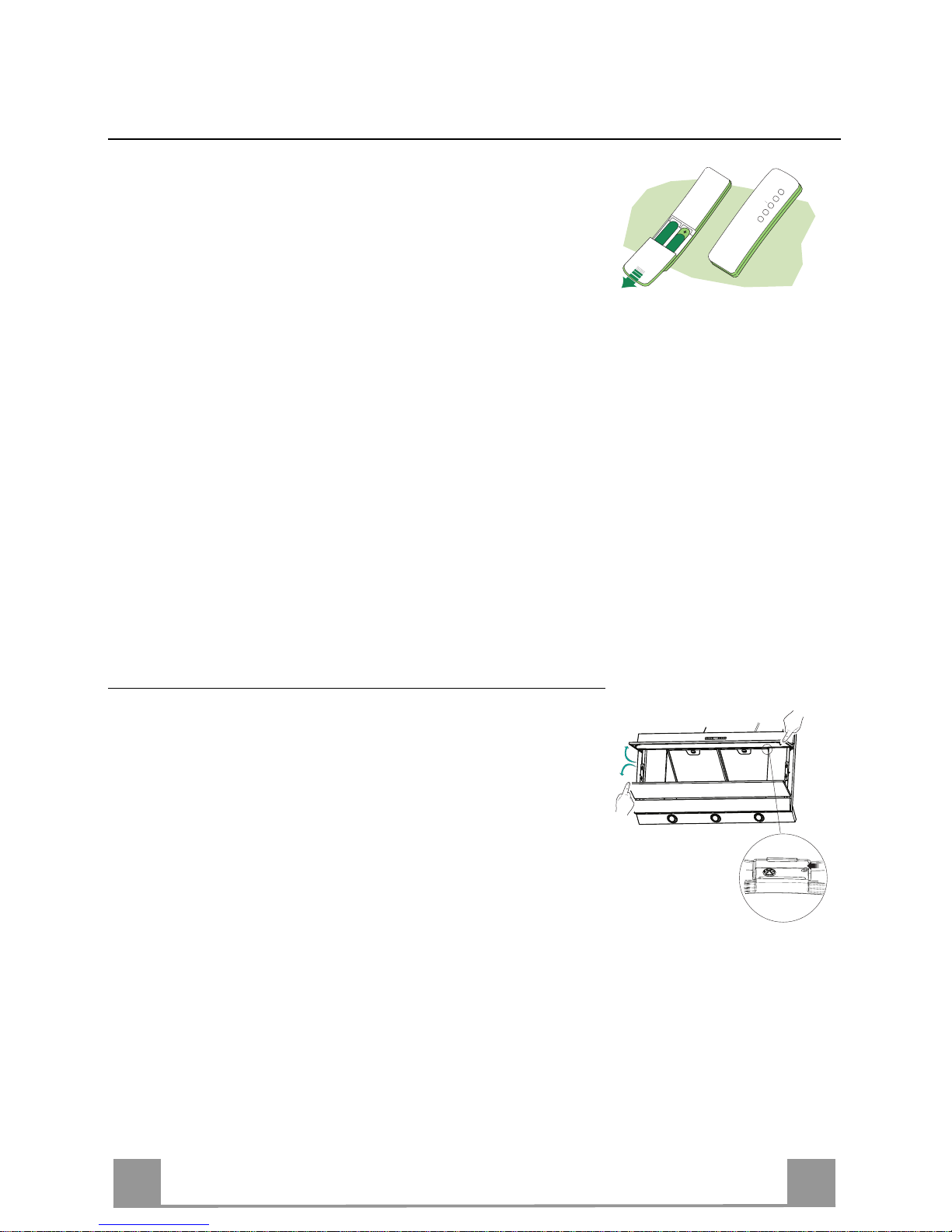
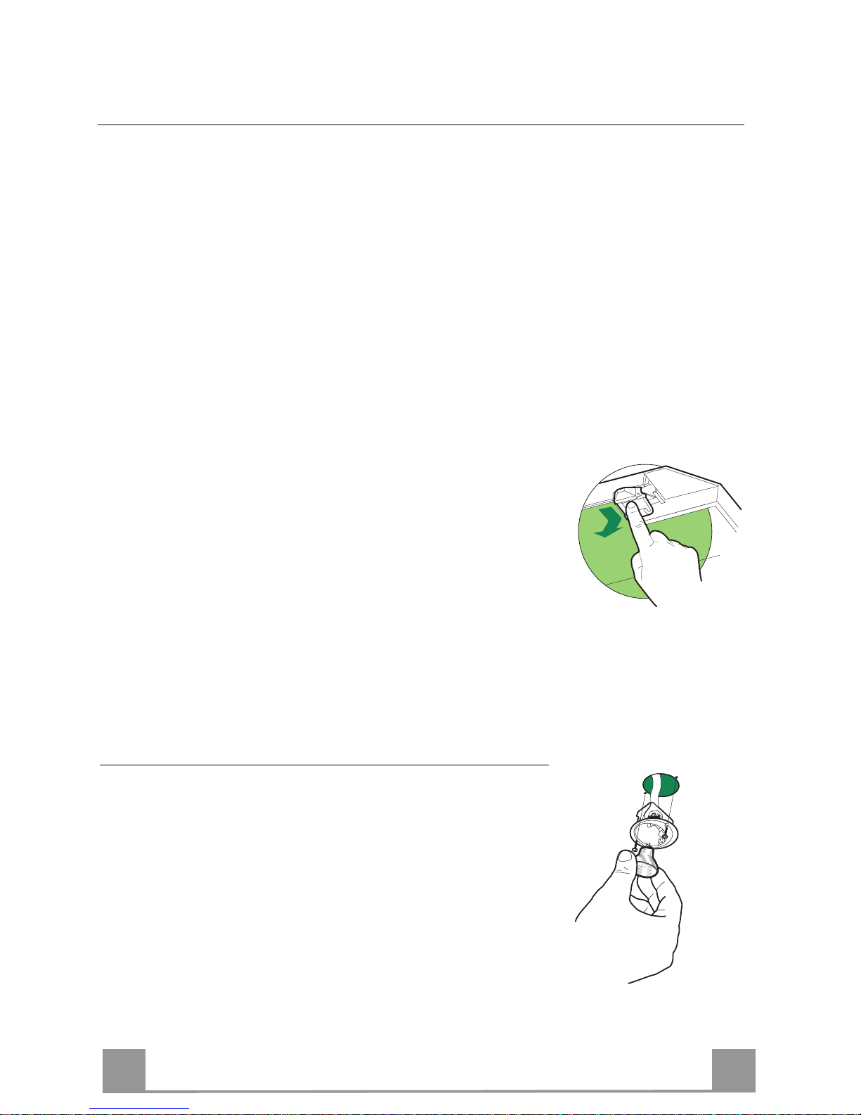
Pulizia dei Comfort Panel
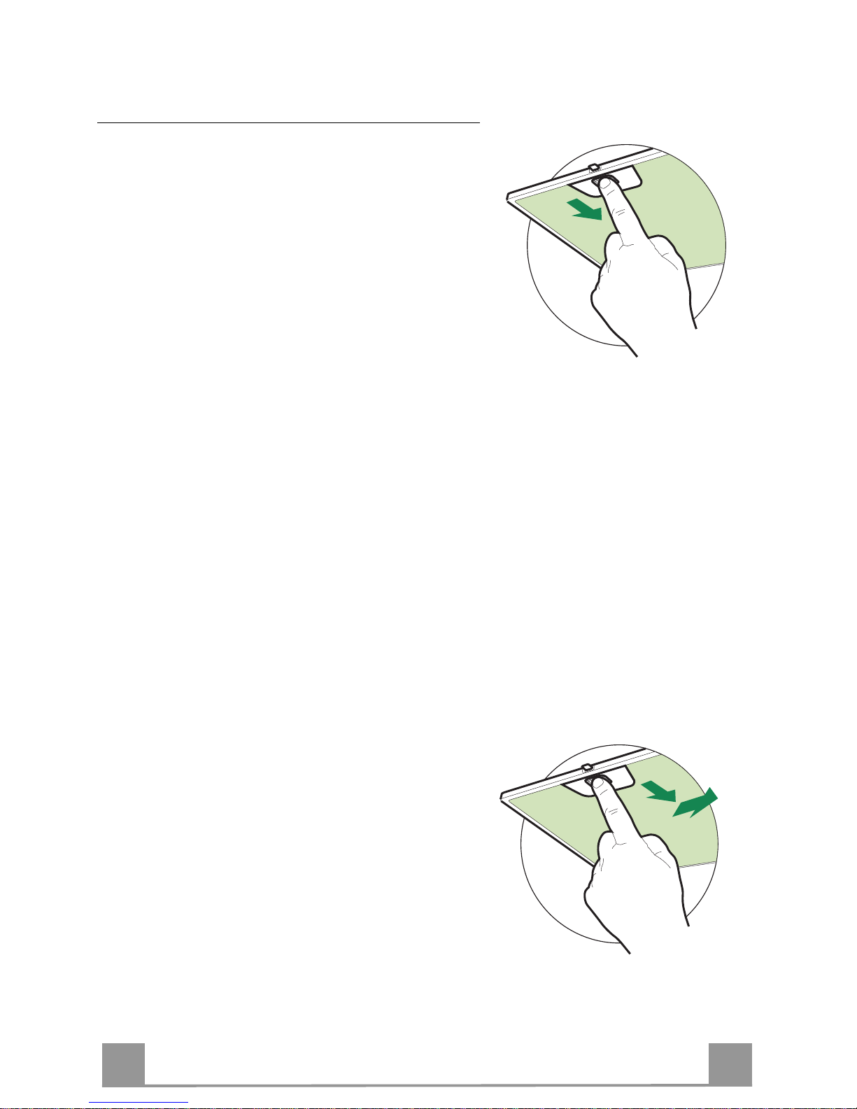
• Aprire il Comfort Panel tirandolo.
• Sganciare il pannello dal corpo cappa facendo scorrere
l’apposita leva del perno di fissaggio.
• Il comfort panel non va assolutamente lavato in lavastoviglie.
• Pulirlo esternamente con un panno umido e detersivo liquido
neutro.
• Pulirlo anche internamente utilizzando un panno umido e detergente neutro; non utilizzare panni o spugne bagnate, né getti
d’acqua; non utilizzare sostanze abrasive.
• Ad operazione ultimata riagganciare il pannello al corpo cappa
e richiuderlo.
.
Page 12
IT 112
Filtri antigrasso metallici
Sono lavabili anche in lavastoviglie, e necessitano di
essere lavati quando sul display appare il simbolo Goc-
cia o almeno ogni 2 mesi circa di utilizzo o più frequentemente, per un uso particolarmente intenso.
Reset del segnale di allarme
• Premere il tasto G per almeno 2 Secondi.
Pulizia Filtri
• Aprire il comfort panel.
• Togliere i Filtri uno alla volta, spingendoli verso la
parte posteriore del gruppo e tirando contemporaneamente verso il basso.
• Lavare i Filtri evitando di piegarli, e lasciarli asciugare prima di rimontarli. (Un’eventuale cambiamento
del colore della superficie del filtro, che potrebbe verificarsi nel tempo, non pregiudica assolutamente
l’efficienza dello stesso.)
• Rimontarli facendo attenzione a mantenere la maniglia verso la parte visibile esterna.
• Richiudere il comfort panel.
ATTENZIONE: Per la Versione da 60 Cm, togliere i
Filtri uno alla volta, spingendoli verso la parte posteriore del gruppo tirando contemporaneamente verso il basso e successivamente verso il centro della Cappa.
Page 13
IT 113
Filtri antiodore al Carbone attivo (Versione Filtrante)
Non è lavabile e non è rigenerabile, va sostituito quando sul display appare il simbolo C o almeno ogni 4 mesi. La segnalazione di Allarme va preventivamente attivata.
Attivazione del segnale di allarme
• Nelle Cappe in Versione Filtrante, la segnalazione di Allarme saturazione Filtri va attivata al
momento dell’installazione o successivamente.
• Spegnere l e Lu ci e il Motore di aspirazione.
• Premere il tasto E per circa 5 Sec . fino all’accension e degli ultimi due segmenti e di tutta la
linea puntinata della barra Motore sul Display.
• Rilasciare il tasto E, l’icona “Orologio” inizia a lampeggiare.
• Entro 3 seco ndi pr emere il Tasto D per abilitazione / disabilitazione Filtri C.A.
• Accensione del simbolo C Allarme saturazione Filtro C.A. ATTIVATO
• Spegnimento del simbolo C Allarme saturazione Filtro C.A. DISATTIVATO
SOSTITUZIONE FILTRO ANTIODORE AL CARBONE ATTIVO
Reset del segnale di allarme
• Spegnere l e Lu ci e il Motore di aspirazione.
• Premere il tasto G per almeno 2 Secondi.
Sostituzione Filtro
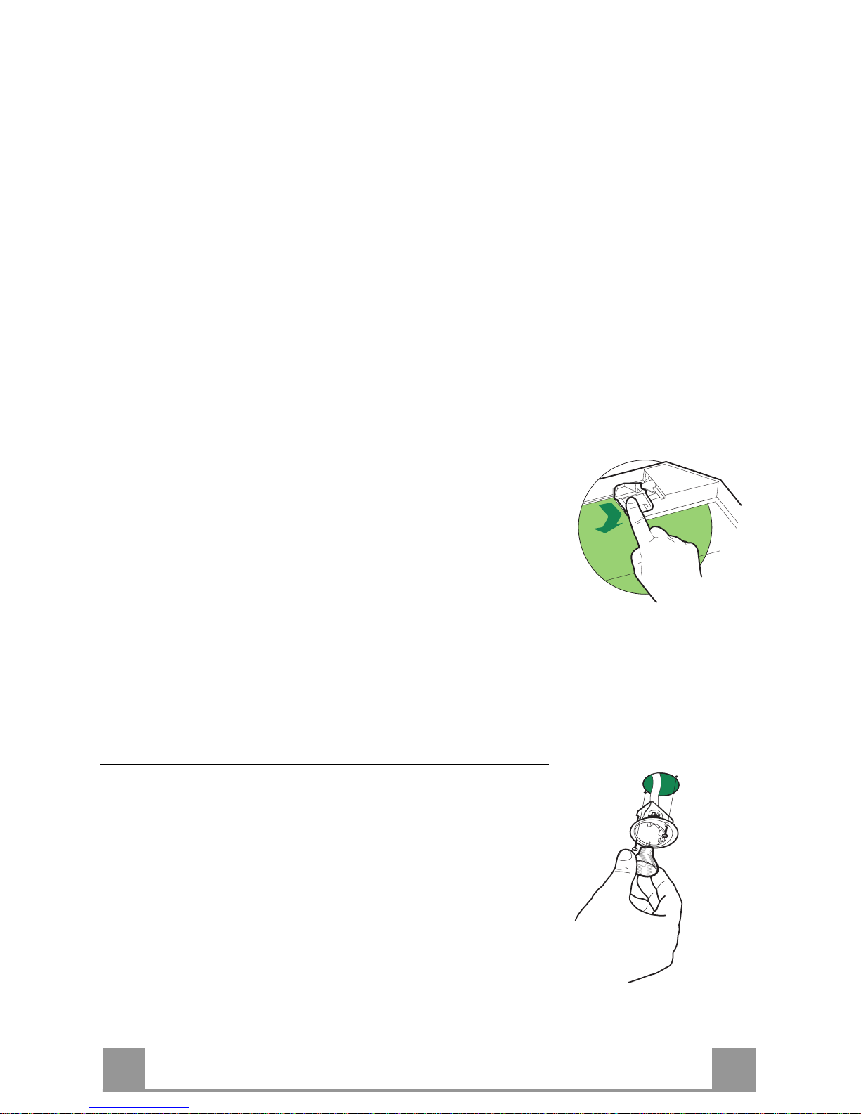
• Aprire il comfort panel.
• Togliere i Filtri antigrasso metallici.
• Rimuovere il Filtro antiodore al Carbone attivo saturo, come
indicato in figura.
• Montare il nuovo Filtro agganciandolo nella sua sede.
• Rimontare i Filtri antigrasso metallici.
Illuminazione
SOSTITUZIONE LAMPADE
Lampade alogene d a 20 W.
• Togliere le due viti che fissano il Supporto illuminazione e sfilarlo dalla Cappa.
• Estrarre la Lampada dal Supporto.
• Sostituirla con una nuova di uguali caratteristiche, facendo attenzione di inserire correttamente i due spinotti nella sede del
Supporto.
• Rimontare il Supporto fissandola con le due Viti precedentemente tolte.
Page 14
EN
114
RECOMMENDATIONS AND SUGGESTIONS
The Instructi ons
for Use appl y to s everal versi ons of this a pplianc e. Ac cor
d-
ingly, you may find descriptions of in dividual features th at do not apply to
your specific appliance.
INSTALLATION
• The manuf acturer will not be hel d liable for any dama ges resulting from incorrect or i mpr op er in s tal lat ion .
• The minimum safety distance between the cooker top and the extractor
hood is 650 m m (som e m od el s c an be installed at a lower height, plea se re fer to the paragraphs on working dimensions and installation).
• Check that the mains voltage corresponds to that indicated on the rating
plate fixed to the inside of the hood.
• F or Class I appliances, check th at the domestic power suppl y guarantees
adequate earthing.
Connect the extr actor t o the exh aust fl ue thr ough a pi pe of minim um di ame-
ter 120 mm. The route of the flue must be as short as possible.
• Do not connect the extractor hood to exhaust ducts carrying combustion
fumes (boilers, fireplaces, etc.).
• If the extractor is us ed in conjunctio n with non-elec tric al a ppliances (e. g. g as
burning appl iances), a s ufficient degree of aeration mu st be guarant eed in
the room in orde r to preve nt the bac kflow of ex haust gas . The kit chen mus t
have an opening communicating directly with the open air in order to
guarantee the entry of clean air.
USE
• The extractor hood has been designed exclusively for domestic use to eliminate kitchen smells.
• Never use the hood for purposes other than for which it has been designed.
• Never le a ve high na ke d fla me s un de r the ho od wh en it i s in op er at ion .
• Adjust the flame in te nsity to direct i t o nto the bo ttom o f the pan only, m aking
sure that it does not engulf the sides.
• Deep fat f ryers must be conti nuously monit ored during use: overheated oil
can burst into flames.
• Do not flambè under the range hood; risk of fire
• This appli ance is not intende d for use by person s (including chil dren) with
reduced physi cal, sensory or m ental capabi lities, or lack o f experience an d
knowledge, unl ess th ey have be en gi ven su pervisi on o r instr uction conce rning use of the appliance by a person responsible for their safety.
• Children should be s up ervised to ens ur e that they do not pl a y wi th t he ap pl i ance.
MAINTENANCE
• Switch off or unplug t he a ppliance from the m ains supply befo re ca rr ying out
any maintenance work.
• Clean and/or replace the Filters after the specified time period (Fire hazard).
• Clean the hood using a damp cloth and a neutral liquid detergent.
The symbol on the product or on its packaging indicates that this product may not be treated
as household waste. Instead it shall be handed over to the applicable collection point for the
recycling of el ec tr i cal and electro ni c eq uipmen t. By ensuring this product i s di s p osed of correctl y ,
you will help prevent potential negative consequences for the environment and human health,
which could otherwise be caused by inappropriate waste handling of this product. For more
detailed information about recycling of this product, please contact your local city office, your
household waste disposal service or the shop where you purchased the product.
Page 15
EN
115
CHARACTERISTICS
Dimensions
Min.
450mm
Min.
450mm
Page 16
EN
116
Components
Ref. Q.ty Product Components
1 1 Hood Body, complete with: Controls, Light,
Blower, Fil ters
2 1 Telescopic Chimney comprising:
2.1 1 Upper Section
2.2 1 Lower Section
9 1 Reducer Flange ø 150-120 mm
10 1 Adapting ring ø 12 0-125 mm
14.1 2 Air Outlet Connec tion Extens ion
15 1 Air Outlet Connection
Ref. Q.ty Installation Components
7.2.1 2 Upper Chimney Section Fixing Brackets
7.3 1 Air Outlet Connection Supp ort
11 6 Wall Plugs
12a 6 Screws 4,2 x 44,4
12c 6 Screws 2,9 x 9,5
Q.ty Documentation
1 Instruction Manual
15
14.1
7.2.1
7.3
1112a
11
12a
12c
9
2
2.1
2.2
1
10
Page 17
EN
117
INSTALLATION
Wall drilling and bracket fixing
7.2.1
11
12a
X
116
1÷2
116
1040
450 mm min
Wall marking:
• Draw a vertical line on the supporting wall up to the ceiling, or as high as practical, at the
centre of the area in which the hood will be installed.
• Draw a horizontal line at 1040 mm above the hob.
• Place bracket 7.2.1 on the wall as shown about 1-2 mm from the ceiling or upper limit align-
ing the centre (n otch) with the verti cal reference line.
• Mark the wall at the centres of the h oles in the bracket.
• Place bracket 7.2.1 on the wall as shown at X mm below the first bracket (X = height of the
upper chimney section supplied), aligning the centre (notch) with the vertical line.
• Mark the wall at the centres of the holes in the bracket .
• Mark a re ference point as indicated at 116 mm from the vertical re ference.
• Repeat this operation on the other side.
• Drill ø 8 mm holes at all the centre points marked.
• Insert the wall plugs 11 in the holes.
• Fix t he lower bracket 7.2.1 by using the 12a screws (4,2 x 44,4) supplied.
• Fix the upper bracket 7.2.1 and the air outlet connection support 7.3 togeth er using the 2
screws 12a (4,2 x 44,4) supplied.
• Insert the two screws 12a (4,2 x 44,4) supplied in the hood body fixing holes, leaving a gap
of 5-6 mm between the wall and the head of the screw.
Page 18

EN
118
Mounting the hood body
• Before attaching the hood body, tighten the two screws Vr located on the hood body mounting points.
• Hook the hood body onto the screws 12a.
• Fully tighten the support screws 12a.
• Adjust the screws Vr to level the hood body.
12a
Vr
Connections
DUCTED VERSION AIR EXHAUST SYSTEM
When installing the ducted version, connect the hood to the
chimney using either a flexible or rigid pipe ø 150 or 125 mm,
the choice of which is left to the installer.
• To install a ø 125 mm air exhaust connection, insert the reducer flange 9 on the hood body air outlet and the adapting
ring ø120-125 10 on the reducer flange.
• Fix the pipe in position using sufficient pipe clamps (not supplied).
• Remove an y activated charcoal fil t ers.
9
ø 125ø 150
10
RECIRCULATION VERSION AIR OUTLET
• Insert the conn ection exten sion pieces laterall y 14.1 in connection 15.
• Insert the Co nnector 15 into t he Support bracket 7.3 and fix it
with a screw.
• Make sure that the out let of the extension pieces 14.1 is horizontally and vertically aligned with the chimney outlets.
• Connect the air outlet connection 15 to the hood body outlet
using either a flexible or rigid pipe ø 150 mm, the choice of
which is left to the installer.
• Ensure that the activated charcoal filters have been inserted.
ø 150
15
14.1
7.3
Page 19

EN
119
ELECTRICAL CONNECTION
• Connect the hood to the mains through a two-pole switch having a contact gap of at least 3 mm.
• Remove the grease filters (see paragraph Maintenance) being
sure that the connector of the feeding cable is correctly inserted
in the socket placed on the side of the fan.
Flue assembly
Upper exhaust flue
• Slightly widen the two sides of the upper flue and hook them
behind the brackets 7.2.1, making sure that they are well
seated.
• Secure the sides to the brackets by using the 4 screws 12c (2,9
x 9,5) supplied.
• Make su re t hat the outlet o f the extensions pieces is aligned
with the chimney outlets.
Lower exhaust fl ue
• Slightly widen the two sides of the flue and hook them between the upper flue and the wall, making sure that they are
well seated.
• Fix the lower part laterally to the hood body by using the 2
screws 12c (2,9 x 9,5) supplied.
7.2.1
12c
2
2.1
2.2
12c
12c
Page 20

EN
220
USE
B
A
D
C
E
G
F
I
H
L
Control board
Key Function Display
A
Switches the extractor motor on and off at the latest
selected speed
Indicates the selected speed.
B Decreases the suction speed. The numb er of lit LEDS d ecreases.
C Increases t he suct ion speed. The number of lit LEDS increases.
D By pressing this key it is possible to start the inten-
sive speed from any previously selected speed except the Delay-function and 24H-function. This
speed has been timed at 10 minutes. After that time
the system activates automatically the latest selected
speed. This function is suitable for cooking conditions when vapours and smells are at the utmost emission.
I flashes and the LEDS are a ll lit.
By pressing the key the function is
stopped.
E Starts the motor at a speed that allows a suction of
100 m
3
/h for 10 minutes every hour, after which the
motor stops.
24 appears and the LEDS extingui sh one
by one.
By pressing the key the function is
stopped
F By pressing this key it is possible to set the delayed
shutdown of the motor and the lighting to 30 minutes. This function is suitable for a complete elimination of resi dual cookin g odours. Fun ctionin g only
when the mot or is on(n ot durin g th e 24H-fu ncti on or
intensive function). By pressing the key the function
is stopped
A flashing clock-symbol appears.
By pressing the key the function is
stopped
G By pressing this key for about 2 seconds it is possi-
ble to reset the filter saturation alarm
After 100 working hours a drop-symbol
appears. Metal grease filters have to be
washed.
After 200 working hours C appears.
Charcoal filters have to replaced.
H By pressing this key the intensity of the lighting
system can be decreased.
I Switches on/ off th e lightin g system at th e maximu m
intensity.
L By pressing this key the intensity of the lighting
system can be increased.
Keyboard lock: it i s possible to jam the keyboard when, for exampl e, cleaning the glass. The
motor and lights are switched off.
By pressing the F-key (Delay) for about 5 seconds the keyboard block can be activated or deactivated. This function is confirmed by a Beep and by moving motor LEDS on display.
Page 21

EN
221
MAINTENANCE
REMOTE CONTROL (OPTIONAL)
The appliance can be controlled using a remote control powered
by a 1.5 V carbon-zinc alkaline batteries of the standard LR03AAA type.
• Do not place the remote contro l near to heat sources.
• Used batteries must be disposed of in the proper manner.
Cleaning the Comfort Panels
• Pull the Comfort Panel to open it.
• Disconnect the panel from the hood canopy by sliding the fixing pin lever.
• The comfort panel must never be washed in a dishwasher.
• Clean the outside by using a damp cloth and neutral liquid detergent.
• Clean the inside as well by using a damp cloth and neutral detergent; do not use wet cloths or sponges, or jets of water; do
not use abrasive substances.
• When the above operation has been completed, hook the panel
back to the hood canopy and close it by turning the knob in the
opposite direction .
Page 22

EN
222
Metal grease filters
Metal filters can be washed also in a dish machine.
They need to be wash ed every ti me a drop-symbol appears in the disp lay or at l east ev ery two mon ths. In case of very frequent use these have to be washed even
more often.
Alarm reset
• Press the G-key for at least 2 seconds.
Cleaning
• Open the comfort panel.
• Remove the filters one by one by pushing them
backwards and pulling them down contemporaneously.
• Wash the filters. Pay attention not to bend them.
Make sure that filters are completely dry before putting them into their seat. (a possible modification of
the filter surface doesn’t influence its efficiency).
• Place the filters again into their seats and make sure
that the handle of the filter remains outside.
• Close the comfort panel.
ATTENTION: Remove the filters one by one by pushing them towards the back side of the hood an d simultaneously by pulling downwards and towards the centre
of the hood (only in case of 60 cm hood version).
Page 23
EN
223
Charcoal filter (recycling version)
This filter cannot be washed or regenerated. It must be replaced when the C appears on the
display or at least once every 4 months. The filter saturation alarm has to be activated already
before.
Activation of the alar m signal
• In the recycling version hoods the filter saturation alarm must be activated during the installation or later.
• Switch off the hood and the lights.
• Press the E-key for about 5 seconds until the last two segments of the motor LEDS are lit on
the display.
• By releasing the E-key the clock icon starts to flash.
• Within 3 seconds press the D-key to activate/deactivate charcoal filter saturat ion alarm.
• C-symbol lit - charcoal filter saturation alarm ACTIVATED.
• C-symbol unlit - charcoal filter saturation alarm DEACTIVATED.
SUBSTITUTION OF THE CHARCOAL FILTER
Alarm reset
• Switch off the motor and the lighting system.
• Press the G-key for at least 2 seconds.
Substitution of the filter
• Open the confort panel.
• Remove the metal grease filters.
• Remove the charcoal filter as indicated in the picture.
• Place th e filter again into its seat.
• Place again th e metal grease filters into their place.
Lighting
LIGHT REPLACEMENT
20 W halogen light.
• Remove the 2 screws fixing the Lighting support, and pull it
out of from the Hood.
• Extract the lamp from the Support.
• Replace with another of the same type, making sure that the
two pins are properly inserted in the lamp holder socket holes.
• Refit the Support, fixing it in place with the two screws removed as above.
Page 24

FR
224
CONSEILS ET SUGGESTIONS
La présente notice d'emploi vaut pour plusieurs versions de l'appareil. Elle peut conte-
nir des descriptions d'access oir es ne fi gurant pas dan s vot re apparei l.
INSTALLATION
• Le fabricant décline toute responsabilité en cas d e domm age dû à un e in sta llatio n n on
correcte ou non conforme aux règl es d e l’ art.
• La distance minimale de sécurité entre le plan de cuisson et la hotte doit être de 650
mm au moins (certains modèles peuvent être installés à une hauteur inférieure : se reporter aux paragraphe s « Encombrem ent » et « Instal lati on »).
• Vérifier que la tension du secteur correspond à la valeur qui figure sur la plaquette
apposée à l’intérieur de la hotte.
• Pour les Appareils appartenant à la Ière Classe, veiller à ce que la mise à la terre de
l’installation électrique domestique ait été effectuée conformément aux normes en vigueur.
• Connecter la hotte à la sor tie d’air aspiré à l’aide d’une tuyauterie d’un diamètr e égal ou
supérieur à 120 mm. Le parcours de l a tuyaut eri e doit être le plus court possibl e.
• Ne pas connecter la hotte à des conduites d’évacuation de fumées issues d’une combustion tel que (Chaudi ère, chemi née, et c…).
• Si vous utilisez des appareils qui ne f oncti onnent pas à l’électricité dans l a pièce ou est
installée la hotte (par exemple: des appareils fonctionnant au gaz), vous devez prévoir
une aération suffisante du milieu. Si la cuisine en est dépourvue, pratiquez une ouverture qui communique avec l ’ext éri eur pour gar anti r l’inf iltr ation de l’ai r pur.
UTILISATION
• La hotte a été conçue exclusivement pour l’usage domestique, dans le but d’éliminer
les odeurs de la cuisine.
• Ne jamais utiliser abusi vement l a hot te.
• Ne pas laisser les flammes li bres à forte intensi té quand l a hott e est en servi ce.
• Toujours régler les flammes de manière à éviter toute sortie latérale de ces dernières
par rapport au fond des marmit es.
• Contrôler les frit euses lors de l ’ utilisat ion car l’huile sur chauff ée pourrai t s’ enfl ammer.
• Ne pas préparer d’aliment s fl ambés sous la hot te de cui sine : ri sque d’i ncendi e
• Cet appareil ne doit pas être utilisé par des personnes (y compris les enfants) ayant
des capacités psychiques, sensorielles ou mentales réduites, ni par des personnes
n’ayant pas l’expérience et la connaissan ce de ce type d’apparei l s , à moins d'être sous
le contrôle et la formati on de personn es respo nsables de l eur sécuri té.
• Les enfants doivent être surveillés pour s'assurer qu'ils ne jouent pas avec l'appareil.
ENTRETIEN
• Avant de procéder à toute op ération d’entretien, retirer l a hotte en retirant la fiche ou en
actionnant l’interrupteur général.
• Effectuer un entretien scrupuleux et en temps dû des Filtres, à la cadence conseillée
(Risque d’incendie) .
• Pour le nettoyage des surfaces de la hotte, il suffit d’utiliser un chiffon humide et détersif liquide neutre.
Le symbole sur le produit ou son emballage indique que ce produit ne peut être traité comme
déchet ménager. Il doit plutôt être remis au point de ramassage concerné, se chargeant du recyclage du matériel électrique et électronique. En vous assurant que ce produit est éliminé correctement, vous favorisez la prévention des conséquences négatives pour l’environnement et la santé
humaine qui, sinon, seraient le résultat d’un traitement inapproprié des déchets de ce produit. Pour
obtenir plus de détails sur le recyclage de ce produit, veuillez prendre contact avec le bureau municipal de votre région, votre service d’élimination des déchets ménagers ou le magasin où vous avez
acheté le produit.
Page 25

FR
225
CARACTERISTIQUES
Encombrement
Min.
450mm
Min.
450mm
Page 26

FR
226
Composants
Réf. Q.té Composants de Produit
1 1 Corps Hotte équipé de:Comandes, Lu-
mière,Groupe Ventilateur,Filtres
2 1 Cheminée Télescopique formée de :
2.1 1 Cheminée Supérieure
2.2 1 Cheminée Inférieure
9 1 Flasque de Réduction ø 150-12 0 mm
10 1 Anneau de raccord Ø 120 - 125 m m
14.1 2 Rallonge Raccord Sortie Air
15 1 Raccord Sortie Air
Réf. Q.té Composants pour l ’installation
7.2.1 2 Brides Fix ati on Ch emi né e Supér ie ur e
7.3 1 Bride Support Raccor d
11 6 Chevilles
12a 6 Vis 4,2 x 44,4
12c 6 Vis 2,9 x 9,5
Q.té Documentation
1 Manuel d’instructions
15
14.1
7.2.1
7.3
1112a
11
12a
12c
9
2
2.1
2.2
1
10
Page 27

FR
227
INSTALLATION
Perçage Paroi et Fixation Brides
7.2.1
11
12a
X
116
1÷2
116
1040
450 mm min
Tracer sur la paroi:
• une ligne verticale allant jusqu’au plafond ou à la limite supérieure, au centre de la zone
prévue pour le montage de la hotte;
• une ligne horizontale à 1040 mm min. au-dessus du plan de cuisson.
• Poser comme indiqu é une br ide 7.2.1 sur la paroi à 1-2 mm du plafond ou de la limite supérieure, en alignant son centre (découpes) sur la ligne verticale de repère.
• Marquer les centres des trous rainurés de la bride.
• Poser comme indiqué la bride 7.2.1 à X mm sous la première bride (X = hauteur cheminée
supérieure fournie), en alignant son cent r e (découpes) sur la ligne vertical e de repère.
• Marquer les centres des trous rainurés de la bride.
• Marquer comme indiqué, un point de référence à 116 mm de la ligne verticale de repère.
• Répéter cette opération sur le côté opposé.
• Percer de ø 8 mm tous les points marqués.
• Insérer les chevilles 11 dans les trous.
• Fixer la bride inférieure 7.2.1 en utilisant les vis 12a (4,2 x 44,4) fournies.
• Fixer ensemble la bride supérieure 7.2.1 et le support 7.3 en utilisant les vis 12a (4,2 x 44,4)
fournies.
• Visser les 2 vis 12a (4,2 x 44,4) fournies dans les trous de fixation du corps hotte, en laissant
un espace de 5-6 mm entre le mur et l a t ête de la vis.
Page 28

FR
228
Montage Corps Hotte
• Avant d’accrocher le corp s hotte, serrer les deux vis Vr situées
sur les points d’accro chage du corps hotte.
• Accroch er l e corps hotte aux vis 12a prévues à cet effet.
• Serrer définitivement les vis 12a de support.
• Agir sur les vis Vr pour niveler le corps hotte.
12a
Vr
Connexions
SORTIE DE L'AIR EN VERSION EVACUATION
Pour l’installation dans la Version Aspirante, connecter la hotte au tuyau
d’évacuation, au moyen d’un tuyau rigide ou flexible de ø 150 ou 125
mm, que l’installateur pourra choisir à son propre gré.
• Pour raccord de ø 125 mm, insérer la bride de réduction 9 sur la sortie
du corps de hotte et l’anneau d’agrandissement 10 de ø 120-125 mm
sur la bride.
• Fixer le tuyau à l’aide du collet serre-tuyaux. Le matériel nécessaire
n'est pas fourni avec l'appareil.
• Retirer les filtres anti-odeur au charbon actif, s’ils sont montés.
9
ø 125ø 150
10
SORTIE AIR VERSION FILTRANTE
• Insérer latéralement les rallonges raccord 14.1 sur le raccord
15.
• Placer le raccord 15 dans l’étrier de soutien 7.3 en le fixant
avec une vis.
• S’assurer que la so rtie des rallonges racco rd 14.1 se trouve au
niveau des bouches de la cheminée aussi bien en horizontal
qu’en vertical.
• Brancher l e raccord 15 à la sortie du corps de la hotte avec un
tube rigide ou flexible de ø 150 mm, selon le choix de
l’installateur.
• S’assurer de la présence des filtres anti-odeur au charbon actif.
ø 150
15
14.1
7.3
Page 29

FR
229
BRANCHEMENT ELECTRIQUE
• Bran cher la hotte sur le secteur en interposant un interrupteur
bipolaire avec ouverture des contacts d’au moins 3 mm.
• Enlever les filtres à graisse (voir § "Entretien") et s'assurer que
le connecteur du câbl e d'al imentati on so it bien bran ché dan s la
prise du diffuseur.
Montage Cheminée
Cheminée supérieure
• Elargir légère ment les deux bords latériau x, et les accrocher
derrières les brides 7.2.1 ; refermer
jusqu’à la butée.
• Fixer latéralement aux brides à l’aide des 4 vis
12c fournies.
• S’assurer que la sortie des rallonges raccord se trouve au niveau des bouches de la cheminée.
Cheminée inférieure
• Elargir légèrement les deux bords latériaux de la Cheminée et
les accrocher entre la Cheminée supérieure et la paroi; refermer
jusqu’à la butée.
• Fixer latéralement la partie inférieure au corps
hotte, à l’aide des deux 2 vis 12c fournies.
7.2.1
12c
2
2.1
2.2
12c
12c
Page 30

FR
330
UTILISATION
B
A
D
C
E
G
F
I
H
L
Tableau des commandes
Touche Fonction Afficheur
A Allume et éteint le moteur d’aspiration à la der-
nière vitesse utilisée
La vitesse choisie s’affiche.
B La vitesse de service diminue. Les segments allumés diminuent.
C La vitesse de service augmente. Les segments allumés augmentent.
D Active la vitesse intensive à partir de n’importe
quelle vitesse, à l’exception des fonctions Retard
et 24H. Cette vitesse est programmée pour durer
10 minutes, après quoi le système retourne à la
vitesse ré glée au préala ble. Apte à fa ire face à une
quantité maximale de fumées de cuisson.
I clignote et les segments affichés sont
tous allumés.
Appuyer sur la touche pour désactiver.
E Active le moteur à une vitesse permettant une aspi-
ration de 100 m
3
/h pendant 10 minutes chaque
heure, puis le moteur s’arrête.
24 s’affich e et les segments affichés qui
étaient tous allumés s’éteignent un à un
de manière cyclique.
Appuyer sur la touche pour désactiver.
F Active l’arrêt automatique retardé de 30 minutes.
Sert à éliminer complètement toute odeur résiduelle. S’active quand le moteur allumé à une
vitesse différente de 24H et Intensive ; appuyer sur
la touche ou éteindre le moteur pour désactiver
cette fonction.
Le symbole d’une horloge qui clignote
s’affiche.
Appuyer sur la touche pour désactiver.
G Rétablit l’alarme de saturation des filtres en ap-
puyant sur la touche pendant environ 2 secondes.
Le symbole Goutte s’affiche après 100
heures de service pour signaler la saturation des filtres métalli ques.
C s’affiche après 200 heures de service
pour signaler la saturation des filtres au
charbon actif.
H L’intensité de l’éclairage diminue de façon cycli-
que chaque fois que l’on appuie sur la touche.
I Allume et éteint l’éclairage à intensit é ma ximale.
L L’intensité de l’éclairage augmente de façon cycli-
que chaque fois que l’on appuie sur la touche.
Commande de blocage du Clavier : il est possible de bloquer le clavier, par exemple pour effectuer le nettoyage des surfaces en verre quand le moteur et l’éclairage de la hotte sont
éteints.
Appuyer sur la touche F (Retard) pendant env. 5 secondes pour activer ou désactiver le blocage du clavier ; cette fonction est toujours confirmée par un bip sonore et une animation qui
s’affiche sur la barre du moteur.
Page 31

FR
331
ENTRETIEN
TELECOMMANDE (FOURNIE SUR DEMANDE)
Il est possible de commander cet appareil au moyen d’une télécommande, alimentée avec des piles alcalines zinc-charbon 1,5 V
du type standard LR03-AAA.
• Ne pas ranger la télécommande à proximité de sources de chaleur.
• Ne pas jeter les piles; il faut les déposer dans les récipients de
récolte spécialement prévus à cet effet.
Nettoyage des Confort Panel
• Ouvrir le Confort Panel, en tirant ce dernier.
• Décrocher le panneau du corps de la hotte, en faisant coulisser
le levier du goujon de fixation spécialement prévu.
• En aucun cas, le confort panel ne doit être lavé au lavevaisselle.
• Le nettoyer à l’extérieur à l’aide d’un chiffon humide et d’un
détergent liquide neutre.
• Le nettoyer également à l’intérieur, en utilisant un chiffon humide et un détergent neutre; ne pas utiliser des chiffons ou des
éponges mouillées, ni des jets d’eau; ne pas utiliser des substances abrasives.
• Lorsque l‘opération est achevée, accrocher à nouveau le panneau sur le corps de la hotte, puis le refermer, en tournant le
bouton dans le sens inverse par rapport à l’ouverture.
Page 32

FR
332
Filtres à graisse métalliques
Ils sont lavables même en lave-vaisselle et doivent être
lavés chaque fois que le symbole Goutte s’affiche ou
au moins tous les 2 mois environ, voire plus souvent, en
cas d’utilisation particulièrement intensive.
Rétablissement du signal d’alarme
• Appuyer sur la touche G pendant au moins 2 se-
condes.
Nettoyage des filtres
• Ouvrir le panneau Confort.
• Retirer les filtres, un à un, en les poussant vers
l’arrière du groupe tout en les tirant vers le bas.
• Laver les filtres en évitant de les plier, et les faire
sécher avant de les remonter. (Tout changement de
couleur sur la surface du filtre, susceptible de se
produire avec le temps, n e nuit en rien à l’efficacité
de ce dernier.)
• Remonter les filtres en faisant attention de tenir la
poignée vers la part ie externe visible.
• Refermer le panneau Confort.
ATTENTION : Pour la version de 60 cm, retirer les
filtres un à un en les poussant vers l’arrière du groupe
tout en les tirant vers le bas, puis vers le centre de la
hotte.
Page 33

FR
333
Filtres anti-odeur au charbon actif (version filtrante)
Il ne peut être ni lavé ni récupéré, il faut le changer quand le symbole C s’affiche ou au moins
tous les 4 mois. Il faut tout d’abord activer le signal d’alarme.
Activation du signal d’alarme
• Pour les hottes en version filtrante, l’alarme indiquant la saturation des filtres doit être activée au moment de l’installation ou ultérieurement.
• Éteindre les lumières et le moteur d’aspiration.
• Appuyer sur la touche E pendant 5 sec. environ, jusqu’à ce que les deux derniers segments
et toute la ligne en pointillés de la barre Moteur s’allument sur l’afficheur.
• Relâcher la touche E, l’icône “Horloge” commencera à clignoter.
• Appuyer sur la touche D dans les 3 secon des qui s uivent pour activer/désactiver les filtres
au C.A.
• Le symbole C s’allume : alarme de saturation du filtre au C.A. ACTIVÉE
• Le symbole C s'éteint : alarme de saturation du filtre au C.A. DÉSACTIVÉE
REMPLACEMENT DU FILTRE ANTI-ODEUR AU CHARBON ACTIF
Rétablissement du signal d’alarme
• Éteindre les lumières et le moteur d’aspiration.
• Appuyer sur la touche G pendant au moins 2 secondes.
Remplacement du Filtre
• Ouvrir le panneau Confort.
• Retirer les Filtres à graisse métalliques.
• Suivre les indications (A) pour retirer le filtre anti-odeur au
charbon actif saturé.
• Mettre le nouveau Filtre en l’accrochant bien en place.
• Remonter les Filtres à graisse métalliques.
Eclairage
REMPLACEMENT LAMPES
Lampe halogène de 20 W.
• Retirer les 2 Vis qu i fixent le Support éclairage et ôter ce d ernier de la Hotte.
• Extraire la Lampe du Support.
• Re mplacer par un e nouvelle lampe possédant les mêmes caractéristiques, en veillant à ce que les deux fiches soient correctement insérées dans le logement de la Douille.
• Remonter le Support en le fixant à l’aide des deux Vis précédemment retirées.
Page 34

DE
334
EMPFEHLUNGEN UND HINWEISE
Diese Gebrauchsanleitung gilt für meh
rere Geräte
-
Ausführungen. Es ist möglich, dass
einzelne Ausstattungsmer kmal e besc hri eben si nd, di e nicht auf Ihr G erät zutref fen.
MONTAGE
• Der Hersteller haftet nicht für Schäden, die auf eine fehlerhafte und unsachgemäße
Montage zurückzuführen si nd.
• Der minimale Sicherheitsabstand zwischen Kochmulde und Haube muss 650 mm
betragen (einige Modelle können an einer geringeren Höhe installiert werden, beziehe n
Sie sich dazu auf den Absatz R aumbed arf und I nstall ati on).
• Prüfen, ob die Netzspannung mit dem Wert auf dem im Haubeninneren angebrachten
Schild übereinsti mmt.
• Bei Geräten der Klasse I ist sicherzustellen, dass die elektrische Anlage des Wohnhauses über eine vorschr if tsmäßi ge Erdung ve r fügt.
• Das Anschlussrohr der Haube zur Luftaustrittsöffnung muss einen Durchmesser von
120 mm oder darüber aufweisen. Der Rohrver lauf muss so kur z wi e mögli ch sein.
• Die Haube darf an keine Entlüftungsschächte angeschlossen werden, in die Verbrennungsgase (Heizkessel , K amine usw .) gel eitet wer den.
• Werden im Raum außer der Dunstabzugshaube andere, nicht elektrisch betriebene
(z.B. gasbetriebene) Geräte verwendet, muss für eine ausreichende Belüftung gesorgt
werden. Sollte die Küche diesbezüglich nicht entsprechen, ist an einer Aussenwand
eine Öffnung anzubri ngen, di e Fri schluf tzuf uhr gewähr lei stet .
BEDIENUNG
• Die Dunstabzugshaube ist ausschließlich zum Einsatz im privaten Haushalt und zur
Beseitigung von Küchen gerüc hen v orgese hen.
• Unsachgemäßer Einsat z der H aube ist zu unterl assen.
• Große Flammen bei eingesch alt eter Haube ni emals unbe deckt l assen.
• Die Intensivität der Flamme ist so zu regulieren, dass sie den Topfboden nicht überragt.
• Frittiergeräte müssen während des Gebrauchs stets beaufsichtigt werden: überhitztes
Öl kann sich entzünden.
• Keine flambiert en Spei sen unter der Abzugsha ube zub erei ten: Br andgefahr.
• Dieses Gerät darf nicht von Personen, auch Kindern, mit verminderten psychischen,
sensorischen und geistigern Fähigkeiten, oder von Personen ohne Erfahrung und
Kenntnisse benutzt werden, sofern sie nicht von für ihre Sicherheit verantwortlichen
Personen beaufsichti gt und bei m Gebr auch de s Ger äts angel eit et w erden.
• Kinder dürfen sich nicht unbeaufsichtigt in der Nähe des Geräts aufhalten und auf
keinen Fall mit dem Gerät spielen.
WARTUNG
• Bevor Wartungsarbeiten durchgeführt werden, muss die Stromzufuhr zur Haube unterbrochen werden, indem der Stecker gezogen oder der Hauptschalter abgeschaltet
wird.
• Bei der Filterwartung müssen die vom Hersteller empfohlenen Zeiträume zum Austauschen der Filter genauest ens eing ehal ten w erden (B randgef ahr ).
• Zur Reinigung der Haubenflächen Wir empfehlen ein feuchtes Tuch und ein mildes
Flüssigreinigungsmit t el .
Das Symbol auf dem Produkt oder seiner Verpackung weist darauf hin, dass dieses Produkt nicht
als normaler Haushaltsabfall zu behandeln ist, sondern an einem Sammelpunkt für das Recycling von
elektrischen und elektronischen Geräten abgegeben werden muss. Durch Ihren Beitrag zum korrekten
Entsorgen dieses Produkts schützen Sie die Umwelt und die Gesundheit Ihrer Mitmenschen. Umwelt
und Gesundheit werden durch falsches Entsorgen gefährdet. Weitere Informationen über das Recycling
dieses Produkts erhalten Sie von Ihrem Rathaus, Ihrer Müllabfuhr oder dem Geschäft, in dem Sie das
Produkt gekauft haben.
Page 35

DE
335
CHARAKTERISTIKEN
Platzbedarf
Min.
450mm
Min.
450mm
Page 36

DE
336
Komponenten
Pos. St. Produktkomponenten
1 1 Haubenkörper mit Schaltern, Beleuchtung,
Gebläsegruppe, Filter
2 1 Teleskopkamin bestehend aus:
2.1 1 oberer Kaminteil
2.2 1 unterer Kaminteil
9 1 Reduzierflans ch ø 150-120 mm
10 1 Anschlussflansch ø 125 mm
14.1 2 Verlängerung Luftaustritt-Anschlussstück
15 1 Luftaustritt-Anschlussstück
Pos. St. Montagekomponenten
7.2.1 2 Befestigungsbügel oberer Kaminteil
7.3 1 Bügel für Anschlusshalter
11 6 Dübel
12a 6 Schrauben 4,2 x 44,4
12c 6 Schrauben 2,9 x 9, 5
St. Dokumentation
1 Bedienungsanleitung
15
14.1
7.2.1
7.3
1112a
11
12a
12c
9
2
2.1
2.2
1
10
Page 37

DE
337
MONTAGE
Bohren der Befestigungslöcher und Fixieren der Befestigungsbügel
7.2.1
11
12a
X
116
1÷2
116
1040
450 mm min
Nachstehend e Lin ien an die Wand zeich ne n:
• eine vertikale Linie bis zur Decke oder oberen Begrenzung, und zwar in der Mitte des Bereiches, in
dem die Haube montiert werden soll;
• eine horizontale Li nie: mit einem minimalen Abstand von 1040 mm zur Koch fläch e.
• Einen Bügel 7.2.1 zi rka 1-2 mm un ter der Dec ke oder ober en Begre nzung an die W and legen und
seinen Mittelpun kt (E in sch nitte) auf die vertikale Be zu g slin ie ausrichten.
• Die Mitte der beiden Bügellöcher an d e r Wand markieren.
• Den zweite n B ügel 7.2.1 an di e Wa nd le g en, w ob ei ein Ab st a nd X mm vom ober e n B ügel ei nz uha lten ist (X = Höhe des jeweiligen oberen Kaminteils); den Mittelpunkt (Einschnitte) auf die vertikale
Bezugslinie au srich t en .
• Die Mitte der Bügellöch e r an de r Wan d m arkie re n .
• Wie beschrieben einen Be zugspunkt 116 m m von der vertikale n Be zu g s lin ie ken n zeichnen.
• Gleichermaßen an de r ge genüberliegend en Se ite vorgehen.
• Mit einem Bohrer ø 8 mm die markierten Punkte bohren.
• Die Dübel 11 in die Bohrungen einfügen.
• Den unteren Bügel mit den mitgelieferten Schrauben 12a (4,2 x 44,4) fix ie ren .
• Den B ügel fü r Ansc hluss halter mit den 2 mitgel iefer ten Schr aube n 12a (4,2 x 44,4 ) auf den ober en
Bügel 7.2.1 be festigen.
• 2 der mitgelieferten Schrauben 12a (4,2 x 44,4) bei den Befestigungslöchern des Haubenkörpers
einschrauben, wobei zwischen Wand und Schraubenkopf ein Freiraum von 5-6 mm zu belassen ist.
Page 38

DE
338
Montage des Haubenkörpers
• Bevor der Haubenkörper eingehakt wird, die 2 Schrauben Vr
bei den Haubenkörper-Anhakpunkten festziehen.
• Den Haubenkörper bei de n Sc hraube n 12a einhängen.
• Die Halteschrauben 12a definitiv festziehen.
• Den Haubenkörper mit Hilfe der Schrauben Vr ausrichten.
12a
Vr
Anschlüsse
LUFTAUSTRITT BEI DER ABSAUGVERSION
Für die Installation als Absaugversion die Haube mittels eines starren
oder flexibl en Rohrs mit ø 150 oder 125 mm ansc hließen, das vom
Installateur ausgewählt wird.
• Für den Ansc hluss an ø 125 mm, den Reduz ierfla nsch 9 am Ausgang des Haubenkörpers und den Vergrößerungsring 10 ø 120-
125 mm am Flansch einstecken.
• Das Rohr mit geeignet en Rohrschell en fixieren. Das hi erzu erforderliche Material wird nicht mitgeliefert.
• Die eventuell vorhandenen Aktivkohlefilter ausbauen.
9
ø 125ø 150
10
Anschluss der Umluftversion
• Die Verl ängeru n gen 14.1 beim Anschluss 15 seitlich einfügen.
• Den Anschluss 15 am Haltebügel 7.3 ei nsetzen und mit einer
Schraube fixieren.
• Überprüfen, ob die Verlän gerungen 14.1 mit den entsprechenden Kaminstutzen sowohl horizontal wie auch vertikal übereinstimmen.
• V om Installateur wahlweise mittels Rohr oder Schlauch (ø 150
mm), den Anschluss 15 am Haubenaustritt anbringen.
• Kontrollieren, ob der Aktivkohle-Geruchsfilter montiert ist.
ø 150
15
14.1
7.3
Page 39

DE
339
ELEKTROANSCHLUSS
• Bei Anschluss der Haube an das Stromnetz muss ein zweipoliger Schalter mit einem Öffnungsweg von mindestens 3 mm
zwischengeschaltet werden .
• Entfernen Sie die Fettfilter (s. Abschnitt „Wartung“) und versichern Sie sich, d aß die Kabelverbindung in die S teckdose des
Gebläses einwandfrei eingesteckt wird.
Kaminmontage
Oberer Kaminteil
• Die beiden seitlichen Schenkel leicht auseinanderbiegen, hinter
den Bügeln 7.2.1 einhängen und bis zum Anschlag wieder
schließen.
• Bei den Bügeln 7.2.1 mit Hilfe der 4 mitgelieferten Schrauben
12c fixieren.
• Überprüfen, ob die Verlängerungen mit den entsprechenden
Kaminstutzen üb ereinstimmen.
Unterer Kaminteil
• Die beiden seitlichen Schenkel des Kaminteils leicht auseinander biegen, zwischen dem oberen Kaminteil und der Wand
einhängen und bis zum Anschlag wieder schließen.
• Den unteren Teil seitlich am Haubenkörper mit 2 der mitgelieferten Schrauben 12c fixieren.
7.2.1
12c
2
2.1
2.2
12c
12c
Page 40

DE
440
BEDIENUNG
B
A
D
C
E
G
F
I
H
L
Bedienfeld
Taste Funktion Display
A Schaltet den Gebläsemotor in der zuletzt ver-
wendeten Gebläsestufe ein und aus.
Zeigt die eingestellte Gebläsestufe an.
B Verringert die laufende Gebläsestufe. Die leuchtenden Segmente nehmen ab.
C Steigert die laufende Gebläsestufe. Die leuchtenden Segmente nehmen zu.
D Aktiviert die Intensivstufe bei jeder Geschwin-
digkeit, mit Ausnahme der Funktionen Delay
und 24H. Die Intensivstufe ist auf 10 Minuten
begrenzt. Danach kehrt das System zur zuvor
eingest ellten Gebläses tufe zurüc k. Zum Beseitigen s ehr starker Küchend ü nste geeignet.
I blinkt und alle Segmente auf dem Display
leuchten.
Lässt sich durch Drücken der Taste ausschalten.
E Schaltet den Motor auf einer Gebläsestufe ein,
die pro Stunde ein zehnminütiges Absaugen
von 100 m3/h erlaubt. Danach schaltet sich der
Motor aus.
Zeigt 24 an und alle auf dem Display angezeigten Segmente erlöschen allmählich nacheinander.
Lässt sich durch Drücken der Taste ausschalten.
F Aktiviert das automatische Abschalten nach 30
Minuten. Zum Beseitigen von verbliebenen
Küchendünsten geeignet. Lässt sich nur bei
eingeschaltetem Motor und nicht bei Intensivstufe oder 24-Stunden-Funktion aktivieren.
Lässt sich durch Drücken der Taste oder durch
Ausschalten des Motors deaktivieren.
Zeigt das Symbol einer blinkenden Uhr an.
Lässt sich durch Drücken der Taste ausschalten.
G Durch ca. 2 Sekunden langes Drücken der Tas-
te wird die Filtersättigungsanzeige rückge-
stellt.
Nach 100 Betriebsstunden zeigt das Symbol
Tropfen die Sättigung der Metallfilter an.
Nach 200 Betriebsstunden zeigt C die Sättigung der Aktivkohlefilter an.
H Verringert die Intensität der Beleuchtung zyk-
lisch mit jedem Drücken der Taste.
I Schaltet die Beleuchtungsanlage auf höchster
Intensitätsstufe ein und aus.
L Steigert die Intensität der Beleuchtung zyklisch
mit jedem Drücken der Taste.
Steuerbefehl Tastatursp erre: Die Tastatur läs st sich, z.B. zu r Reinigung der S cheiben, sp erren,
wenn Motor und Beleuchtung der Haube ausgeschaltet sind.
Zum Aktivieren oder Deakti vieren der Tastatursp erre die Tast e F (Delay) ca. 5 Sekunden lang
drücken. Der Vorgang wird immer durch einen Piepton und die Motorbalkenanzeige auf dem
Display bestätigt.
Page 41

DE
441
WARTUNG
FERNBEDIENUNG (OPTIO N)
Dieses Gerät kann mit einer Fernbedienung gesteuert werden,
welche mit alkalischen Zink-Kohle-Batterien 1,5 V des Standardtyps LR03-AAA versorgt wird.
• Die Fernbedienung nicht in die Nähe von Hitzequellen legen.
• Batterien müssen vorschriftsmäßig ent sorgt werden.
Reinigung der Comfort Panel
• Den Comfort Panel durch Ziehen öffnen.
• Die Platte vom Haubenkörper aushaken, indem der Hebel des
Befestigungsstiftes verschoben wird.
• Die Comfort Panel darf keinesfalls im Geschirrspüler gewaschen werden.
• Außen mit einem feuchten Lappen und neutralem Flüssigreiniger säubern.
• Innen mit einem feuchten Lappen und neutralem Reinigungsmittel säubern; keine nassen Lappen oder Schwämme oder
Wasserstrahl verwenden; kein Scheuermittel verwenden.
• Am Ende die Platte wieder am Haubenkörper einhaken und
schließen, indem der Drehknopf in die dem Öffnen entgegengesetzte Richtung gedreht wird.
Page 42

DE
442
Metallfettfilter
Die Filter können im Geschirrspüler gereinigt werden
und sollten gereinigt werden, wenn das Symbol Trop-
fen au f dem Display erscheint bzw. mindestens ca. all e
2 Monate oder bei sehr intensivem Einsatz auch häufiger.
Rückstellen der Sättigungsa nz eige
• Die Taste G mindestens 2 Sekunden lang drücken.
Filterreinigung
• Das Comfort Panel öffnen.
• Die Filter einzeln entnehmen, indem sie zur Rückseite der Gruppe geschoben und gleichzeitig nach unten
gezogen werden.
• Die Filter waschen, darauf achten, sie nicht zu verbiegen und vor der Remontage trocknen lassen. (Eine
eventuell im Lauf der Zeit auftretende Verfärbung
der Filteroberfläche hat keinerlei Einfluss auf die
Wirksamkeit des Filters.)
• Bei der Remontage darauf achten, dass sich der Griff
an der sichtbaren Außenseite befindet.
• Das Comfort Panel wieder schließen.
ACHTUNG: Bei der Version zu 60 cm die Filter einen
nach dem andern ausbauen, indem sie zunächst nach
hinten geschoben und gleichzeitig nach unten und dann
gegen die Mitte der Haube gezogen werden.
Page 43

DE
443
Aktivkohle-Geruchsfilter (Umluftversion)
Nicht waschbar und nicht regenerierbar. Ersetzen, wenn das Symbol C auf dem Display erscheint bzw. mindestens alle 4 Monate. Das Alarmsignal ist vorher zu aktivieren.
Aktivierung des Alarmsig nals
• Bei Hauben in Umluftversion muss die Aktivierung der Filtersättigungsanzeige bei der Installation oder danac h erf olg e n.
• Die Beleuchtung und den Gebläsemotor abschalten.
• Die Taste E ca. 5 Sekunden lang gedrückt halten, bis die beiden letzten Segmente und die
ganze gepunktete Linie der Motoranzeige auf dem Display aufleuchten.
• Die Taste E loslassen. Das Symbol “Uhr” beginnt zu blinken.
• Inner hal b vo n 3 S eku nde n die Taste D zur Aktivierung / Deaktivierung der Aktivkohlefilter drücken.
• Bei Aufleuchten von Symbol C ist die Aktivkohlefilter-Sättigungsanzeige AKTIVIERT.
• Bei Erlöschen von Symbol C ist die Aktivkohlefilter-Sättigungsanzeige DEAKTIVIERT.
ERSETZEN DES AKTIVKOHLE-GERUCHSFILTERS
Rückstellen der Sättigungsa nz eige
• Die Beleuchtung und den Gebläsemotor abschalten.
• Die Taste G mindestens 2 Sekunden lang drücken.
Ersetzen des Filters
• Das Comfort Panel öffnen.
• Die Metallfettfilter ausbauen.
• Den gesättigten Aktivkohle-Geruchsfilter wie in der Zeichnung
dargestellt entfernen.
• Den neuen Filter an seinem Platz montieren.
• Die Metallfettfilter wieder montieren.
Beleuchtung
AUSWECHSELN DER LAMPEN
Halogenlampe 20 W
• Vor dem Auswechseln der Lampen, die beiden Schrauben der
Lampenhalterung loesen und die Lampenhalterung aus der
Dunstabzugshaube ziehen.
• Die Lampe aus der Halterung nehmen.
• Die Lampe durch eine gleichwertige ersetzen und bei der Remontage darauf achten, daß die beiden Steckerstifte vorschriftsmäßig in die Lampenfassung eingeführt werden.
• Die Lampenhalterung wieder montieren, indem die beiden zuvor entfernten Schrauben wieder angezogen werden.
Page 44

NL
444
ADVIEZEN EN SUGGESTIES
Deze gebruiksaanwijzing geldt voor verschillende uitvoeringen van het apparaat.
Het is mogelijk dat er een aantal kenmerken worden beschreven die niet van toepassing zijn op uw apparaat .
INSTALLATIE
• De fabrik an t aanvaardt geen en kele aansprakelijkheid voor schade d i e voortkomt uit
onjuiste of ni et overeenkomst ig de regels der kunst uitgevoerde installaties.
• De minimale veiligheidsafstand tussen de kookplaat en de wasemkap bedraagt 650
mm (sommige modellen kunnen lager worden geïnstalleerd, raadpleeg de paragrafen afmetingen en install atie).
• Controleer of de netspanning correspondeert met de spanning die aangegeven is
op het plaatje aan de binnenkant van de wasemkap.
• Voor apparaten van klasse I dient u zich ervan te verzekeren dat het elektriciteitsnet
in uw huis over een goede aarding beschikt.
• Verbind de wasemkap met de luchtuitlaat door middel van een leiding met een
diameter van 120 mm of g roter. De leiding mo et een zo kort mogelijke route afleggen.
• Sluit de wasemkap niet aan op afvoerpijpen van rook die geproduceerd is door
verbranding (verwarmi ngsketels, op en haarden etc. ).
• Als er in het vertrek zowel de wasemkap als apparaten die niet op elektriciteit werken (bijvoorbeeld gasapparaten) worden gebruikt, moet ervoor worden gezorgd dat
het vertrek voldoende geventileerd wordt. Indien de keuken geen gat in de buitenmuur heeft om de aanvoer van schone lucht te garanderen, dient dit gemaakt te
worden.
GEBRUIK
• De wasemkap is uits luite nd on tworpe n voo r huis houde lijk g ebruik , voo r het e limine ren van kookgeuren. Gebruik de kap nooit op oneigenlijke wijze.
• Laat geen hoog brandende branders onbedekt onder de wasemkap
terwijl deze in werking is.
• Regel de vlamme n altijd zo dat ze niet langs de pannen omho ogkomen.
• Controleer frituurpannen tijdens het gebruik: de oververhitte olie zou vlam kunnen
vatten.
• Er mag niet onder de af zuigkap geflambeerd worden; brandgevaar
• Dit apparaat mag niet worden gebruikt door personen (inclusief kinderen) met beperkte psy chis che , sens orisc he en gees telijk e ve rmogen s, of doo r per sone n zonde r
ervaring en kennis, t enzij ze on der toezich t staan of wo rden geïns trueerd ove r het
gebruik van het apparaat door personen die verantwoordelijk zijn voor hun veilig heid.
• Kinderen moeten worden gecontroleerd om er zeker van te zijn dat ze niet met het
apparaat spelen.
ONDERHOUD
• Alvorens onderhoudswerkzaamheden uit te voeren, moet de wasemkap uitgeschakeld worden door de stekker uit het stopcontact te halen of de hoofdschakelaar om
te zetten.
• Voer het onderhoud van de filters altijd tijdig en nauwgezet uit,volgens de aanbevolen intervallen (Brandgevaar).
• Om de oppervlakken van de kap schoon te maken is het voldoende een vochtige
doek en een neut r aal reiniging s middel te geb r uiken.
Het symbool op het product of op de verpakking wijst erop dat dit product niet als huishoudafval
mag worden behandeld. Het moet echter naar een plaats worden gebracht waar elektrische en
elektronische apparatuur wordt gerecycled. Als u ervoor zorgt dat dit product op de correcte manier
wordt verwijderd, voorkomt u mogelijk voor mens en milieu negatieve gevolgen die zich zouden kunnen
voordoen in geval van verkeerde afvalbehandeling. Voor meer details in verband met het recyclen van
dit product, neemt u het best contact op met de gemeentelijke instanties, het bedrijf of de dienst belast
met de verwijdering van huishoudafval of de winkel waar u het product hebt gekocht.
Page 45

NL
445
EIGENSCHAPPEN
Buitenafmetingen
Min.
450mm
Min.
450mm
Page 46

NL
446
Onderdelen
Ref. Productonderdelen
1 1 Wasemkap compleet met:Bedieningen,
Licht, Ventilatorgroep, Filters
2 1 Telescopische Schouw Bestaande uit:
2.1 1 Bovenstuk
2.2 1 Onderstuk
9 1 Reductieflens ø 150-120 mm
10 1 Flens ø 120 mm
14.1 2 Verlengstuk Verbindingsstuk Luchtuitlaat
15 1 Verbindingsstuk Luchtuitlaat
Ref. Installatieonderdelen
7.2.1 2 Bevestigingsbeugels Bovenstuk van de
Schouw
7.3 1 Draagbeugel verbindingsstuk
11 6 Pluggen
12a 6 Schroeven 4,2 x 44,4
12c 6 Schroeven 2,9 x 9, 5
Documentatie
1 Gebruiksaanwijzing
15
14.1
7.2.1
7.3
1112a
11
12a
12c
9
2
2.1
2.2
1
10
Page 47

NL
447
INSTALLATIE
Boren van gaten in de wand en bevestiging van de draagbeugels
7.2.1
11
12a
X
116
1÷2
116
1040
450 mm min
Trek de vo lgend e lijnen op de wand:
• een verticale lijn tot aan het plafond of tot aan de b ovenl i miet, i n het mi dde n van de z one wa ar u de
wasemkap wilt installe ren;
• een horizontale lijn op: 104 0 m m min. boven de kookplaat.
• P laat s, zoal s a angegeve n, de b eugel 7.2.1 op 1-2 mm van het plafond of van de bovenlimiet, en lijn
het midden ervan (inkepingen) uit op de verticale referentielijn.
• Teken de middelpu n ten van de gaten in d e beug e l af.
• Plaats , zoa ls aange ge ve n, d e b e ug el 7.2.1 op X mm on der d e eer s te b e ug el ( X = ho o gte b i jgeleverd e
bovenstuk v an de scho uw ), e n lijn het midden ervan (inkepingen) uit op de ve rticale re ferentielijn.
• Teken de middelpu n ten van de gaten in d e beug e l af.
• Teken, zoals aange gev en , ee n referentiepunt af op 116 mm v an de ve rticale re ferentielijn.
• Herhaal deze handeling aan de andere kant.
• Boor op de afgetekende punten gaten van ø 8 mm.
• Schuif de pluggen 11 in de g aten .
• Bevestig de onderste beugel 7.2.1 me t behulp van de bijg e leve rde schroeven 12a (4,2 x 44 ,4).
• Bevest ig de bo venste b eugel 7.2.1 met d e draagbe ugel va n het verb indingss tuk 7.3 met behulp van
de bijgeleverde schroeven 12a (4,2 x 44,4).
• Schroef 2 van de bijgeleverde schroeven 12a(4,2 x 44, 4) in de gaten v oor bevestigi ng van de wasemkap en laat h ie rbij e en ruimte v an 5-6 mm tussen de w and en de kop v an de sch roe f.
Page 48

NL
448
Montage van de Wasemkap
• Alvorens de wasemkap vast te haken, de 2 schroeven Vr, die
zich op de bevestigingspunten van de wasemkap bevinden,
aanhalen.
• Haak de wasemkap vast aan de schroeven 12a.
• De dragende schroeven 12a de f i nitief aanhalen.
• Draai aan de schroeven Vr om de wasemkap recht te hangen.
12a
Vr
Aansluitingen
LUCHTUITGANG – AANZUIGENDE UITVOERING
Voor de installatie van de Aanzuigende Uitvoering de Kap aansluiten op de uitgaande leiding met behulp van een onbuigzame
of buigzame buis van ø150 of 125 mm, de keuze wordt overgelaten aan de installateur.
• Voor de aansluiting van ø125 mm, de reductieflens 9 op de
uitgang van de behuizing van de kap schuiven en de vergrotingsring 10 ø120-125 mm op de flens.
• Maak de buis vast met ges chikte slangbeugels trips. Het benodigde materiaal is niet bijgeleverd.
• Verwijder eventuale actieve koolstof geurfilters.
9
ø 125ø 150
10
LUCHTUITLAAT FILTERVERSIE
• Monteer de verlengstukken van het verbindingsstuk 14.1 zijdelings op het verbindingsstuk 15.
• Den Anschluss 15 am Haltebügel 7.3 ei nsetzen und mit einer
Schraube fixieren.
• Verzeker u ervan dat de uitlaat van de verlengstukken van het
verbindingsstuk 14.1 zowel horizontaal als verticaal correspondeert met de mondstukken van de schouw.
• Sluit het verbindingsstuk 15 aan op de uitgang van de kap met
behulp van een starre of buigzame leiding van 150 mm, naar
keuze van de installateur.
• Verzeker u ervan dat het geurfilter met actieve
koolstof geïnstalleerd is.
ø 150
15
14.1
7.3
Page 49

NL
449
ELEKTRISCHE AANSLUITING
• Sluit de wasemkap aan op de netspanning met een tweepolige
schakelaar ertussen met een opening tussen de contacten van
tenminste 3 mm.
• Verwijder de vetfilters (zie par. "Onderhoud") en verzeker u
ervan dat de stekker van de voedingskabel goed in de contactdoos van de afzuigkap is gestoken.
Montage van de schouw
Bovenstu k van de sc ho uw
• De twee zijp laten enigszins op enen, ze vasthaken achter de
beugels 7.2.1 en ze weer zo ver mogelijk sluiten.
• Aan de zijkant aan de beugel bevestigen met de 4 bijgeleverde
schroeven 12c.
• Verzeker u ervan dat de uitlaat van de verlengstukken van het
verbindingsstuk 14.1 correspondeert met de mondstukken van
de schouw.
Onderstuk van de schouw
• De twee zijplaten van de schouw enigszins openen, ze vasthaken tussen het bovenstuk van de schouw en de wand en ze weer zo ver mogelijk sluiten.
• Bevestig het onderstuk aan de zijkanten aan de wasemkap met
2 van de bijgeleverde schroeven 12c.
7.2.1
12c
2
2.1
2.2
12c
12c
Page 50

NL
550
GEBRUIK
B
A
D
C
E
G
F
I
H
L
Bedieningspaneel
Toets Functie Display
A Schakelt de afzuigmotor aan en uit op de laatst
gebruikte s nelheid.
Toont de inge stelde snelheid.
B Verlaagt de wer king s s nel he id. De verlichte s eg me nten verminde r e n.
C Verhoog t de werkingssnel heid. De verlichte s eg me nte n vermeerdere n.
D Activeert de intensieve snelheid van op elke
snelheid met uitzondering van de Delay en de
24H. Deze intensieve snelheid duurt 10 minuten,
waarna het toestel terugkeert naar de daarvoor
ingestelde snelheid. Geschikt om zelfs de sterkste kookdampen te verwijderen.
I knippert en de segmenten op het Display zijn
allemaal verlicht.
Door op de Toets te drukken, wordt deze functie
gedesactiveerd.
E Activeert de motor op een snelheid die een aan-
zuiging m og elij k ma ak t va n 10 0 m
3
/h gedurende
10 minut en per uur. Na deze 10 minuten schakelt de mo tor auto m atis c h u it.
Toont het cijfer 24 en alle ver lichte segment en
op het Display gaan één voor één c yclisch uit.
Door op de Toets te drukken, wordt deze functie
gedesactiveerd.
F Activeert de automatisch vertraagde uitschake-
ling van 30’. Geschikt om restgeurtjes helemaal
te verwijderen. Om deze functie te kunnen activeren, mag de afzuigmotor niet aanstaan op de
intensieve snelheid of de snelheid 24H. Door op
de toets te drukken of de motor uit te schakelen,
wordt de functie gedes activ ee r d.
Toont het symbool va n e en Klok die knipper t.
Door op de Toets te drukken, wordt de functie
gedesactiveerd.
G Voert de Reset uit van het alarm verzadiging
Filters als de toets gedurende 2 seconden wordt
ingedrukt.
Na 100 effectieve werkingsuren toont het display het Druppel symbool dat sta at voor d e v erzadiging va n de Metalen Ve tf ilters.
Na 200 effectieve werkingsuren toont het display het symbool C dat staat voor de verzadiging van de G eurfilters me t actie ve koolstof .
H Vermindert de lichtintensiteit telkens de toets op
een cyclische wijze wordt ingedrukt.
I Schakelt de lichtgroep aan en uit met een maxi-
male lichtintensiteit.
L Verhoogt de lichtintensitiet telkens de toets op
een cyclische wijze wordt ingedrukt.
Bevel Toetsenblok: het is mogelijk om de toetsen te blokkeren wanneer de motor en de lichten
van de afzuigkap uitgeschakeld zijn; bijvoorbeeld om het glas van de afzuigkap schoon te maken.
Als U gedurende 5 Seconden de toets F (Delay) ingedrukt houdt, kan U het Toetsenblok activeren of desactiveren. U hoort steeds een Beep ter bevestiging en er verschijnt eveneens een
animatie op het display.
Page 51

NL
551
ONDERHOUD
AFSTANDSBEDIENING (OPTIE)
Dit apparaat kan met behulp van een afstandsbediening worden
bestuurd. Deze werkt op alkaline zinkkoolsto f batterijen van 1,5
V van het standaardtype LR03-AAA.
• Bewaar de afstandsbediening niet in de buurt van warmtebronnen.
• De batterijen mogen na gebruik niet in het milieu terechtkomen, gooi ze in de hiervoor bestemde afvalbakken.
Reiniging van de Confort Panels
• Trek het Confort Panel open.
• Haak het paneel los van de wasemkap door de hefboom van de
bevestigingspen te verschuiven.
• Het confort panel mag absoluut niet in de vaatwasmachine.
• Maak het paneel aan de buitenkant schoon met een vochtige
doek en een neutraal reinigingsmiddel.
• Maak ook de binnenkant van het paneel schoon met behulp van
een vochtige doek en een neutraal reinigingsmiddel; gebruik
geen natte doeken of sponzen, en evenmin waterstralen; gebruik geen schuurmiddelen.
• Bevestig het paneel na afloop van de reiniging aan de wasemkap en sluit het door de knop ten opzichte van de opening in
tegengestelde ri chting te draaien .
Page 52

NL
552
Metalen Vetfilters
Deze filters zijn ook afwasbaar in de vaatwasmachine
en moeten gereinigd worden wan neer o p het di splay het
Druppel symbool verschijnt of eens in de 2 maanden of
zelfs vaker indien U de afzuigkap zeer intensief gebruikt.
Reset van he t alarmsignaal
• Druk gedurende minstens 2 seconden op toets G.
Schoon maa k van de Fil t ers
• Open het comfort panel.
• Verwijder de filters één voor één door ze naar de achterkant van de groep te duwen en ze gelijktijdig naar
beneden te trekk e n.
• Was de filters zonder ze te vouwen en laat ze drogen
alvorens ze weer terug te plaatsen. (Na verloop van
tijd is het mogelijk dat de oppervlakte van de filter
een kleurverandering ondergaat, maar dit benadeelt
de efficiëntie van de filter helemaal niet.)
• Plaats de vetfilters terug en let er hierbij op dat de
handgreep zichtbaar blijft.
• Sluit opnieuw het comfort panel.
LET OP: verwijder de filters bij de uitvoering van 60
cm één voor één door ze naar de achterkant van de
groep te duwen en ze tegelijkertijd naar beneden en
daarna naar het midden van de kap te trekken.
Page 53

NL
553
Geurfilters met actieve koolstof (Model met luchtcirculatie)
Dit filter is niet afwasbaar en niet regenereerbaar en moet worden vervangen wanneer het
symbool C verschijnt of in elk geval om de 4 maanden. De alarmsignalering moet vooraf worden geactiveerd.
Activering van het alarmsignaal
• Bij afzuigkappen met luchtcirculatie moet het alarmsignaal ten teken dat de filters verzadigd
zijn geactiveerd worden op het moment van de installatie of daarna.
• Schakel de lampen en de zuigmotor uit.
• Druk ongeveer 5 sec. op de toets E totdat de laatste twee segmenten en de hele stippellijn
van de balk Motor op het display gaan branden.
• Laat de toets E los. Het pictogram ‘Klok’ begint te knipperen.
• Druk binnen 3 seco nden op de toets D voor het in-/uitschakelen van de filters met actieve
koolstof.
• Het symbool C brandt. Alarm verzadiging filter met actieve koolstof GEACTIVEERD
• Het symbool C brandt niet. Alarm verzadiging filter met actieve koolstof NIET GEAC-
TIVEERD
VERVANGING GEURFILTER MET ACTIEVE KOOLSTOF
Reset van he t alarmsignaal
• Schakel de lichten en de afzuigmotor uit.
• Druk gedurende minstens 2 seconden op toets G.
Vervanging van de F ilter
• Open het comfort panel.
• Verwijder de metalen vetfilters.
• Verwijder de verzadigde geurfilter met actieve koolstof, zoals
aangeduid op de afbeelding.
• Monteer de nieuwe geurfilter door hem goed op zijn plaats
vast te drukken.
• Monteer opnieuw de metalen vetfilters.
Verlichting
VERVANGING VAN DE LAMPEN
Halogeenlamp van 20 W.
• Verwijder de 2 schroeven waarmee de lamphouder is bevestigd
en verwijder de houder uit de kap.
• Trek de lamp uit de houder.
• Vervang de lamp door een nieuwe lamp met dezelfde eigenschappen en let er hierbij op dat de twee pinnen correct in de
behuizing van de worden gestoken.
• Monteer de houder door hem te bevestigen met de twee eerder
verwijderde schroeven.
Page 54

ES
554
CONSEJOS Y SUGERENCIAS
Las presentes instr
ucciones de servicio son válidas para diferentes modelos de
aparato; por ello puede ser posible que se describan detalles y características de
equipamiento qu e no c onc uer den í nte gr am ente c on las de s u aparat o c oncr et o.
INSTALACIÓN
• El fabricante declina cualquier responsabilidad debida a los daños provocados
por una instalac ión i nc orr ec ta o no c onfor me c on las r eglas .
• La distancia mínima de seguridad entre la encimera y la campana debe ser de
650mm (algunos modelos pueden ser instalados a una altura por debajo, se refieren a los pár raf os huell a y la i nst al ación) .
• Comprobar que la tensión de red corresponda a la indicada en la placa situada
en el interior de l a c ampana.
• Para los aparatos de 1ª clase asegurarse de que la instalación eléctrica doméstica posea una toma d e ti err a ef ic az.
• Conectar la campana a la salida del aire de aspiración mediante un tubo de
120mm de diámetro como mínimo. El recorrido del tubo debe ser lo más corto
posible.
• No conectar la campana a tubos de desc arga de humos pr oducidos por combustión (calder as, chi meneas, et c. ).
• En el caso que en la cocina se utilice de manera silmultánea la campana y otros
aparatos no eléctricos (por ejemplo aparatos de gas), debe existir un sistema de
ventilación suficiente para todo el ambiente. Si la cocina no posee un orificio que
comunique con el exterior, hay que realizarlo para garantizar el recambio del aire.
USO
• La campana ha sido concebida exclusivamente para un uso doméstico, para
eliminar los olor es de la c ocina. No ut il izar la de maner a ina dec u ada.
• No dejar llamas libres de fuerte intensidad mientras la campana esté funcionando.
• Regular siempre las llamas de manera que éstas no sobresalgan lateralmente
con respect o al f ondo de las oll as .
• Controlar las f r eídor as dur ant e su us o: el acei te muy c aliente s e pued e inf lamar .
• No preparar alimentos flambè debajo de la campana de la cocina; peligro de
incendio
• Este aparato no tiene que ser utilizado por personas (niños incluídos) con capacidades psíquicas, sensoriales o mentales reducidas, o bien por personas sin
experiencia y conocimientos en la materi a, a menos que no lo hagan bajo el control, o inst ruí dos, por per sonas r espons abl es de s u s eguri dad.
• Controlar que los ni ños no j uegu en con el a parat o.
MANTENIMIENTO
• Antes de efectuar cualquier operación de mantenimiento, desenchufar la campana de la red eléctr ic a o apag ar el int er rupt or gener al.
• Efectuar un mantenimiento escrupuloso e inmediato de los filtros, según los intervalos de t iempo ac ons ejad os ( ri esgo de inc endio) .
• Para limpiar las sup erficies de la campana es suficient e utilizar un trapo mojado y
detergente lí quido n eut ro.
El símb olo en el producto o en su embalaje indica que este producto no se puede tratar
como desperdicios normales del hogar. Este producto se debe entregar al punto de recolección
de equi pos el éctri cos y el ectr ónic os para r ecicl aj e. Al ase gurar se d e que est e pro duct o se deseche corr ec ta me nte , u st ed ay u dar á a evi tar p osi bl es c o ns ecu enci as n ega ti vas par a el am bi ent e
y la salud pública, lo cual podría ocurrir si este producto no se manipula de forma adecuada.
Para obtener información más detallada sobre el reciclaje de este producto, póngase en contacto con la administración de su ciudad, con su servicio de desechos del hogar o con la tienda
do
nde compró e l producto.
Page 55

ES
555
CARACTERÍSTICAS
Dimensiones
Min.
450mm
Min.
450mm
Page 56

ES
556
Onderdelen
Ref. Productonderdelen
1 1 Wasemkap compleet met: Bedieningen,
Licht, Ventilatorgroep, Filters
2 1 Telescopische Schouw Bestaande uit:
2.1 1 Bovens tuk
2.2 1 Onderst uk
9 1 Reductieflens ø 150-120 mm
14.1 2 Verlengstuk Verbindingsstuk Luchtuitlaat
15 1 Verbin din gs st uk Lucht ui tl aat
Ref. Installatieonderdelen
7.2.1 2 Bevestigingsbeugels Bovenstuk van de
Schouw
7.3 1 Draagbeugel verbindingsstuk
11 6 Pluggen
12a 6 Schroeven 4,2 x 44, 4
12c 6 Schroeven 2,9 x 9,5
Documentatie
1 Gebruiksaanwijzing
15
14.1
7.2.1
7.3
1112a
11
12a
12c
9
2
2.1
2.2
1
10
Page 57

ES
557
INSTALACIÓN
Taladrado pared y fijación de las bridas
7.2.1
11
12a
X
116
1÷2
116
1040
450 mm min
Trazar en la pared:
• una línea vertical hasta el cielorraso o límite superior, al centro de la zona pr e v ista para el montaje de la campana;
• una línea horizontal a 1040 mm m ín. sobre e l pla no de c oc c ión.
• Apoyar como s e indica la brida 7.2.1 a 1-2 mm del cielo o del límite superior, alineando su
centro (muescas ) c on la línea vert ica l de refe renc ia .
• Marcar los centros de los orificios de la brida.
• Apoyar co mo s e in di ca la br ida 7.2.1 a X mm debajo d e la pr i mera bri da (X = al tura ch i mene a
superior en dotac ión), a line a ndo s u c e ntro (m ue sc as ) con la líne a vertica l de r efe renc ia .
• Marcar los centros de los orificios de la brida.
• Marcar como se indica, un punto de r efe re nc ia a 116 m m de la línea ver tica l de ref ere nc ia.
• Repetir esta operación en la part e opuesta .
• Perforar ø 8 mm los puntos marcados .
• Introducir los tacos 11 en los orificios.
• Sujetar la brida inferior 7.2.1 usando los tornillos 12a (4,2x 44,4) e n dota c ión.
• Sujetar la brida superior 7.2.1 a la brida sujeción empalme 7.3 usando los dos tornillos 12a
(4,2x44,4) en dotaci ón.
• Atornillar 2 tornillos 12a (4,2x44,4) en dotación en los agujeros de sujeción del cuerpo de la
campana, dejando un e s pa ci o de 5-6 m m e ntre la pa re d y la ca be za del tornillos .
Page 58

ES
558
Montaje del cuerpo de la campana
• Antes de enganchar el cuerpo de la campana,apretar los 2
tornillos Vr situados en los puntos de enganche del cuerpo de
la campana .
• Enganchar el cuerpo de la campana en los tornillos 12a predispuestos.
• Apretar definitivamente los tornillos 12a de soporte.
• Operar en los tornillos Vr para nivelar el cuerpo d e la campana.
12a
Vr
Conexiones
SALIDA DEL AIRE VERSIÓN ASPIRANTE
Para la instalació n de la versi ón aspi rant e, co nect ar la ca mpana a l
tubo de salida mediante un tubo rígido o flexible de ø150 o 125
mm, a discreción del instalador.
• Para conectarlo a un tubo de ø 125mm, colocar la arandela de
reducción
9 en la salida del cuerpo de la campana y el anillo de
aumento 10 ø 120-125 en la arandela.
• Fijar el tubo con abrazaderas adecuadas. Este material no se
proporciona en dotación.
• Quitar los filtros antiolor al carbón activo.
9
ø 125ø 150
10
SALIDA DEL AIRE VERSIÓN FILTRANTE
• Introducir lateralmente las extensiones del racor 14.1 en el racor 15.
• Insertar el raco r 15 en la brida de soporte 7.3 fijándolo con un
tornillo.
• Comprobar que la salida de las extensiones del racor 14.1 resulte en el punto correspondiente a las bocas de la chimenea
tanto en horizon tal como en vertical.
• Conectar el raco r 15 a la salida del cuerpo d e la campana mediante un tubo rígido o flexible de Ø 150 mm, cuya elección se
deja al instalador.
• Comprobar la presencia del filtro antiolor de carbón activo.
ø 150
15
14.1
7.3
Page 59

ES
559
CONEXIÓN ELÉCTRICA
• Conectar la campana a la red de alimentación eléctrica instalando un interruptor bipolar con apertura de los contactos de 3
mm co mo mínimo.
• Quitar los Filtros antigrasa y asegurase de que el conector del
Cable de acometida esté co locado correctamente en el enchufe
del Aspirador.
Montaje de la chimenea
Chimenea superior
• Ensanchar ligeramente las dos faldas laterales, engancharlas
detrás de las bridas 7.2.1 cerrarlas hasta el tope.
• Fijar a los lados de las bridas con los 4 tornillos 12c (2,9 x 9,5)
en dotación.
• Asegurarse que la salida de las extensiones del racor coincida
con las boquillas de la chimenea.
Chimenea inferior
• Ensanchar ligeramente las dos faldas laterales de la chimenea,
engancharlas entre la ch imenea superior y la pared y cerrarlas
hasta el tope.
• Fijar lateralmente la parte inferior en el cuerpo de la campana,
con los 2 tornillos 12c (2,9 x 9,5) en dotación.
7.2.1
12c
2
2.1
2.2
12c
12c
Page 60

ES
660
USO
B
A
D
C
E
G
F
I
H
L
Cuadro mandos
Tecla Función Display
A Enciende y apaga el motor de aspiración a la
última velocidad utilizada.
Visualiza la velocidad programada.
B Disminuye la velocidad de ejercicio. Disminuyen los segmentos encendidos.
C Aumenta la velocidad de ejercicio. Aumentan los segmentos encendidos.
D Activa la velocidad intensiva desde cualquier
velocidad a excepción del Delay y el 24H, tal
velocidad dura 10 minutos, al final de dicho
tiempo el sistema vuelve a la velocidad anteriormente programada. Adecuada para enfrentar las máximas emisiones de humos de cocción.
Relampaguea I y los segmentos sobre el Display estan todos encendidos.
Se desactiva apretando la Tecla.
Y Activa el motor a una velocidad que consiente
una aspiración de 100 m3/h durante 10 m inutos
cada hora, tras los cuales el motor se para.
Visualiza 24 y los segmentos sobre el Display,
de todos encendidos, se apagan cíclicamente
uno a la vez.
Se desactiva apretando la Tecla.
F Activa el apagado automático retardado de 30’.
Apto para completar la eliminación de olores
residuales. Activable solo si el motor está encendido a una Velocidad diferente a la de 24H
e Intensiva, se desactiva apretando la tecla o
apagando el motor.
Visualiza el símbolo de un Reloj que relamp aguea.
Se desactiva apretando la Tecla.
G Efectúa il RESET de la alarma saturación Fil-
tras apretando la Tecla unos 2 Segundos.
Después de 100 horas de Funcionamiento Visualiza el símbolo Gota para señalar la satura ción de los Filt ros Metálicos.
Después de 200 horas de Funcionamiento Visualizza C para señalar la saturación de los
Filtros al Carbón Activado.
H Disminuye la intensidad de Iluminación a cada
presión de la tecla de modo cíclico.
I Enciende y apaga la instalación de iluminación
a la máxima intensidad.
L Aumenta la intensidad de Iluminación a cada
presión de la Tecla de modo cíclico.
Mando Bloque Teclado: es p o sible parar el tecl ado , por ejemplo p ara efectuar la li mpieza de la
superficie en Cristal, cuando la Campana tiene el Motor y la Iluminación apagadas.
Apretando unos 5 Segundos la tecla F (Delay) se puede habilitar o inhabilitar el Bloque Teclado que es confirmado con un Beep y una animación sobre la barra motor del display.
Page 61

ES
661
MANTENIMIENTO
MANDO A DISTANCIA (OPCIONAL)
El aparato puede comandarse con un mando a distancia que funciona con pilas alcalinas zinkcarbón de 1,5 V del tipo standard
LR03-AAA.
• No dejar el mando a distancia cerca de una fuente de calor.
• Tirar las pilas, cuando se hayan agotado, en los contenedores
especiales colocados con dicho fin.
Limpieza de los Confort Panel
• Abrir el Confort Panel tirando de èl .
• Desenganchar el panel del cuerpo de la campana deslizando la
leva del perno de sujeción.
• El confort panel no se puede lavar en el lavavajillas.
• Limpiarlo externamente con un paño húmedo y detergente líquido neutro.
• Limpiarlo internamente usando un paño húmedo y detergente
neutro; no usar paños o esponjas mojadas, ni chorros de agua;
no usar substancias abrasivas.
• Una vez finalizada la operació n volver a engan char el panel al
cuerpo de la campana y cerrarlo girando la manopla en sentido
contrario al de apertu ra .
Page 62

ES
662
Filtros antigrasa metálicos
Son lavables en lavavajillas, y necesitan ser lavados
cuando sobre el display aparece el símbolo Gota o al
menos cada 2 meses d e empleo o más frecuen temente,
si se emplea la campana de forma particularmente intensa.
Reset de la señal de alarma
• Apretar la tecla G durante 2 Segundos.
Limpieza Filtros
• Abrir el comfort panel.
• Sacar los Filtros uno a la vez, empujándolos hacia la
parte posterior del grupo y tirando al mismo tiempo
hacia abajo.
• Lavar los Filtros evitando doblarlos, y dejarlos secar
antes de volver a colocarl os. (Un eventu al cambio d el
color de la superficie del filtro, que podría verificarse
en el tiempo, no perjudica absolutamente la eficiencia del mismo.)
• Volver a colocarlos teniendo cuidado de que la manilla quede hacia la part e vi sible externa.
• Cerrar el comfort panel.
ATENCIÓN: En la Versión de 60 Cm, quitar los Filtros uno a la vez, empujándolos hacia la parte posterior
del grupo tirando al mismo tiempo hacia abajo y sucesivamente hacia el cen t ro de la Campana.
Page 63

ES
663
Filtros antiolor al Carbón activado (Versión Filtrante)
No es lavable y no es r egenerable, d ebe ser sustituído cuando en el display ap arece el sí mbolo
C o por lo menos cada 4 meses. Es necesario activar la señal d e Ala r ma con anterioridad.
Activación de la señal de alarma
• En las Campanas en Versión Filtrante, la señal de Alarma saturación Filtros debe ser activada al momento de l a in stalación o bien sucesivamente.
• Apagar las Luces y el Motor de aspiración .
• Apretar la tecla E durante unos 5 segundos hasta que se enciendan los últimos dos segmentos y toda la línea de puntos de la barra Motor sobre el Display.
• Soltar la tecla E, el icono “Reloj” inicia a relampaguear.
• Apretar la tecla D durante 3 segundos para habilitar/ deshabilitar los Filtros C.A.
• Encendido del símbolo C Alarma saturación Filtro C.A. ACTIVADO
• Apagado del símbolo C Alarma saturación Filtro C.A. DESACTIVADO
SUSTITUCIÓN FILTRO ANTIOLOR AL CARBÓN ACTIVADO
Reset de la señal de alarma
• Apagar las Luces y el Motor de aspiración .
• Apretar la tecla G durante 2 Segundos.
Sustitución Filtro
• Abrir el comfort panel.
• Sacar los Filtros antigrasa metálicos.
• Quitar el Filtro antiolor al Carbón activado saturado, como se
indica en la figura.
• Montar el Filtro nuevo enganchándolo en su sede.
• Volver a colocar los Filtros antigrasa metálicos.
Iluminación
SUSTITUCIÓN DE LAS BOMBILLAS
Lámparas halógenas de 20 W
• Quitar los dos tornillos que fijan el soporte.
• Extraer la lámpara desde el soporte.
• Sustituirla con una nueva con las mismas características, poniendo cuid ado en insertar correcta mente los dos ench ufes en
el asiento del soporte.
• Montar nuevamente el soporte fijándolo con los dos tornillos
que se habían quitado precedentemente.
Page 64

PT
664
CONSELHOS E SUGESTÕES
Estas instr uç ões de s erv iç o apl icam
-
se a vários modelos de ap
a
relhos.
É por isso, possível que se encontrem descritas várias características de equi-
pamento que não di z em res peit o ao s eu ap ar elho.
INSTALAÇÃO
• O fabricante declina toda e qualquer responsabilidade pelos danos decorrentes
de uma instal ação não cor recta ou fei ta não em conf ormidade com as normas da
boa técnica.
• A distância mínima de segurança entre a placa de cozedura e o exaustor deve
ser de 650 mm (alguns modelos podem ser instalados a uma altura inferior, números referem- se a pega da e i nst alaç ão) .
• Verifique se a tensão da rede coincide com a indicada na placa de características aplicada no i nt eri or do ex aus tor .
• Para os aparelhos de Classe Ia, certifique-se de que a instalação doméstica
garanta uma des c arga c or rec t a à terr a.
• Ligue o exaustor à saída do ar aspirado utilizando um tubo de diâmetro igual ou
superior a 120 mm. O per cur s o do tub o dev e s er o mais brev e pos sív el.
• Não ligue o exaustor a tubos de descarga de fumaça produzida porcombustão
(caldeiras, lareiras, etc...).
• Caso no mesmo local sejam utilizados quer o exaustor, quer aparelhos não accionados pela corrente eléctrica (por exemplo, aparelhos alimentados a gás), será
preciso providenciar uma ventilação suficiente do aposento. Se a cozinha não
possuir uma abertura que comunique com o exterior, providencie a sua realização para garanti r a entr ada de ar l im po.
USO
• O exau stor foi projectado para ser utiliza do exclusivamente em ambientes domésticos, sendo a sua finalidade a de reduzir os odores de cozedura. Não utiliz e
o aparelho de man eir a im própr ia.
• As chamas de forte intensidade não devem ficar descobertas enquanto o exaustor estiver a funci onar.
• Regule sempre as chamas de maneira que não sobress aiam do fundo das panelas.
• Mantenha as frigideiras sob controlo durante o uso: o óleo excessivamente
aquecido pode inf l amar- se.
• No prepare alimentos f lamej a dos s ob o ex a ust or. Per igo de i ncêndi o!
• Este aparelho não deve ser utilizado por pessoas (incluindo crianças) diminuídas
psíquica, sensorial ou mentalmente nem por indivíduos sem experiência e conhecimento, salvo se vigiados ou instruídos para utilização do aparelho por pessoas respons ávei s pela r es pect iva s egur anç a.
• As crianças devem ser vigiadas no sentido de assegurar que não brinquem com
o aparelho.
MANUTENÇÃO
• Antes de efectuar qualquer operação de manutenção, desligue o exaustor tirando a ficha da tomada de c or rent e o u desl igand o o i nter r uptor geral .
• Faça uma manutenção atenta e rápida dos filtros, respeitando os intervalos
aconselhados (r isc o de i ncêndi o) .
• Para limpar as superfícies do exaustor, é suficiente utilizar um pano húmido e
detergente lí quido n eut ro.
O símbol o no produto ou na embalagem indica que este produto não pode ser tratado
como lixo doméstico. Em vez disso, deve ser entregue ao centro de recolha selectiva para a
recicla gem de e quip ame nto eléc tric o e elec tróni co. A o garan tir um a elim inaç ão ad equa da dest e
produto, irá ajudar a evitar eventuais consequências negativas para o meio ambiente e para a
saúde pública, que, de outra forma, poderiam ser provocadas por um tratamento incorrecto do
produto. Para obter informações mais pormenorizadas sobre a reciclagem deste produto, contacte os serviços munici p al i z a dos locai s , o c e ntro de rec olha sel ec ti va da sua área de residê ncia
ou o estabe lecimento onde adquiriu o produto.
Page 65

PT
665
CARACTERÍSTICAS
Dimensões
Min.
450mm
Min.
450mm
Page 66

PT
666
Componentes
Ref. Qtd Componentes do produto
1 1 Corpo do exaustor equipado com: Coman-
dos, iluminação, grupo do ventilador e filtros
2 1 Chaminé telescópi ca formada por:
2.1 1 Chaminé Su per i or
2.2 1 Chaminé Inf er ior
9 1 Flange de redução ø 150-120 mm
10 1 Flange ø 120-125 mm
14.1 2 Extensão de conexão da saída de ar
15 1 Conexão da saída de ar
Réf. Qtd Compone ntes de inst alação
7.2.1 2 Suportes de fixação da cham iné superior
7.3 1 Suportes de fixação de Conexão
11 6 Buchas
12a 6 Parafusos 4,2 x 44,4
12c 6 Parafusos 2,9 x 9,5
Qtd Documentação
1 Manual de Instruções
15
14.1
7.2.1
7.3
1112a
11
12a
12c
9
2
2.1
2.2
1
10
Page 67

PT
667
INSTALAÇÃO
Perfuração da parede e fixação dos suportes
7.2.1
11
12a
X
116
1÷2
116
1040
450 mm min
Marque na parede:
• uma linha vertical que vá até ao tecto ou ao limite superior, ao centro da zona destinada à montagem
do exaustor;
• uma linha horizontal a, pelo menos, 1040 mm de distância acima da placa do fogão.
• Apoie o suporte 7.2.1 como in dic a do, a 1 -2 mm de di st â nci a do t ec to ou do limite sup er ior , a l inha ndo o centro deste (entalhes) sobre a linha de referência vertical.
• Marque os centros dos furos do suporte.
• Ap oie o sup orte 7.2.1 como indicado, X mm abaixo do primeiro suporte (X = altura da chaminé superior fornecida de série), alinhando o seu centro (entalhes) sobre a linha de referência vertical.
• Marque os centros dos furos do suporte.
• Marque, com indicado, um ponto de referência a 116 mm de distância da linha de referência vertical.
• Repita esta operação do lad o oposto.
• Fure os pontos marcados com ø 8 mm .
• Introduza as buchas 11 n o s fu ro s.
• Fixe o Suporte inferior 7.2.1 u tilizando os Parafuso s 12a (4,2 x 44,4) fo rnecidos com o apare lho.
• Fix e juntos os Suport es sup erior, 7.2.1, e de Sustentação da conexão, 7.3, utilizando os dois par afusos 12a (4,2 x 44,4) fornecidos com o aparelho.
• Aperte dois dos parafusos 12a (4,2 x 44,4) que acompanham o aparelho, nos orifícios de fixação da
estrutura do exaustor, deixando um espaço de 5-6 mm entre a parede e a cabeça do parafuso.
Page 68

PT
668
Montagem do corpo do extractor
• Antes de fixar o corpo do extractor, aperte os dois parafusos
Vr situados nos pontos de montagem do corpo do extractor.
• Pendure o corpo do extractor nos dois parafusos 12a.
• Aperte totalmente os parafusos do suporte 12a.
• Ajuste os parafusos Vr para nivelar o corpo do extractor.
12a
Vr
Ligações
SAÍDA DO AR PARA A VERSÃO ASPIRANTE
Para a instalação n a Versão Aspirante, ligue o exaustor ao tubo
de saída utilizando um tubo rígido ou flexível de ø150 ou 125
mm; esta escolha deve ser feita pelo inst al ador.
• P ara a ligação com um tubo de ø125 mm, instale a flange de
redução 9 na saída do corpo do exaustor e o anel ø120-125 10
na flange.
• Fixe o tubo com braçadeiras de aperto adeq uadas. O material
necessário não é fornecido com o aparelho.
• Tire os filtros anti-odor de carvão activo, se presente s.
9
ø 125ø 150
10
SAÍDA DE AR VERSÃO COM RECIRCULAÇÃO
• In troduza lat eralmente as peças de extensão d a ligação 14.1 na
ligação 15.
• Introdu za a conexão 15 no suporte de apoio 7.3, fixando-o com
um parafuso.
• Certifique-se de que a saída das peças da extensão 14.1 está
alinhada horizontal e verticalmente com as saídas da chaminé.
• Ligu e a ligação da saíd a de ar 15 à saída do corpo do extract or
utilizando um tubo flexível ou um tubo rígido de ø 150 mm,
sendo a escolha deixada ao critério do responsável pela instalação.
• Certifique-se de que os filtros de carvão activado foram instalados.
ø 150
15
14.1
7.3
Page 69

LIGAÇÃO ELÉCTRICA
• Ligue o extractor à alimentação utilizando um interruptor de
dois pólos com uma folga de contacto de pelo menos 3 mm.
• Retire os filtros contra gordura (ver parágrafo da Manutenção)
certificando-se de que o conector do cabo de alimentação está
correctamente instalado na tomada existente do lado do ventilador.
Montagem da chaminé
Chaminé de exaustão superior
• Alargue ligeiramente os dois lados da chaminé superior e pendure-os por trás dos suportes 7.2.1, certificando-se de que ficam correctamente assentes.
• Fixe os lados nos suportes utilizando os 4 parafusos 12c (2,9 x
9,5) fornecidos.
• Certifique-se de que a saída das peças das extensões fica alinhada com as saídas da chaminé.
Chaminé de exaustão inferior
• Alargue ligeiramente os dois lados da chaminé e pendure-os
entre a chaminé superior e a parede, certificando-se de que ficam correctamente assentes.
• Fixe a parte inferior lateralmente ao corpo do extractor utilizando os 2 paraf us os 12c (2,9 x 9,5) fornecidos.
7.2.1
12c
2
2.1
2.2
12c
12c
PT
6
8
69
Page 70

PT
770
UTILIZAÇÃO
B
A
D
C
E
G
F
I
H
L
Quadro de comandos
Tecla Função Display
A Liga e desliga o motor d e aspiraçã o com a últi ma
velocidade utilizada.
Mostra a velocidade definida.
B Diminui a velocidade de funcionamento. Diminuem os s egm entos acesos.
C Aumenta a velocidade de funcionamento. Aumentam os segmentos acesos.
D Activa a velocidade intensa, seja qual for a
velocidade com que o exaustor estiver a
funcionar, com excepção de Delay e 24H.
Funciona durante um período de tempo limitado,
10 minutos, decorrido o qual o sistema regressa à
velocidade com que estava a funcionar
anteriormente. Indicada para condições de emissão máxima de fumos de cozedura.
Pisca I e os segmen t os es tã o to d os aces os n o
Display.
Desactiva-se premindo a tecla.
E Activa o motor com uma velocidade que permite
aspirar 100 m
3
/h durante 10 minutos, de hora em
hora. No fim, o motor desliga-se.
Aparece escrito 24 e os segmentos no
Display deixam de estar todos acesos,
começando a apagar-se ciclicamente, um de
cada vez.
Desactiva-se premindo a tecla.
F Activa o processo automático de desactivação
retardada de 30’. Indicado para completar a eliminação d e cheiros resid uais. Só é ac tivável se o
motor estiver a funcionar com uma velocidade
diferente de 24H e Intensa. Desactiva se
premindo a tecla ou desligando o motor.
Mostra o símbolo d e um Relógio a piscar.
Desactiva-se premindo a tecla.
G Faz o Reset do alarme de saturação dos filtros,
premindo a tecla durante cerca de 2 segundos.
Após 100 horas de funcionamento, mostra o
símbolo da Gota, para sinalizar a satura ção
dos filtros de metal.
Após 200 horas de funcionamento, mostra a
letra C, para sinaliza r a saturação dos filt ros
de carvão ac tivo .
H Diminui cic lic am ent e a in ten sid ad e de i lu min aç ão
por cada pressão da tecla.
I Liga e desliga o sistema de iluminação no máxi-
mo de intensidade.
L Aumenta ciclicamente a intensidade de ilumina-
ção por cada pressão da tecla.
Comando para bloquear o teclado: É possível bloquear o teclado para limpar as superfícies de
vidro, por exemplo, quando o exaustor tiver o motor desligado e as luzes apagadas.
Premindo a tecla F (Delay) durante cerca de 5 segundos, poderá activar-se ou desactivar-se o
comando para bloquear o teclado. Esta operação é sempre confirmada através da emissão de
um bip e com uma animação na barra motor do display.
Page 71

PT
771
MANUTENÇÃO
CONTROLE REMOTO (DE OPÇÃO)
É importante utilizar no controle remoto pilhas alcalinas de zincocarvão de 1,5 V no formato padrão LR03-AAA.
• Não coloque o controle remoto perto de fontes de calor.
• Não abandone as pilhas usadas no meio ambiente; essas devem ser
depositadas em recipientes apropriados.
Limpeza dos painéis Confort
• Abra o painel Confort puxando-o.
• Abra o grupo de iluminação, puxando-o pelo entalhe próprio.
Desprenda-o do corpo do exaustor, deslizando como perno de
fixação próp r io .
• O painel confort não pode, de modo nenhum, ser lavado na
máquina de lavar louça.
• Limpe-o exteriormente com um pano húmido e detergente líquido neutro, ou utilizando os toalhetes Clin & Clin Faber.
• Limpe-o também por dentro com um pano húmido e detergente
neutro; não utilize panos ou esponjas molhadas, nem jactos de
água. Não use substâncias abrasivas.
• Terminada a operação, p renda de novo o pain el à estrutura do
exaustor e feche-o.
Page 72

PT
772
Filtros metálicos antigordura
São laváveis na máquina de lavar louça e precisam de
ser lavados quando aparecer no display o símbolo da
Gota ou, pelo menos, de 2 em 2 meses de utilização,
aproximadamente. Com maior frequência se o aparel ho
for muito utilizado.
Como apagar o sinal de alarme
• Pri ma a tecla G durante, pelo menos, 2 segundos.
Limpeza dos filtros
• Abra o painel Comfort.
• Tire os filtros, um de cada vez, empurrando-os para a
parte traseira do grupo, ao mesmo tempo que os puxa
para baixo.
• Lave os filtros evitando dobrá-los e deixe-os secar
antes de os reinstalar. (A eventu al alteração de cor da
superfície do filtro que, com o tempo, se pode verificar, não prejudica de maneira nenhuma a sua eficácia.)
• Reinstale-os, tendo o cuidado de manter a pega do
lado da parte exterior visível.
• Feche o painel Comfort.
ATENÇÃO: Retire os filtros, uma a uma, empurrando
- os para a face posteri or da capa e simultânea - ously
puxa para baixo e para o centro do bairro (apenas no
caso de 60 centímetros capu z versão).
Page 73

PT
773
Filtros anti-cheiros de carvão activo (Versão Filtrante)
Não é lavável nem regenerável. Tem de ser substituído quando aparecer no display o símbolo
C ou, pelo menos, de 4 em 4 meses. A sinalização de alarme tem de ser activada p r eviamente.
Activação do sinal de alarme
• Nos exaustores na versão filtrante, a sinalização do alarme por saturação dos filtros tem de
ser activada na altura d e i nstalação do exaustor, ou posteriormente.
• Desligue as lu zes e o motor de exaustão.
• Prima a tecla E durante cerca de 5 seg., até se acenderem no display os dois últimos
segmentos e toda a linha a tracejado da barra motor.
• Solt e a tecla E; O ícone do “Relógio” começa a piscar.
• No prazo de 3 segundos prima a tecla D, para activar/desactivar os filtros de C.A.
• Acendimento do símbolo C Alarme de saturação do Filtro de C.A. ACTIVADO
• Apagamento do símbolo C Alarme de saturação do Filtro de C.A. DESACTIVADO
SUBSTITUIÇÃO DO FILTRO ANTI-CHEIROS DE CARVÃO ACT IVO
Como apagar o sinal de alarme
• Desligue as lu zes e o motor de exaustão.
• Pri ma a tecla G durante, pelo menos, 2 segundos.
Substituição do filtro
• Abra o painel Comfort.
• Desmonte os filtros metálicos antigordura.
• Remova o filtro anti-cheiros de carvão activo saturado, conforme fi gura.
• Monte o filtro novo, prendendo-o no respectivo encaixe.
• Monte de novo os filtros metálicos antigordura.
Iluminação
SUBSTITUIÇÃO DAS LÂMPADAS
Lâmpadas de halogéneo de 20 W
• Tire os 2 parafusos que fixam o suporte de iluminação e extraia-o do exaustor.
• Extraia a lâmpada do suporte.
• Substitua-a por uma nova de características iguais lembrandose de introduzir correctamente os dois pinos na sede do suporte.
• Reinstale o suporte fixando-o com os dois parafusos tirados na
operação anterior.
Page 74

Page 75

Page 76

436004313_ver2
AGA RANGEMASTER GROUP PLC
Falcon is a business name of AGA RANGEMASTER GROUP PLC
 Loading...