

Page 1
Reginald
Non Boiler Wood Burning Stove
INSTALLATION AND OPERATING INSTRUCTIONS
This appliance is hot while in operation and retains its heat for a long period of time after use. Children,
aged or infirm persons should be supervised at all times and should not be allowed to touch the hot
working surfaces while in use or until the appliance has thoroughly cooled.
When using the stove in situations where children, aged and/or infirm persons are present a fireguard
appoved to the relevant standard must be used to prevent accidental contact with the stove.
Page 2

TABLE OF CONTENTS
PAGE NO.
1. General . . . . . . . . . . . . . . . . . . . . . . . . . . . . . . . . . . . . . . . . . . . . . . . . . . . . . . . . . . . . . . . . . . . . . . . 2
Handling . . . . . . . . . . . . . . . . . . . . . . . . . . . . . . . . . . . . . . . . . . . . . . . . . . . . . . . . . . . . . . . . . . . 2
Fire Cement . . . . . . . . . . . . . . . . . . . . . . . . . . . . . . . . . . . . . . . . . . . . . . . . . . . . . . . . . . . . . . . . 2
Asbestos . . . . . . . . . . . . . . . . . . . . . . . . . . . . . . . . . . . . . . . . . . . . . . . . . . . . . . . . . . . . . . . . . . . 2
Metal Parts . . . . . . . . . . . . . . . . . . . . . . . . . . . . . . . . . . . . . . . . . . . . . . . . . . . . . . . . . . . . . . . . . 2
2. Flues . . . . . . . . . . . . . . . . . . . . . . . . . . . . . . . . . . . . . . . . . . . . . . . . . . . . . . . . . . . . . . . . . . . . . . . . . 2
3. Flue Pipes . . . . . . . . . . . . . . . . . . . . . . . . . . . . . . . . . . . . . . . . . . . . . . . . . . . . . . . . . . . . . . . . . . . . . 3
4. Flue Exit - Top & Rear . . . . . . . . . . . . . . . . . . . . . . . . . . . . . . . . . . . . . . . . . . . . . . . . . . . . . . . . . . . . 3
5. Flue Orientation Assembly . . . . . . . . . . . . . . . . . . . . . . . . . . . . . . . . . . . . . . . . . . . . . . . . . . . . . . . . 3
6. Chimney . . . . . . . . . . . . . . . . . . . . . . . . . . . . . . . . . . . . . . . . . . . . . . . . . . . . . . . . . . . . . . . . . . . . . . 4
7. Clearances to Combustibles . . . . . . . . . . . . . . . . . . . . . . . . . . . . . . . . . . . . . . . . . . . . . . . . . . . . . . . 6
8. Installation Clearances . . . . . . . . . . . . . . . . . . . . . . . . . . . . . . . . . . . . . . . . . . . . . . . . . . . . . . . . . . . 7
8. Ventilation & Combustion Air Requirements . . . . . . . . . . . . . . . . . . . . . . . . . . . . . . . . . . . . . . . . . . .7
9. Permanent Air Vent . . . . . . . . . . . . . . . . . . . . . . . . . . . . . . . . . . . . . . . . . . . . . . . . . . . . . . . . . . . . . . 7
10. External Ducted Air . . . . . . . . . . . . . . . . . . . . . . . . . . . . . . . . . . . . . . . . . . . . . . . . . . . . . . . . . . . . . . 8
11. CO Alarm . . . . . . . . . . . . . . . . . . . . . . . . . . . . . . . . . . . . . . . . . . . . . . . . . . . . . . . . . . . . . . . . . . . . . . 8
12. Location . . . . . . . . . . . . . . . . . . . . . . . . . . . . . . . . . . . . . . . . . . . . . . . . . . . . . . . . . . . . . . . . . . . . . . . 9
13. Floor Protection . . . . . . . . . . . . . . . . . . . . . . . . . . . . . . . . . . . . . . . . . . . . . . . . . . . . . . . . . . . . . . . . . 9
14. Flue Locations . . . . . . . . . . . . . . . . . . . . . . . . . . . . . . . . . . . . . . . . . . . . . . . . . . . . . . . . . . . . . . . . . . 9
15. Handover . . . . . . . . . . . . . . . . . . . . . . . . . . . . . . . . . . . . . . . . . . . . . . . . . . . . . . . . . . . . . . . . . . . . . . 9
16. Technical Data . . . . . . . . . . . . . . . . . . . . . . . . . . . . . . . . . . . . . . . . . . . . . . . . . . . . . . . . . . . . . . . . . . 10
17. Specification . . . . . . . . . . . . . . . . . . . . . . . . . . . . . . . . . . . . . . . . . . . . . . . . . . . . . . . . . . . . . . . . . . . 10
18. Installation Check list . . . . . . . . . . . . . . . . . . . . . . . . . . . . . . . . . . . . . . . . . . . . . . . . . . . . . . . . . . . . 11
19. Operating Instructions . . . . . . . . . . . . . . . . . . . . . . . . . . . . . . . . . . . . . . . . . . . . . . . . . . . . . . . . . . . . 12
20. Important Notes . . . . . . . . . . . . . . . . . . . . . . . . . . . . . . . . . . . . . . . . . . . . . . . . . . . . . . . . . . . . . . . . . 12
21. Side Load Door . . . . . . . . . . . . . . . . . . . . . . . . . . . . . . . . . . . . . . . . . . . . . . . . . . . . . . . . . . . . . . . . . 12
22. Lighting . . . . . . . . . . . . . . . . . . . . . . . . . . . . . . . . . . . . . . . . . . . . . . . . . . . . . . . . . . . . . . . . . . . . . . . 13
23. Recommended Fuels . . . . . . . . . . . . . . . . . . . . . . . . . . . . . . . . . . . . . . . . . . . . . . . . . . . . . . . . . . . . 14
24. Air Controls . . . . . . . . . . . . . . . . . . . . . . . . . . . . . . . . . . . . . . . . . . . . . . . . . . . . . . . . . . . . . . . . . . . . 14
25. Refuelling . . . . . . . . . . . . . . . . . . . . . . . . . . . . . . . . . . . . . . . . . . . . . . . . . . . . . . . . . . . . . . . . . . . . . 14
26. De-Ashing & Disposal . . . . . . . . . . . . . . . . . . . . . . . . . . . . . . . . . . . . . . . . . . . . . . . . . . . . . . . . . . . . 15
27. Chimney Cleaning / Baffle Removal . . . . . . . . . . . . . . . . . . . . . . . . . . . . . . . . . . . . . . . . . . . . . . . . . 15
28. Fire Safety . . . . . . . . . . . . . . . . . . . . . . . . . . . . . . . . . . . . . . . . . . . . . . . . . . . . . . . . . . . . . . . . . . . . . 15
29. Ventilation . . . . . . . . . . . . . . . . . . . . . . . . . . . . . . . . . . . . . . . . . . . . . . . . . . . . . . . . . . . . . . . . . . . . . 16
30. CO Alarm . . . . . . . . . . . . . . . . . . . . . . . . . . . . . . . . . . . . . . . . . . . . . . . . . . . . . . . . . . . . . . . . . . . . . . 16
31. Vitreous Enamel Cleaning . . . . . . . . . . . . . . . . . . . . . . . . . . . . . . . . . . . . . . . . . . . . . . . . . . . . . . . . . 16
32. Glass Cleaning . . . . . . . . . . . . . . . . . . . . . . . . . . . . . . . . . . . . . . . . . . . . . . . . . . . . . . . . . . . . . . . . . 16
33. Summer Shutdown . . . . . . . . . . . . . . . . . . . . . . . . . . . . . . . . . . . . . . . . . . . . . . . . . . . . . . . . . . . . . . 16
34. Door Latch Adjustment . . . . . . . . . . . . . . . . . . . . . . . . . . . . . . . . . . . . . . . . . . . . . . . . . . . . . . . . . . . 16
35. Exploded View . . . . . . . . . . . . . . . . . . . . . . . . . . . . . . . . . . . . . . . . . . . . . . . . . . . . . . . . . . . . . . . . . 17
36 Parts List . . . . . . . . . . . . . . . . . . . . . . . . . . . . . . . . . . . . . . . . . . . . . . . . . . . . . . . . . . . . . . . . . . . . . . 18
37. Spare Parts . . . . . . . . . . . . . . . . . . . . . . . . . . . . . . . . . . . . . . . . . . . . . . . . . . . . . . . . . . . . . . . . . . . . 18
1
Page 3
THE REGINALD WOOD BURNER NON BOILER STOVE
INSTALLATION INSTRUCTIONS
GENERAL
When installing and maintaining your Stove respect
basic standards of fire safety. Read these instructions carefully before commencing the installation.
All relevant European and National Standards must
be complied with when installing this appliance.
Failure to do so may result in damage to persons
and property. Consult your local Municipal office
and your insurance representative to determine
what regulations are in force. Save these instructions for future reference.
Special care must be taken when installing the stove
such that Health & Safety requirements are met.
Handling
Adequate facilities must be available for loading,
unloading and site handling.
Fire Cement
Some types of fire cement are caustic and should
not be allowed to come into contact with the skin. In
case of contact with the skin wash immediately with
plenty of water.
Asbestos
This stove contains no asbestos. If there is a possibility of disturbing any asbestos in the course of
installation then please seek specialist guidance and
use appropriate protective equipment.
Metal Parts
When installing or servicing this stove care should
be taken to avoid the possibility of personal injury.
“IMPORTANT WARNING”
This stove must not be installed into a chimney that
serves any other heating appliance.
2
The complete installation must be done in
accordance with current Standards and Local
Codes. It should be noted that the requirements
and these publications may be superseded during
the life of this manual.
FLUES
Flues should be vertical wherever possible and
where a bend is necessary, it should not make an
angle of more than 45
o
with the vertical. Horizontal
flue runs should be avoided except in the case of a
back outlet from the appliance, when the length of
the horizontal section should not exceed 150mm.
In order to minimise flue resistance and to make
sweeping easier it is recommended to use 2 x 45
o
bends rather than a 90obend.
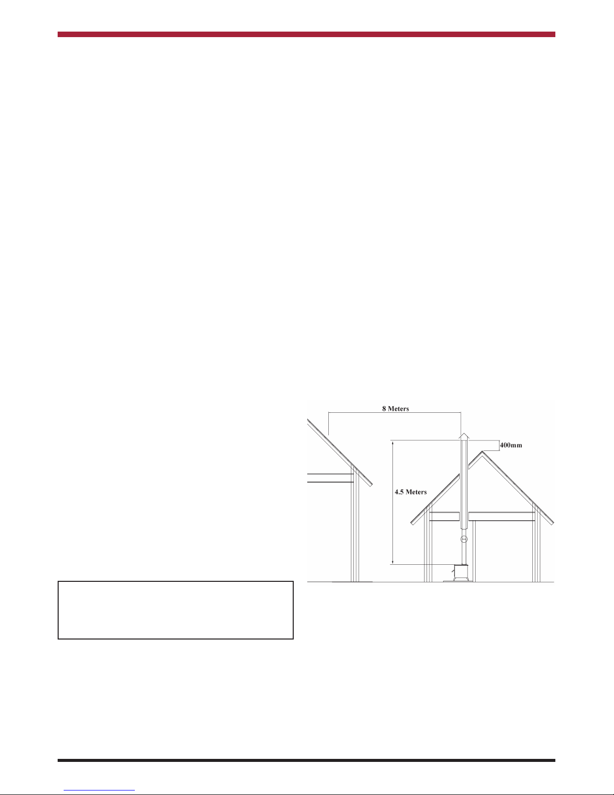
The flue termination point must be located to minimise any wind effects. Wind effects of suction,
pressure zones and turbulence can be created by
the roof and adjacent objects. Wind effects can also
be created by natural land contours.
To minimise the wind effects, the flue termination
point should be located a minimum of 400mm measured vertically from the roof or any other object that
may cause an obstruction and 8 meters measured
horizontally. Where this termination point does not
suffice it may be necessary to extend the flue pipe.
(See Fig.1)
Fig.1
Page 4
FLUE PIPES
A flue pipe should only be used to connect an appliance to a chimney and should not pass through any
roof space.
Flue pipes in cast iron, stainless steel or enamelled
steel are suitable for use on this appliance. All flue
pipes must meet the requirements of the relevant
standards.
Flue pipes with spigot and socket joints should be fitted with the socket uppermost.
Clearance to combustibles must be adhered to
when fitting the flue pipe.
3
Fig.4
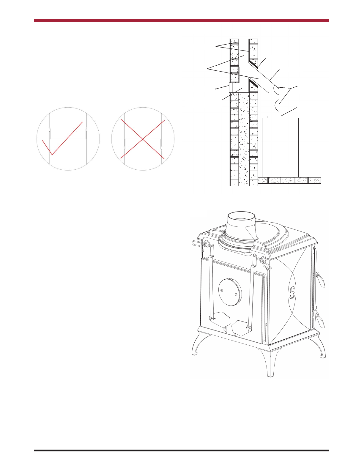
FLUE EXIT (TOP & REAR)
The stove is designed to allow the chimney be
cleaned through the stove. If bends in the chimney
make cleaning difficult, a means must be provided to
clean the chimney such as a soot box/access door
in the flue for cleaning. See Fig.3 for recommended
locations.
For top flue outlet see Fig.4, place the top flue connector on the flue outlet use fire cement to seal to
the heatexchanger, place fire cement into the groove
and then fit the top flue outlet spigot, clean away any
excess cement on the inside of the pipe. The back
flue outlet must be blanked off using the blanking
plate supplied.
Fig.3
Flue Liner
Sleeve
Flue Pipe
Possible
Positions
for access
Flue
Soot Door
Appliance Flue
Outlet
Appliance
Debris Collection
space
FLUE ORIENTATION ASSEMBLY
Fig.2
For back flue outlet fit the flue pipe direct to the back
flue outlet and seal using fire cement. Seal the top
flue outlet using the top flue blanking plate. Fit the
hob filler piece to the top flue blanking plate, see
Fig.5.
Page 5
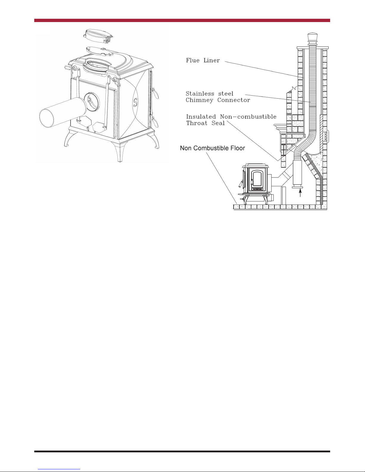
Fig.5
CHIMNEY
Do not connect to a chimney serving another
appliance.
The stove is a radiant room heater and must be connected to a chimney of the proper size and type.
The chimney must have a diameter of at least
150mm. It is best to connect to a chimney of the
same size, as connection to a larger size may result
in a somewhat less draught. If installation is into an
existing chimney then it must be sound and have no
cracks or other faults which might allow fumes into
the house. Where the chimney diameter is greater
than 200mm or the chimney is in need of repair the
chimney will need to be lined with a suitable
approved flue liner. Minimum chimney height 4.5
meters from stove flue outlet measured vertically.
The stove must be connected to a chimney with a
minimum continuous draft of 12 Pascals poor draft
conditions will result in poor performance.
In adverse weather conditions, down drafts may be
experienced causing smoke or fumes to spill into the
room. If this occurs shut the appliance down by
closing the air controls. If the problem persists seek
the advice of a chimney sweep.
When installing a chimney care must be taken to
ensure the chimney/flue does not become a fire hazard or a safety hazard where the flue pipe could be
touched. Follow the requirements from the relevant
building regulations.
4
Fig.6
Any existing chimney must be clear of obstruction
and have been swept clean immediately before
installation of the stove. If the stove is fitted in place
of an open fire then the chimney should be swept
one month after installation to clear any soot falls
which may have occurred due to the difference in
combustion between the stove and the open fire.
An approved single wall metal fluepipe is suitable for
connecting the stove to the chimney but is not suitable for use as the complete chimney.
The chimney and connecting flue must have a minimum diameter of 150mm and at no point must the
diameter reduce to less than the size of the outlet
socket of the stove.
Any bend in the chimney or connecting fluepipe
should not exceed 45
o
. 90obends should not be
used.
Soot Door
Page 6
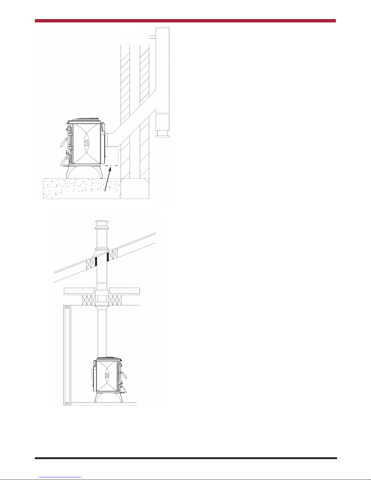
Fig.7
Fig.8
Combustible material should not be located where
the heat dissipating through the walls of fireplaces or
flues could ignite it. Therefore when installing the
stove in the presence of combustible materials due
account must be taken of the guidance on the separation of combustible material given in Building
Regulations.
5
Max. Horizontal Run
150mm
Page 7

Fig.9
Fig.10
Fig.11
Fig.12
Fig.13
Fig.14
6
CLEARANCE TO COMBUSTIBLES
CORNER INSTALLATION
ALCOVE INSTALLATION
FIREPLACE INSTALLATION
FLUE CLEARANCES
MINIMUM COMBUSTIBLE ALCOVE
MANTLE CLEARANCE
Page 8

If it is found that there is excessive draught in the
chimney then a draught stabiliser should be fitted.
Fitting of a draught stabiliser will affect the requirement for the permanent air supply into the room.
Adequate provision e.g. easily accessible soot door
or doors must be provided for sweeping the chimney
and connecting fluepipe.
ALL FLUE INSTALLATIONS ARE THE
RESPONSIBILITY OF THE CUSTOMER.
INSTALLATION CLEARANCES
Maintain at least the following clearances to all
combustible material:
VENTILATION & COMBUSTION AIR
REQUIREMENTS
It is imperative that there is sufficient air supply to
the stove in order to support correct combustion.
The air supply to this appliance must comply with
current Building Regulations. If another air using
appliance is fitted in an adjacent room it will be necessary to calculate an additional air supply.
All materials used in the manufacture of air vents
should be such that the vent is dimensionally stable,
corrosion resistant, and no provision for closure.
The effective free area of any vent should be ascertained before installation. The effect of any grills
should be allowed for when determining the effective
free area of any vent.
Air vents direct to the outside of the building should
be located so that any air current produced will not
pass through normally occupied areas of the room.
An air vent outside the building should not be located less than the dimensions specified within the
Building Regulations from any part of any flue terminal. These air vents must also be satisfactorily fire
proofed as per Building Regulations.
Air vents in internal walls should not communicate
with bedrooms, bedsits, toilets, bathrooms or rooms
containing a shower.
Air vents traversing cavity walls should include a
continuous duct across the cavity. The duct should
be installed in such a manner as not to impair the
weather resistance of the cavity.
Joints between air vents and outside walls should be
sealed to prevent the ingress of moisture. Existing
air vents should be of the correct size and unobstructed for the appliance in use. If there are fans or
other air using appliances installed in adjacent
rooms in the dwelling where the stove is installed,
additional air vents must be installed to deliver
adequate air supply to all air using appliances
operating at full output or max settings.
Where such an installation exists, a test for spillage
should be made with the fan or fans and other appliances using air in operation at full rate, (i.e.extraction fans, tumble dryers) with all external doors and
windows closed.
If spillage occurs following the above operation, an
additional air vent of sufficient size to prevent this
occurrence must be installed.
PERMANENT AIR VENT
The stove requires a permanent and adequate air
supply in order for it to operate safely and efficiently.
In accordance with current Building Regulations the
installer will have fitted a permanent air supply vent
into the room in which the stove is installed to provide combustion air. This air vent should not under
any circumstances be shut off or sealed.
Extractor Fan
There must not be an extractor fan fitted in the same
room as the stove as this can cause the stove to
emit smoke and fumes into the room.
7
From the Front 910mm
From the Back 750mm
From the Sides 750mm
From the Flue Pipe (Vertical no
heat shield fitted)
750mm
Mantle Clearance 700mm
Side Trim Clearance 750mm
Brick wall minimum clearance, but allow access
for controls, servicing & side load door.
Page 9

EXTERNAL DUCTED AIR
The primary air supply can be ducted from outside.
An aluminium flexible duct is available to order for
connection to the stove.
It is recommended to bring the air supply for the
stove into the house using a 4” non corrosive pipe.
Where the pipe meets the outside wall make sure a
vent cover is fitted properly to ensure no rodents can
enter via the vent pipe.
The vent pipe should be located to prevent the
ingress of moisture and in a location where it will not
get blocked with leaves or any other debris. As wind
effects can create suction and pressure zones of
opposite sides of the dwelling it is recommended to
run the air vent from opposite poles (North-South,
East-West) of the dwelling and tee off for the air supply to the stove. This should negate the effect
of suction and pressure zones. See Fig.15
Fig.15
Note: When Installing
outside air pipe adhere
to ‘Clearance to
Combustible’ Section.
CO ALARM
We recommend the fitting of a CO Alarm in the same
room as the appliance. Further guidance on the
installation of a carbon monoxide alarm is available
in EN 50292:2013 and from the alarm manufacturers instructions.
Provision of an alarm must not be considered a
substitute for either installing the appliance
correctly or ensuring regular servicing and
maintenance of the appliance and chimney
system.
WARNING:-
If the CO Alarm sounds unexpectedly:-
1. Open Doors and windows to ventilate the
room and then leave the premises.
2. Let the fire go out.
8
Aluminium Flexible
Duct
Connector Saddle
Page 10

LOCATION
There are several conditions to be considered in
selecting a location for your Reginald Stove.
a. Position in the area to be heated, central
locations are usually best.
b. Allowances for proper clearances to
combustibles.
FLOOR PROTECTION
It is recommended that this appliance is installed on
a solid, level, non combustible hearth conforming to
current Building Regulations.
It is recommended that a minimum clearance of
150mm be maintained from the left hand side,
460mm from right hand side and 250mm from rear
of the appliance to a tiled fireplace or masonry wall,
as access is required for the controls and side load
door. See Fig.16.
FLUE LOCATIONS
Flue outlet to suit 150mm internal diameter flue pipe.
Fig.17
9
Fig.16
HANDOVER
On completion of the installation allow a suitable
period of time for any fire cement and mortar to dry
out, when a small fire may be lit and checked to
ensure the smoke and fumes are taken from the
stove up the chimney and emitted safely to the
atmosphere. Do not run at full output for at least 24
hours.
Ensure that the operating instructions for the stove
are left with the customer. Ensure to advise the customer on the correct use of the appliance with the
fuels likely to be used on the stove and warn them to
use only the recommended fuels for the stove.
Advise the user what to do should smoke or fumes
be emitted from the stove.
Page 11

TECHNICAL DATA
WOOD
Nominal Output: (kW)
Room
10 kW
Typical refuelling intervals to obtain nominal
outputs:
.75 hrs
Flue Gas Mass Flow: 8.9 g/s
Flue Gas Temperature at Nominal Output: 318oC
Gross Weight: 250kgs
Flue Outlet: 150mm
Flue Draught: 12 Pascals
Max. Log Size: 480mm
WARNING: DO NOT OBSTRUCT PRIMARY AIR SUPPLY TO THE STOVE
SPECIFICATION
Note: Dimensions stated are in millimetres unless otherwise stated and may be subject to a slight +/- variation.
10
Fig18
Page 12

INSTALLATION CHECK LIST
Flue System
1. Minimum Flue Height of 4.5 metres.
2. Appliance should be connected to a minimum of 1.8 metres of 150mm.
flue pipe with a horizontal run not exceeding 150mm.
3. Appliance should be connected to a chimney of less than 200mm in diameter
(otherwise the chimney must be lined with a 150mm flue liner).
4. The chimney venting position must be above the apex of the roof or adjacent
outside obstructions.
5. The chimney serving this appliance should not serve any other appliance.
6. Access should be provided to the chimney serving the appliance to allow for cleaning.
Location
7. Clearance to combustible materials must be adhered to as described in the Clearance
to Combustible section.
8. The stove must be installed on a floor protector that covers the area under the stove
and extends 18” to the front & 6” to the sides and back.
Ventilation & Combustion Air Requirements
9. The room in which the appliance is located should have an air vent of adequate
size to support correct combustion (see Ventilation & Combustion Air Requirement
Section for specific details).
Tick
11
Page 13

12
THE REGINALD WOOD BURNER NON BOILER STOVE
OPERATING INSTRUCTIONS
When operating and maintaining your Stove respect
basic standards of fire safety. Read these instructions carefully. All relevant European and National
Standards must be complied with when installing
this appliance. Failure to do so may result in damage to persons and property. Consult your local
Municipal office and your insurance representative
to determine what regulations are in force. Save
these instructions for future reference.
The appliance is suitable for intermittent operation
on wood logs up to a length of 420mm.
All fuels should be stored under cover and kept as
dry as possible prior to use.
Use recommended fuels only, this product is not to
be used as an incinerator or to burn coal or liquid
fuels . The stove must be operated with the doors
closed at all times except for refuelling.
WARNING: This appliance is hot while in operation and retains its heat for a long period of time
after use. Children, aged or infirm persons
should be supervised at all times and should not
be allowed to touch the hot working surfaces
while in use or until the appliance has thoroughly cooled.
IMPORTANT NOTES
1. Do not burn fuel with a high moisture content,
such as unseasoned timber. This will result in a
build up of tar in the stove and in the chimney.
2. Clean the flue-ways of the stove weekly and
ensure that there are no blockages. Check flueways before lighting especially after a prolonged
shut down period. See baffle removal.
3. Never allow a build up of ashes in the ash pan,
as this will cause the grate to burn out prematurely.
4. Allow adequate air ventilation to ensure plenty
of air for combustion.
5. The chimney should be cleaned at least twice a
year by a competent engineer.
6. Regular cleaning of the glass will prevent permanent staining. Clean with soapy water when
cool.
7. Keep all combustible materials a safe distance
away from unit, please see section for clearances to combustibles.
8. Do not use an aerosol spray on or near the
stove when it is alight.
9. This appliance is not suitable for use in a shared
flue system.
10. Do not operate the stove with either the fire door
or ash door open.
SIDE LOAD DOOR
A side load door is provided for easier loading of
logs, the side load door is operated using a detachable handle, the detachable handle should be
removed when the stove is in use. Adequate clearance will need to be provided for opening and
fuelling through the side load door.
Fig 19
Page 14

LIGHTING
1. Open both the primary and secondary air controls.
2. Cover with crumpled pieces of paper.
3. Lay 10-12 pieces of kindling on top of the paper towards the back of the firebox.
4. Ignite and close the firedoor.
5. Under no circumstances should any flammable liquid i.e. petrol, paraffin etc., be
used to light the fire.
6. When the kindling is well alight open the firedoor and add more kindling of a larger size
to sustain the fire. Close the firedoor.
7. When a hot fuel bed is established add the normal fuel.
8. When well lighted, adjust the air controls to give the required heat output.
9. To shut the fire down, do not add fuel, make sure that the firedoor is properly closed and
that the primary and secondary air controls are all in the closed position. Cutting off the
air supply will reduce the heat output.
10. Following a prolonged shutdown of the appliance perhaps after the summer break,
ensure the flueway is free from obstruction prior to re-lighting.
Re-fuelling-Open the firedoor and reload, close the firedoor.
Fig.20
Before lighting the stove check with the installer that the installation work and
commissioning checks described in the installation instructions have been carried
out correctly and that the chimney has been swept clean, is sound and free from any
obstructions. As part of the stove’s commissioning and handover the installer
should have demonstrated how to operate correctly.
13
Page 15

or beyond as is required to control the heat output,
the secondary air inlet can remain open at all times
except when a very low output fire is required where
the primary should be fully closed and the secondary can be reduced to control the heat output.
Controls may become hot when the stove is in operation please use the glove provided.
RECOMMENDED FUELS
All fuels should be stored under cover and kept
as dry as possible prior to use.
This appliance has been tested using seasoned
wood logs. Other fuels are commercially available
and may give similar results. Wood logs up to
480mm long are suitable. All fuels should be stored
under cover and kept as dry as possible prior to use.
Do not use fuels with a Petro-coke ingredient as this
may cause the grate to overheat, causing damage.
Reduced outputs will result when fuels of lower
calorific values are used. Never use gasoline or
gasoline type lantern fuel, kerosene, charcoal lighter
fluid or similar liquids to start or freshen up a fire in
this heater. Keep all such liquid well away from the
heater at all times. Operate the stove only with the
fuelling door closed except for re-fuelling.
WARNING:
Properly installed, vented, operated and maintained this stove will not emit fumes into the
dwelling. Occasional fumes from de-ashing and
re-fuelling may occur. However, persistent fume
emission is potentially dangerous and must not be
tolerated. If fume emission does persist, then the
following immediate action should be taken -
(a) Open doors and windows to ventilate room and
then leave the premises.
(b) Let the fire out.
(c) Check for flue or chimney blockage and clean
if required.
(d) Do not attempt to relight the fire until the cause
of the fume emission has been identified and
corrected. If necessary seek expert advice.
The most common cause of fume emission is flueway or chimney blockage. For your own safety
these must be kept clean at all times.
14
Fig.22
Fig.21
AIR CONTROLS
This product has two independent air controls for
primary and secondary. Secondary control is located
on the left and the primary on the right.
Raise the lever to increase the air supply and lower
it reduce it.
At ignition open both primary and secondary air controls to the maximum, once the fire has established
the primary air control should be closed to halfway
REFUELLING
To achieve the nominal output the product would
need to be refuelled at 45 minute intervals with a fuel
load of approximately 2.75kg. Do not overfill the
combustion chamber, ensure that all logs are
retained in the fire using by the fire fence. Reduced
outputs will result when fuels of lower calorific values
are used. Following refuelling open the ash door
slightly until a flame is established for best combustion of the wood.
Secondary Air Control
Primary Air Control
Open
Open
Closed
Closed
Page 16

DE-ASHING & DISPOSAL
De-Ashing must be carried out when the stove is
cold. Brush the ashes through the grate into the
ashpan below.
The ashpan should be emptied every day. If ashes
are allowed to build to grate level you could damage
the firebars by overheating.
Ashes should be placed in a metal or other noncombustible container with a tight fitting lid. The
closed container of ashes should be placed on a
non-combustible material, pending final disposal. If
ashes are buried in soil, or otherwise dumped they
should be retained in the closed container until they
are thoroughly cooled. See Fig.23.
Fig.23
CHIMNEY CLEANING/ BAFFLE REMOVAL
Remove the hanging shields by lifting and pulling
them towards the front of the stove and sliding
towards the centre of the stove. Remove the protection plate on the left hand side of the stove. Then
remove the back casting by sliding it forward and to
the left, remove the secondary air pipes by twisting
the pipe clear of the hook push the pipe to the right,
the left end will fall into the stove and the pipe can
be removed. Remove the top baffle by sliding it to
the fornt of the stove, lift it and push it to one side
allowing the opposite to fall into the stove.
Replace in reverse order when chimney cleaning is
complete. See Figs 24 & 25.
NOTE: Where the chimney is believed to have
served an open fire installation it is possible that the
higher flue gas temperature from a closed appliance
may loosen deposits that were previously firmly
adhered, with the consequent risk of flue blockage,
it is therefore recommended that the chimney be
swept a second time within a month of regular use
after installation.
15
Fig.25
Fig.24
FIRE SAFETY
To provide reasonable fire safety, the following
should be given serious consideration.
1. Do not over fire the stove.
2. Over-firing will also damage painted or enamel
finish.
3. Install a smoke detector in the room.
4. A conveniently located class A fire extinguisher to
contend with small fires resulting from burning
embers.
5. A practical evacuation plan.
6. A plan to deal with a chimney fire as follows:(a) Notify the fire department.
(b) Prepare occupants for immediate evacua-
tion.
(c) Close all openings into the stove.
(d) While awaiting the fire department watch for
ignition to adjacent combustibles from over-
heated flue pipe or from embers or sparks
from the chimney.
Ashpan
Ashpan Lid
Lifting Tool
Page 17

VENTILATION
This appliance requires air for combustion which
must be either ducted from outside or provided
through ventilation openings, ventilation and air inlet
grilles must be kept free from blockage. Where more
than one air using appliance is installed in the
dwelling adequate provision must be made for
when both appliances are in use.
CO ALARM
Your installer should have fitted a CO alarm in the
same room as the appliance.
If the CO Alarm sounds unexpectedly:-
1. Open Doors and windows to ventilate the
room and then leave the premises.
2. Let the fire go out.
GLASS CLEANING
The glass will self clean when there is sufficient heat
generated by the burning fuel. If a build-up of creosote occurs on the glass it may be due to draft conditions, poor quality fuel or very low burning for a
long time. It is best to clean the glass when it is
thoroughly cooled.
SUMMER SHUTDOWN
For summer shutdown of the stove, ensure all ashes
have been cleaned from the ash compartment and
that the air control is open, to avoid condensation in
the stove firebox and possible corrosion during this
shutdown period.
DOOR LATCH ADJUSTMENT
If the door latch should be come loose over time due
to compression/ hardening of the rope inside the fire
door, and side load door, an adjustment can be carried out by moving one of the washers to the other
side of the latch.
Remove a washer from between the latch and the
door and replace it between the latch and the nut,
see Figs. 26 & 27 for example.
VITREOUS ENAMEL CLEANING
General cleaning must be carried out when the
stove is cool.
If this stove is finished in a high gloss vitreous
enamel, to keep the enamel in the best condition
observe the following tips:
1. Wipe over daily with a soapy damp cloth,
followed by a polish with a clean dry duster.
2. For stubborn deposits a soap impregnated
pad can be carefully used on the vitreous
enamel.
3. Use only products recommended by the
Vitreous Enamel Association, these products
carry the Vitramel label.
4. DO NOT USE ABRASIVE PADS OR OVEN
CLEANSERS CONTAINING CITRIC ACID
ON ENAMELLED SURFACES. ENSURE
THAT THE CLEANSER MANUFACTUR
ERS INSTRUCTIONS ARE ADHERED TO.
Fig 26
Fig 27
16
Page 18

17
EXPLODED VIEW
Page 19

18
1. OPERATING TOOL - B00009DZZ
2. TOP FLUE OUTLET
- B00053AZZ
3. FLUE BLANKING PLATE - B00064AZZ
4. STOVE LEG - B000595AZZ
5. HOB - B00599AZZ
6. HOB FILLER PIECE - B00601AZZ
7. FIRE DOOR - B00602AZZ
8. ASH DOOR - B00603AZZ
9. BASE - B00634AZZ
10. FRONT - B00635AZZ
11. RIGHT HAND SIDE - B00636AZZ
12. LEFT HAND SIDE - B00637AZZ
13. BACK PANEL - B00638AZZ
14. SIDE DOOR - B00639AZZ
15. SIDE DOOR LINER - B00640AZZ
16. TOP FLUE BLANKING PLATE - B00641AZZ
17. TOP FLUE CONNECTION - B00642AZZ
18. DOOR GLASS CLIP - F00003AXX
19. ASHPAN - F01023AXX
20. DAMPER PLATE - F01169AXX
21. AIR CHANNEL RH - F01188AXX
22. AIR CHANNEL LH - F01189AXX
23. SECONDARY AIR TUBE (REAR) - F01190AXX
24. AIR BOX COVER - F01191AXX
25. LINK ARM - F01192AXX
26. SECONDARY AIR TUBE (FRONT) - F01193AXX
27. SERIAL NUMBER PLATE - N00234BXX
28. DATA PLAQUE - N00619AXX
29. HEAT EXCHANGER - Q00781AXX
30. GRATE - Q00782AXX
31. BACK LINER - Q00783AXX
32. SIDE LINER LH - Q00784AXX
33. SIDE LINER RH - Q00785AXX
34. FLUE CLEANING DOOR - Q00786AXX
35. AIR WASH CASTING - Q00787AXX
36. SHIELD - Q00788AXX
37. GLASS - T00100AXX
38. HINGE - U00153AXX
39. HANDLE - U00164AXX
40. DOOR HANDLE - U00191AXX
41. HINGE - U00193AXX
42. OPERATING HANDLE - U00195AXX
43. DOOR LATCH - V00023AXX
44. SPACER TO DOOR HANDLE - V00035AXX
45. AXLE - V00827AXX
46. FRONT STRIP - V00932AXX
47. HINGE PIN (CAM ACTION) - V00984AXX
48. BADGE - V01025AXX
52. FIRE FENCE - Z00042AXX
SPARE PARTS
For supply of spare parts please contact you local
distributor. Use only spare parts recommended by
the manufacturer. Any modification to the appliance
other than that recommended by the manufacturer is
not permitted and will void the warranty.
PARTS LIST
Page 20

Manufactured by
Waterford Stanley Ltd.,
Unit 210, IDA Industrial Estate, Cork Road,
Waterford, Ireland.
Tel: (051) 302300 Fax (051) 302315
DP 141223
N00562AXX
 Loading...