

Falcon 4M30, 4M60, PT-41-04M60-XX-R, PT-22-04M30-XX-R, PT-42-04M60-XX-R User Manual
...
4 Megapixel 30/60 fps Area Scan Cameras
3-Jun-11
03-032-20044-03
www.teledynedalsa.com
4M30 and 4M60
Falcon
Monochrome and Color Camera Manual
PT-41-04M60-XX-R
PT-42-04M60-XX-R
PT-21-04M30-XX-R
PT-22-04M30-XX-R

Falcon 4M Camera Manual
2
North America
605 McMurray Rd
Waterloo, ON N2V 2E9
Canada
Tel: 519 886 6000
Fax: 519 886 8023
www.teledynedalsa.com
sales.americas@teledynedalsa.com
support@teledynedalsa.com
Europe
Breslauer Str. 34
D-82194 Gröbenzell (Munich)
Germany
Tel: +49 - 8142 – 46770
Fax: +49 - 8142 – 467746
www.teledynedalsa.com
sales.europe@teledynedalsa.com
support@teledynedalsa.com
Asia Pacific
Ikebukuro East 13F
3-4-3 Higashi-Ikebukuro
Toshima-ku, Tokyo 170-0013
Japan
Tel: 81 3 5960 6353
Fax: 81 3 5960 6354 (fax)
www.teledynedalsa.com
sales.asia@teledynedalsa.com
support@teledynedalsa.com
© 2011 Teledyne DALSA. All information provided in this manual is believed to be
accurate and reliable. No responsibility is assumed by Teledyne DALSA for its use.
Teledyne DALSA reserves the right to make changes to this information without notice.
Reproduction of this manual in whole or in part, by any means, is prohibited without
prior permission having been obtained from Teledyne DALSA.
About Teledyne Technologies and Teledyne DALSA, Inc.
Teledyne Technologies is a leading provider of sophisticated electronic subsystems,
instrumentation and communication products, engineered systems, aerospace engines,
an d en erg y and p ow er gener ation system s. Teled yne Techn olog ies‘ op erations are
primarily located in the United States, the United Kingdom and Mexico. For more
infor m ation , visit Teled yn e Tech n olog ies‘ we bsite at www.teledyne.com.
Teledyne DALSA, a Teledyne Technologies company, is an international leader in high
performance digital imaging and semiconductors with approximately 1,000 employees
worldwide, headquartered in Waterloo, Ontario, Canada. Established in 1980, the
company designs, develops, manufactures and markets digital imaging products and
solutions, in addition to providing MEMS products and services. For more information,
visit Teled y n e DALSA‘s w ebsite at w ww .teled yn ed alsa.com.
Support
For further information not included in this manual, or for information on Teledyne
DALSA‘s extensive line of im age sen sing prod ucts, p lease contact:
Camera Link is a trademark registered by the Automated Imaging Association, as chair of a committee of
industry members includ ing Teledyne DALSA.
03-032-20044-03 Teledyne DALSA

Falcon 4M Camera Manual
3
Contents
Introduction to the 4 Megapixel Falcon Cameras _________________________________ 5
1.1 Camera Highlights ....................................................................................................................................................... 5
1.2 Camera Performance Specifications ............................................................................................................................. 6
1.3 Cosmetic Specifications ................................................................................................................................................ 9
1.4 Image Sensor and Pixel Readout................................................................................................................................. 11
1.5 Responsivity ................................................................................................................................................................. 13
1.6 Shock and Vibration..................................................................................................................................................... 15
1.6 Shock and Vibration..................................................................................................................................................... 15
Camera Hardware Interface ________________________________________________ 17
2.1 Installation Overview ................................................................................................................................................... 17
2.2 Input/Output Connectors and LED ............................................................................................................................... 18
2.2.1 LED Status Indicator ............................................................................................................................... 18
2.2.2 Camera Link ........................................................................................................................................... 19
2.2.3 Power Connector .................................................................................................................................... 21
Software Interface: How to Control the Camera __________________________________ 23
3.1 First Power Up Camera Settings .................................................................................................................................. 26
3.2 Saving and Restoring Settings ..................................................................................................................................... 27
3.3 Camera Output Format ................................................................................................................................................ 27
3.3.1 How to Configure Camera Output .......................................................................................................... 27
3.3.2 Setting the Camera Link Mode............................................................................................................... 29
3.3.3 Setting the Camera Link Strobe Frequency ............................................................................................ 30
3.4 Setting Exposure Mode, Frame Rate and Exposure Time ............................................................................................ 30
3.4.1 Non-concurrent vs. concurrent modes of operation ................................................................................ 30
3.4.2 Setting the Exposure Mode..................................................................................................................... 32
3.4.2 Setting the Frame Rate .......................................................................................................................... 35
3.4.3 Setting the Exposure Time ..................................................................................................................... 36
3.4.4 Enabling EXSYNC Debounce Circuit ....................................................................................................... 37
3.5 Snapshot Modes ........................................................................................................................................................... 37
3.6 Setting a Vertical Window of Interest ........................................................................................................................... 42
3.7 Flat Field Correction .................................................................................................................................................... 46
3.7.1 Selecting Factory or User Coefficients .................................................................................................... 50
3.7.2 Enabling Pixel Coefficients ..................................................................................................................... 51
Teledyne DALSA 03-032-20044-03

Falcon 4M Camera Manual
4
3.7.3 Selecting the Calibration Sample Size ................................................................................................... 51
3.7.4 Performing FPN Calibration .................................................................................................................. 52
3.7.5 Performing PRNU Calibration ............................................................................................................... 53
3.7.6 Saving, Loading and Resetting Coefficients ........................................................................................... 55
3.7.7 Returning Pixel Coefficient Information ................................................................................................ 56
3.8 Offset and Gain Adjustments ....................................................................................................................................... 57
3.9 Generating a Test Pattern............................................................................................................................................ 61
Optical and Mechanical Considerations ________________________________________ 65
4.1 Mechanical Interface .................................................................................................................................................... 65
4.2 Lens Mounts ................................................................................................................................................................. 66
4.3 Optical Interface ........................................................................................................................................................... 66
Troubleshooting ________________________________________________________ 69
5.1 Common Solutions ....................................................................................................................................................... 69
5.2 Troubleshooting Using the Serial Interface ................................................................................................................. 70
5.3 Specific Solutions ......................................................................................................................................................... 70
5.4 Product Support ........................................................................................................................................................... 72
Camera Link™ Reference, Timing, and Configuration Table _________________________ 73
Error Handling and Command List ___________________________________________ 79
B1 All Available Commands .............................................................................................................................................. 79
EMC Declaration of Conformity _____________________________________________ 85
Revision History ________________________________________________________ 87
Index _______________________________________________________________ 89
03-032-20044-03 Teledyne DALSA

Falcon 4M Camera Manual
5
Introduction to the 4
Megapixel Falcon
Cameras
1
1.1 Camera Highlights
Features
4 mega pixels, 2352 (H) x 1728 (V) resolution, CMOS area camera
Global shutter (non-rolling) for crisp images
60 fps model or 30 fps model
Color and monochrome models
Vertical windowing for faster frame rate
7.4 µm x 7.4 µm pixel pitch
4 x 80 MHz or 2 x 80 MHz data rates
Nominal broadband responsivity of 18.4 DN/ (nJ/ cm2)
Good NIR response
8 or 10 bit selectable output
Dynamic range of 57 dB
Base or Med ium Camer a Lin k™ interface
RoHS and CE compliant
Programmability
A simple ASCII protocol controls gain, offset, frame rates, trigger mode, test pattern
output, and camera diagnostics.
The serial interface (ASCII, 9600 baud, adjustable to 19200, 57600, 115200) operates
through Camera Link.
Teledyne DALSA 03-032-20044-03

Falcon 4M Camera Manual
6
Model Number
Description
PT-21-04M30-XX-R
4M resolution, 2 sensor taps, 30 frames per second, RoHS
compliant, monochrome.
PT-41-04M60-XX-R
4M resolution, 4 sensor taps, 60 frames per second, RoHS
compliant, monochrome.
PT-22-04M30-XX-R
4M resolution, 2 sensor taps, 30 frames per second, RoHS
compliant, color.
PT-42-04M60-XX-R
4M resolution, 4 sensor taps, 60 frames per second, RoHS
compliant, color.
Feature / Specification
Notes
Resolution
2352 (H) x 1728 (V) pixels
Pixel Fill Factor
45 %
Effective fill factor
with micro-lenses
60 %
# of Lines per Frame
1728 lines
Output Format (# of taps)
2 (4M30) or 4 (4M60)
Description
The 4 mega pixel Falcon cameras are our most advanced high-speed area array cameras.
With data rates up to 320 MHz, these cameras are capable of capturing crisp images at
incredibly fast speeds. Programmable features and diagnostics are accessible through the
Camera Link ™ MDR26 con n ector. Color and monochrome options make the Falcon 4M
camera a very versatile choice.
Applications
The 4M Falcon cameras are ideal for applications requiring high speed, superior image
quality, and high responsivity. Applications include:
PCB inspection
3D solder paste inspection
2D and 3D wafer bump inspection
Semiconductor wafer inspection
Flat panel display inspection
Solar panel inspection
Industrial metrology
Traffic management
General machine vision
Models
The Falcon 4M camera is available in the following models:
Falcon 4M Camera Models Overview
1.2 Camera Performance Specifications
Camera Performance Specifications
03-032-20044-03 Teledyne DALSA

Falcon 4M Camera Manual
7
Bayer Filter (color only)
See Fig. 2 for RGB filter location
Optical Interface
Notes
Back Focal Distance
Sensor die to mounting
plate
6.56 mm
5
Sensor Alignment
x
y
z
z
±0.10 mm
±0.10 mm
±0.25 mm
±0.3°
Lens Mount
F-mount adapter available
Lens Mount Hole
M42 x 1
Mechanical Interface
Notes
Camera Size
94 x 94 x 48 mm
Mass
<550 g
Connectors
pow er connector
data connector
6 pin male Hirose
2 x MDR26 female
Electrical Interface
Notes
Input Voltage
+12 to +15 Volts
6
Power Dissipation
10 typ, 14 Watts max
Operating Temperature
0 to 50 °C
1
Data Output Format
8 or 10 user selectable bits
Output Data Configuration
Base or Medium Camera Link
Operating Ranges
Notes
Minimum Frame Rate
1 Hz
Maximum Frame Rate
60.4 Hz (4M60)
30.6 Hz (4M30)
4
Data Rate
80 MHz
Dynamic Range
(10 bits @ nominal gain)
682 : 1 typ.
2
Random Noise
1.5 typ, 2.0 max DN rms
Broadband Responsivity (mono)
18.4 typ DN/ (nJ/ cm2)
7
Responsivity
See Figs. 5, 7, and 8
Quantum Efficiency
See Figs. 6
DC Offset
0 DN
7
Antiblooming
>1000x saturation
FPN
0.5 typ, 1.0 max DN rms
PRNU
1.5 typ, 2.6 max DN rms
8
Integral non-linearity
<2% DN
3
Teledyne DALSA 03-032-20044-03

Falcon 4M Camera Manual
8
Operating Ranges
Notes
Saturation Equivalent Exposure
55 typ nJ/ cm2
Noise Equivalent Exposure
80 typ pJ/ cm2
Saturation Output Amplitude
1023 DN
Test conditions unless otherwise noted:
sem 2 (exposure mode 2).
ssf 55 (55 frames per second rate).
set 2000 (2 millisecond exposure time).
sem 2 (Exposure mode 2) .
Full frame/ window.
clm 16 (4 tap, 10 bit).
sot 320 (80 MHz camera link strobe).
efd 1 (Snapshot mode 1).
snd 1 (Number of fast frame dumps = 1).
Light Source: Broadband Quartz Halogen, 3250K (3050 to 3450), with a 750 nm cutoff
filter .
Ambient test temperature 25°C.
Average output 840 DN .
Flat field correction (FFC) turned on.
Notes:
1. Measured at the front plate.
2. Based on output at 1023 DN.
3. Output over 10-90%.
4. Snapshot mode 0 allows for marginally higher frame rates.
5. Optical distance.
6. +12V consumes the least amount of power.
7. With FFC on. Responsivity is not calibrated when FCC is turned off.
8. Measured at half saturation.
03-032-20044-03 Teledyne DALSA

Falcon 4M Camera Manual
9
Cosmetic Specification
Maximum Number of Defects
Hot pixel defects
1
Single pixel defects
100
Clusters defects
No limit (refer to the Note below)
Spot d efects
1
Column defects
0
Row defects
0
1.3 Cosmetic Specifications
Please note, for this section only, the following values are considered preliminary
information and subject to change without notice.
Monochrome Sensor Cosmetic Specifications
The following table highlights the current cosmetic specifications for the sensor used
inside the Falcon 4M60 and 4M30 cameras. The sensor has 4 megapixels (2352 x 1728),
global shuttering and is capable of 60 fps.
Sensor Cosmetic Specifications
Definition of cosmetic specifications
Hot pixel defect
Pixel whose signal, in dark, deviates by more than 400 DN (10 bits) from the average of all
the pixels.
Single pixel defect
Pixel whose signal, at nominal light (illumination at 50% of saturation), deviates by more
than ±30% from its neighboring pixels.
Cluster defect
A grouping of at most 8 pixel defects within an area of 3 x 3 pixels.
Spot defect
A grouping of 9 pixel defects within an area of 3 x 3 pixels.
Column defect
A column which has 12 pixel defects in a 1*12 kernel.
Row defect
A horizontal grouping of more than 4 pixel defects between at least 2 good pixels on both
sides, where single good pixels between 2 defective pixels are considered defective.
Test conditions
Digital gain – 1X.
Nominal light = illumination at 50 % of saturation.
Frame Rate = 60 fps (Falcon 4M60), 30 fps (Falcon 4M30)
Teledyne DALSA 03-032-20044-03

Falcon 4M Camera Manual
10
Cosmetic Spec
Max. Deviation
from Mean
Cluster Size
Max Number of Defects
Glass defects
5 % 9 0
Cosmetic Specification
Maximum Number of Defects
Dark pixel defects (> 300 DN)
50
Dark pixel defects (> 600 DN)
1
Single pixel defects
100
Integration time = 15 ms
Ambient Temperature of 25 °C
Note: While the number of clusters is not limited by a maximum number, the total
number of defective pixels cannot exceed 100. Therefore, you could have 12 clusters of 8
in size (12 x 8 = 96), but you could not have 13 clusters of 8 in size (13 x 8 = 104).
The probability of 12 clusters of 8 is negligible and is only used as an example.
Camera Cosmetic Specification
Beyond sensor cosmetic testing, the camera is placed under additional testing to more
closely examine potential cosmetic defects due to the sensor glass.
Camera Cosmetic Specifications - Glass
Definition of blemishes
Glass defects
A group of pixels exceeding the given cluster size and the maximum deviation from the
mean. Images are taken at nominal light (illumination at 50 % of the linear range). A
cluster is defined as a grouping of pixels. A grouping of pixels refers to adjacent pixels or
pixels that touch.
In addition, the camera is examined against the following cosmetic specifications.
Camera Cosmetic Specifications – Sensor & Glass
Definition of cosmetic specifications
Dark pixel defects
Pixel whose signal, in dark, exceeds the given threshold (10 bits).
Single pixel defect
Pixel whose signal, at nominal light (illumination at 50 % of saturation), deviates by more
than ± 30 % from its neighboring pixels.
Test conditions
Digital gain – 1X.
Nominal light = illumination at 50 % of saturation.
03-032-20044-03 Teledyne DALSA

Falcon 4M Camera Manual
11
Ro w 2
0
Tap 2
Co lum n 235
Ro w 2
49
Tap 1
Co lum n 23
Ro w 1
Co lum n 1
Tap 1
Ro w 1
Co lum n 2
Tap 2
Ro w 1
Co lum n 3
Tap 3
Ro w 1
Co lum n 235 1
Tap 3
Ro w 1
Co lum n 235 0
Tap 2
Ro w 1
Co lum n 234 9
Tap 1
Ro w 2
Co lum n 1
Tap 1
Ro w 2
Co lum n 2
Tap 2
Ro w 2
Co lum n 3
Tap 3
Ro w 2
1
Tap 3
Co lum n 235
Ro w 1 727
Co lum n 235 1
Tap 3
Ro w 1 727
Co lum n 235 0
Tap 2
Ro w 1 727
Co lum n 234 9
Tap 1
Ro w 1 727
Co lum n 3
Tap 3
Ro w 1 727
Co lum n 2
Tap 2
Ro w 1 727
Co lum n 1
Tap 1
Ro w 1 727
Co lum n 235 2
Tap 4
Ro w 2
Tap 4
Co lum n 235 2
Ro w 1
Co lum n 235 2
Tap 4
Ro w 1 728
Co lum n 1
Tap 1
Ro w 1 728
Co lum n 2
Tap 2
Ro w 1 728
Co lum n 3
Tap 3
Ro w 1 728
Co lum n 234 9
Tap 1
Ro w 1 728
Co lum n 235 0
Tap 2
Ro w 1 728
Co lum n 235 1
Tap 3
Ro w 1 728
Co lum n 235 2
Tap 4
Pixel
1
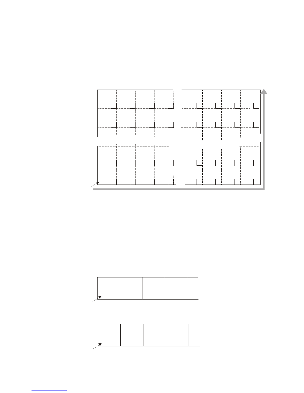
Pixel read out direction is left to right then bottom to top
Ro w 1
Co lum n 4
Tap 4
Ro w 2
Co lum n 4
Tap 4
Ro w 1 727
Co lum n 4
Tap 4
Ro w 1 728
Co lum n 4
Tap 4
Frame Rate = 60 fps (Falcon 4M60), 30 fps (Falcon 4M30).
Integration time = 15 ms.
Ambient Temperature of 25 °C.
Note: all of the above sensor and camera cosmetic specifications are w ith flat field
correction turned off (epc 0 0). There are no post flat field correction (epc 1 1) camera
cosmetic specifications.
Color Cosmetic specifications
Color camera cosmetic specifications in the dark (such as hot pixels) will be the same as
monochrome specifications. Specifications in the light are pending.
1.4 Image Sensor and Pixel Readout
The camera uses our new DCR2417M, 4 mega pixel, 2352 x 1728 CMOS sensor.
Figure 1: 4 Tap Sensor Block Diagram
Note: As viewed from the front of the camera without lens. The bottom of the camera has
a ¼-20 tripod mount.
Teledyne DALSA 03-032-20044-03
Falcon 4M Camera Manual
12
Row 2
0
Tap 2
Column 235
Row 2
49
Tap 1
Column 23
Row 1
Column 1
Tap 1
Row 1
Column 2
Tap 2
Row 1
Column 3
Tap 3
Row 1
Column 2351
Tap 3
Row 1
Column 2350
Tap 2
Row 1
Column 2349
Tap 1
Row 2
Column 1
Tap 1
Row 2
Column 2
Tap 2
Row 2
Column 3
Tap 3
Row 2
1
Tap 3
Column 235
Row 1727
Column 2351
Tap 3
Row 1727
Column 2350
Tap 2
Row 1727
Column 2349
Tap 1
Row 1727
Column 3
Tap 3
Row 1727
Column 2
Tap 2
Row 1727
Column 1
Tap 1
Row 1727
Column 2352
Tap 4
Row 2
Tap 4
Column 2352
Row 1
Column 2352
Tap 4
Row 1728
Column 1
Tap 1
Row 1728
Column 2
Tap 2
Row 1728
Column 3
Tap 3
Row 1728
Column 2349
Tap 1
Row 1728
Column 2350
Tap 2
Row 1728
Column 2351
Tap 3
Row 1728
Column 2352
Tap 4
Pixel
1
Pixel read out direction is left to right then bottom to top
Row 1
Column 4
Tap 4
Row 2
Column 4
Tap 4
Row 1727
Column 4
Tap 4
Row 1728
Column 4
Tap 4
R
B
GB
R
B
GR
R
B
R
B
GRGR
GR GR
B B
R R
GR GR
B B
R R
GR
GB GB GB
GB GB GB
GB
GB: Green-Blue
B: Blue
R: Red
GR: Green-Red
Ro w 1
Co lum n 1
Tap 1
Ro w 1
Co lum n 2
Tap 2
Ro w 1
Co lum n 3
Tap 3
Pixel
1
Ro w 1
Co lum n 4
Tap 4
Row 1
Column 1
Tap 1
Row 1
Column 2
Tap 2
Row 1
Column 3
Tap 1
Pixel
1
Row 1
Column 4
Tap 2
The color camera model has a Bayer filter applied to the CMOS sensor to allow for color
separation. Each individual pixel is covered by either a red, green, or blue filter as shown
in the figure below. The camera outputs raw color data--no color interpolation is
performed. Full RGB images can be obtained by performing color interpolation on the
frame grabber or host PC.
Figure 2: Color Sensor Block Diagram
Camera Readout and Coordinates
The camera readout begins with pixel 1 and reads out successive pixels from left to right
until the entire row is completed. This process is repeated with each successive row in the
frame. Pixel coordinates are expressed as column and r ow s, w h ere the fir st p ixel‘s
coordinates are 1, 1 and t h e last pixel‘s coord inat es are 2352, 1728.
03-032-20044-03 Teledyne DALSA
Figure 3: 4M60 Pixel Readout Detail
Figure 4: 4M30 Pixel Readout Detail
Falcon 4M Camera Manual
13
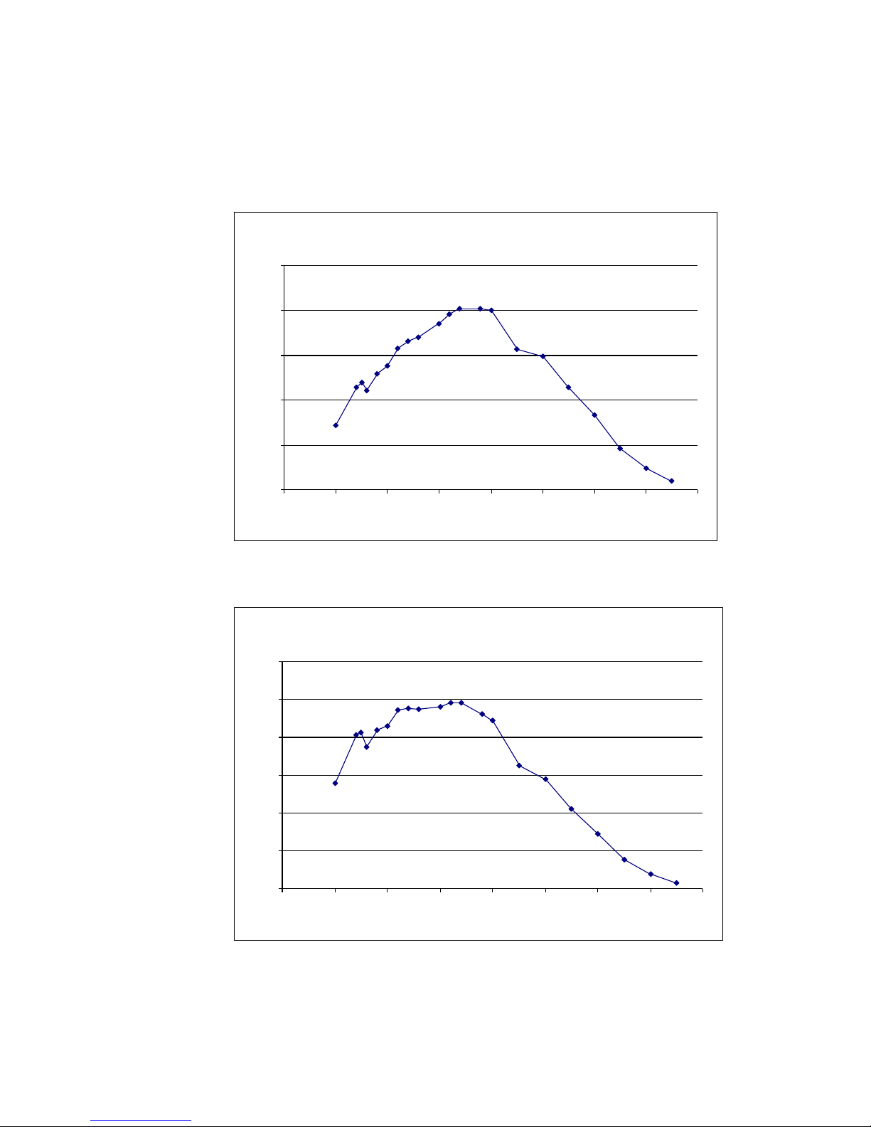
Spectral Responsivity at Coarse Gain = 0 dB, Fine Gain = 45
0
5
10
15
20
25
300 400 500 600 700 800 900 1000 1100
Wavelength (nm)
Responsivity (DN/(nJ/cm
2
))
Effective Quantum Efficiency
0
10
20
30
40
50
60
300 400 500 600 700 800 900 1000 1100
Wavelength (nm)
Fill Factor x Quantum Efficiency (%)
1.5 Responsivity
Figure 5: Spectral Responsivity (Monochrome Sensor)
Note: Responsivity is calibrated w ith fcc on .
Figure 6: Effective Quantum Efficiency (Monochrome Sensor)
Teledyne DALSA 03-032-20044-03
Falcon 4M Camera Manual
14
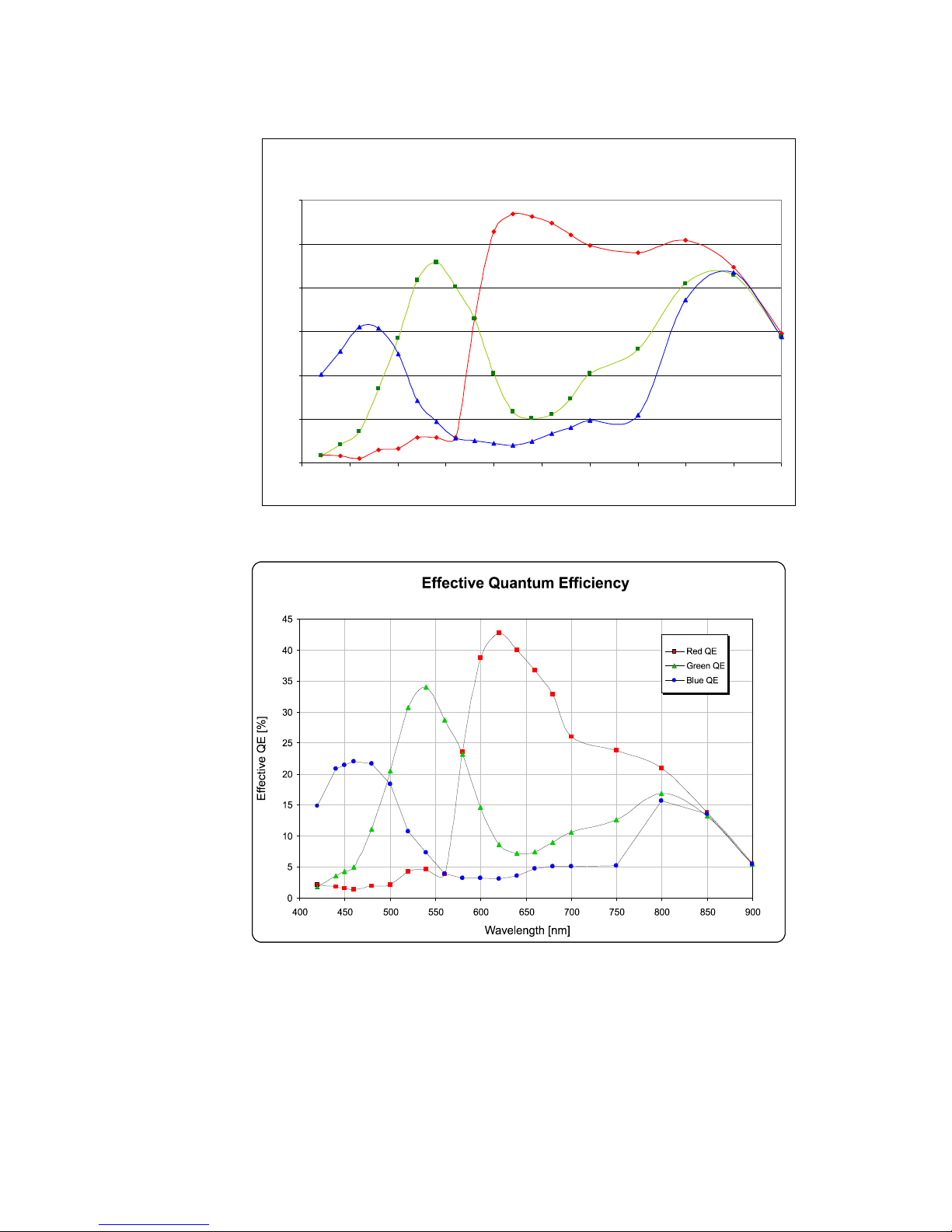
Avg spectral responsivity, 3 colour sensors
B=blue, R=red, G=green
0
2
4
6
8
10
12
400 450 500 550 600 650 700 750 800 850 900
Wavelength (nm)
Responsivity DN/(nJ/cm2)
Figure 7: Spectral Responsivity
Figure 8: Effective Quantum Efficiency
Note: We recommend you use of an SP700 IR-filter to remove unwanted IR signal that
could affect color reproduction.
03-032-20044-03 Teledyne DALSA
Falcon 4M Camera Manual
15
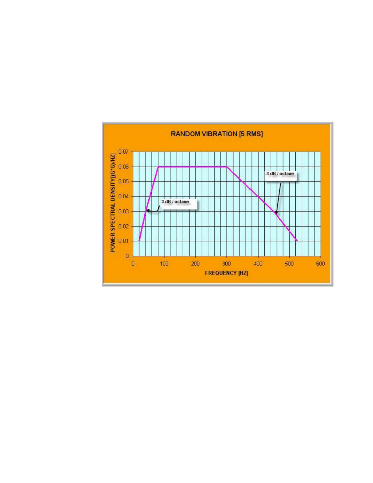
Random vibration per MIL-STD-810F at 25 G2/HZ [Power Spectral Density] or 5 RMS
Shock testing 75 G peak acceleration per MIL-STD-810F
Ambient Temperature
MTBF
40 °C
>65,000 hour
50 °C
>40,000 hours
1.6 Shock and Vibration
The Falcon 4M60 and 4M30 cameras are shock and vibration tested to ensure that they can
withstand the challenges and thrive in an industrial settings.
The cameras meet or exceed the following specifications:
The cameras meet the following Mean Time Before Failure (MTBF) specifications:
As shown, MTBF is highly dependant upon temperature. To improve MTBF reduce the
ambient temperatures, by using or increasing heat sinking or cooling of the camera. MTBF
is related to temperature. At lower temperatures MTBF numbers increase significantly. It
is recommended that if high MTBF numbers are demanded by your application you
include some type of cooling in your system, such as, forced air.
Teledyne DALSA 03-032-20044-03

Falcon 4M Camera Manual
16
03-032-20044-03 Teledyne DALSA

Falcon 4M Camera Manual
17
This installation
overview assumes you
have not installed any
system components yet.
Camera Hardware
Interface
2.1 Installation Overview
2
When setting up your camera, you should take the following steps:
1) Power down all equipment.
2) Following the manu facturer‘s instru ctions, in stall the fram e grabber (if ap plicable). Be
sure to observe all static precautions.
3) Install any necessary imaging software.
4) Before connecting power to the camera, test all power supplies.
5) Inspect all cables and connectors prior to installation. Do not use damaged cables or
connectors. The camera may be damaged as a result.
6) Connect Camera Link and power cables.
7) After connecting cables, apply power to the camera.
8) Check the diagnostic LED. If the camera is operating correctly, the LED will flash for
approximately 30 seconds and then turn solid green. See 2.2.1 LED Status Indicator
for a description of LED states.
You must also set up the other components of your system, including light sources,
camera mounts, computers, optics, encoders, and so on.
A note on Camera Link cable quality and length
The maximum allowable Camera Link cable length depends on the quality of the cable
used and the Camera Link strobe frequency. Cable quality degrades over time as the cable
is flexed. As the Camera Link strobe frequency is increased, the maximum allowable cable
length will decrease.
Imaging performance may be compromised if you use low quality cables of any length. In
general, use high quality cables in lengths less than 10 meters.
Teledyne DALSA 03-032-20044-03
Falcon 4M Camera Manual
18
Camera Link (Base Configuration)
Camera Link (Medium Configuration)
Diagnostic LED
+12V to +15V
CONTROL
DATA 1
DATA 2
POWER
Color of Status LED
Meaning
Flashing Green
Camera initialization or executing a time consuming command
Solid Green
Camera is operational and functioning correctly
Flashing Red
Fatal Error. System voltage out of tolerance.
Solid Red
Warning. Loss of functionality (e.g. external SRAM failure)
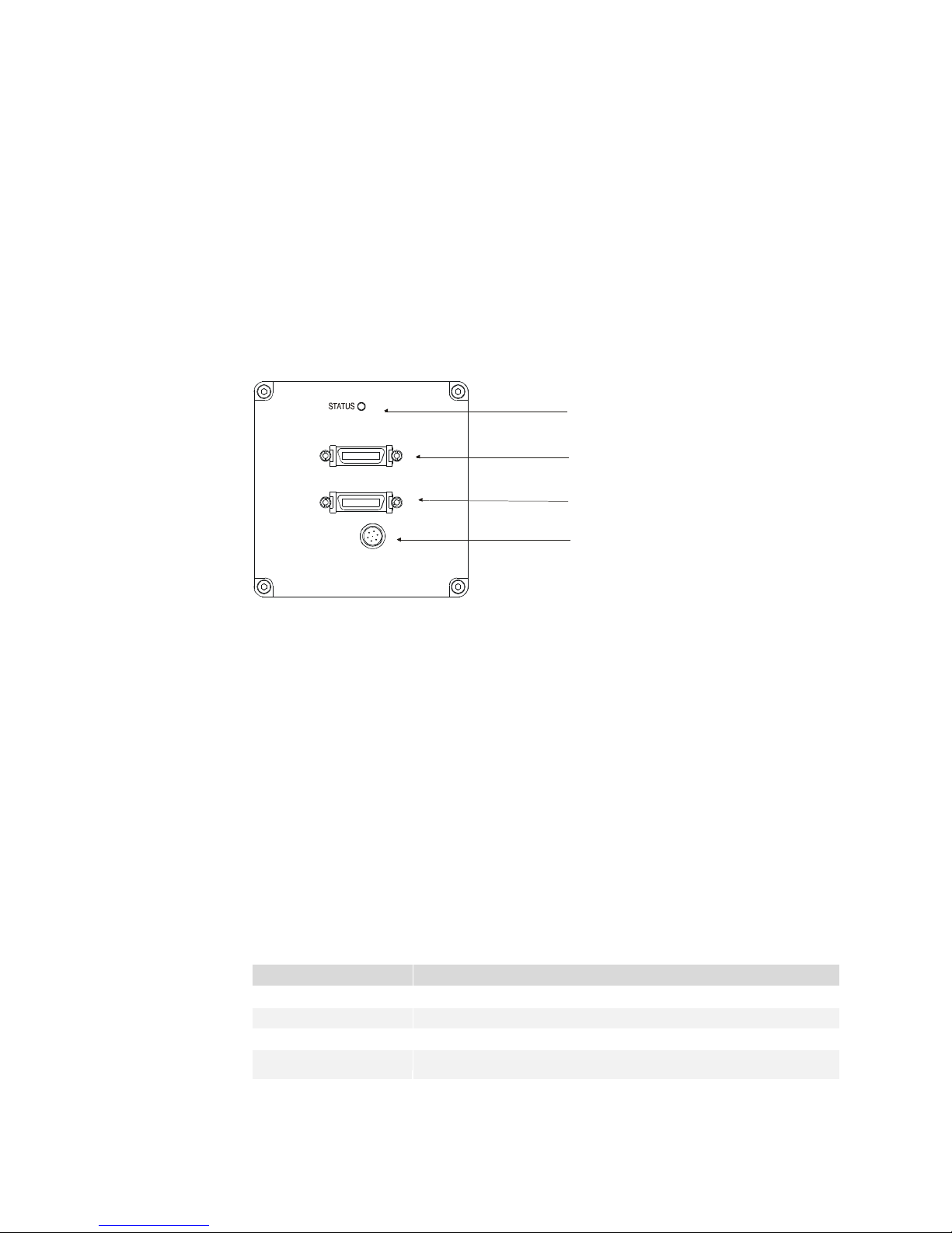
2.2 Input/Output Connectors and LED
The camera uses:
A diagnostic LED for monitoring the camera. See LED Status Indicator in section 2.2.1
LED Status Indicator for details.
Two high-density 26-pin MDR26 connectors for Camera Link control signals, data
signals, and serial communications. Refer to section 2.2.2 Camera Link
Data Connector for details.
One 6-pin Hirose connector for power. Refer to section 2.2.3 Power Connector for
details.
Figure 9: Input and Output
WARNING:
Ensure that all the correct voltages at full load are present at the camera power connector
(irrespective of cable length) according to the pinout defined in section 2.2.3 Power
Connector. A common system problem is that the voltage drop across the power cable is
large enough that the voltage at the camera does not meet the power input voltage
specifications.
2.2.1 LED Status Indicator
The camera is equipped with a red/ green LED used to display the operational status of
the camera. The table below summarizes the operating states of the camera and the
corresponding LED states.
When more than one condition is active, the LED indicates the condition with the highest
priority. Error and warning states are accompanied by corresponding messages further
describing the current camera status.
Status LED
03-032-20044-03 Teledyne DALSA
Falcon 4M Camera Manual
19
Configuration
8 Bit Ports
Supported
Serializer
Bit Width
Number
of Chips
Number of MDR26
Connectors
Base
A, B, C
28 1 1
Medium
A, B, C, D, E, F
28 2 2
BASE
Configuration
Port Definition
Mode (set with
clm command)
Port A
Bits 0 thru 7
Port B
Bits 0 thru 7
Port C
Bits 0 thru 7
Mode 2
2 Tap 8 bit
Tap 1 LSB..Bit 7
Tap 2 LSB..Bit7
xxxxxxx
Mode 3
2 Tap 10 bit
Tap 1 LSB.. Bit 7
Tap 1 Bits 8,9
Tap 2 Bits 8,9
Tap 2 LSB..Bit 7
Medium
Configuration
Port Definition
Mode
Port A
Bits 0 thru
7
Port B
Bits 0 thru
7
Port C
Bits 0 thru
7
Port D
Bits 0
thru 7
Port E
Bits 0
thru 7
Port F
Bits 0
thru 7
Mode 15
4 Tap 8 bit
Tap 1
LSB...Bit 7
Tap 2
LSB...Bit 7
Tap 3
LSB...Bit 7
Tap 4
LSB...Bit 7
xxxxxxxx
xxxxxxxx
Mode 16
4 Tap 10 bit
Tap 1
LSB...Bit 7
Tap 1 Bits 8,9
Tap 2 Bits 8,9
Tap 2
LSB...Bit 7
Tap 4
LSB…Bit 7
Tap 3
LSB…Bit
7
Tap 3 Bit
8,9
Tap 4 Bit
8,9
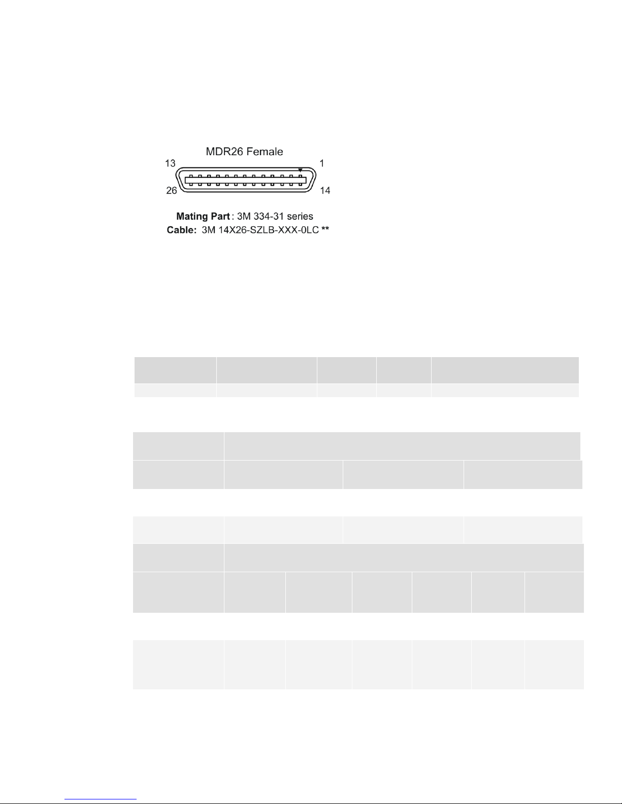
2.2.2 Camera Link
Data Connector
Figure 10: Camera Link MDR26 Connector
The Camera Link interface is implemented as either Base or Medium configuration in the
Falcon 4M cameras.
Select the camera configuration with the clm command described in the section Setting
the Camera Link Mode.
The following tables provide this cam era‘s p rin cip al Camer a Link information. See
Appendix A for the complete Camera Link configuration table, and refer to the
Knowledge Center on our Web site, here, for links to the official Camera Link documents.
Camera Link Hardware Configuration Summary
Teledyne DALSA 03-032-20044-03

Falcon 4M Camera Manual
20
Medium Configuration
Base Configuration
Up to an additional 2 Channel Link Chips
One Channel Link Chip + Camera
Control + Serial Communication
Camera
Connector
Right Angle
Frame Grabber
Connector
Channel Link
Signal
Camera
Connector
Right Angle
Frame
Grabber
Connector
Channel
Link Signal
1 1 inner shield
1 1
inner shield
14
14
inner shield
14
14
inner shield
2
25
Y0- 2
25
X0-
15
12
Y0+ 15
12
X0+ 3 24
Y1- 3
24
X1-
16
11
Y1+ 16
11
X1+ 4 23
Y2- 4
23
X2-
17
10
Y2+ 17
10
X2+ 5 22
Yclk-
5 22
Xclk-
18 9 Yclk+
18 9 Xclk+
6
21
Y3- 6
21
X3-
19 8 Y3+ 19 8 X3+ 7 20
100 ohm
7 20
SerTC+
20 7 terminated
20 7 SerTC-
8
19
Z0- 8
19
SerTFG-
21 6 Z0+ 21 6 SerTFG+
9
18
Z1- 9
18
CC1-
22 5 Z1+ 22 5 CC1+
10
17
Z2- 10
17
CC2+
23 4 Z2+ 23 4 CC2-
11
16
Zclk-
11
16
CC3-
24 3 Zclk+
24 3 CC3+
12
15
Z3- 12
15
CC4+
25 2 Z3+ 25 2 CC4-
13
13
inner shield
13
13
inner shield
26
26
inner shield
26
26
inner shield
Signal
Configuration
CC1
EXSYNC
CC2
Reserved for future use
CC3
Reserved for future use
CC4
Window toggle
Camera Link Connector Pinout
Notes:
*Exterior Overshield is connected to the shells of the connectors on both ends.
**3M part 14X26-SZLB-XXX-0LC is a complete cable assembly, including connectors.
Unused pairs should be terminated in 100 ohms at both ends of the cable.
Inner shield is connected to signal ground inside camera
Camera Control Configuration
03-032-20044-03 Teledyne DALSA

Falcon 4M Camera Manual
21
!
Clocking Signal
Indicates
LVAL (high)
Outputting valid line
DVAL (high)
Valid data
STROBE (rising edge)
Valid data
FVAL (high)
Outputting valid frame
Hirose Pin Description
Pin
Description
Pin
Description
1
12 to 15V
4
GND
2
12 to 15V
5
GND
3
12 to 15V
6
GND
IMPORTANT:
Camera readout is
triggered on the falling
edge of EXSYNC.
Input Signals, Camera Link
The camera accepts control inputs through the Camera Link MDR26F connector.
The camera ships in internal sync, internal programmed integration (exposure mode 2),
and Camera Link mode 16 (4M60) or 3 (4M30).
EXSYNC
Frame rate can be programmed using the serial interface. The external control signal
EXSYNC is optional and enabled through the serial interface. This camera uses the falling
edge of EXSYNC to trigger frame readout. Section 3.3 Camera Output Format details
how to set frame times, exposure times, and camera modes.
Output Signals, Camera Link
These signals indicate when data is valid, allowing you to clock the data from the camera
to your acquisition system. These signals are part of the Camera Link configuration and
you should refer to the Camera Link Implementation Road Map, available from the
Knowledge Center on our Web site, here, for the standard location of these signals.
The camera internally digitizes to 10 bits and outputs 8 MSB or all 10 bits depending
on the ca m era‘s Ca m era Lin k operating mode.
For a Camera Link reference and timing definitions refer to Appendix A on page 73.
2.2.3 Power Connector
Figure 11: Hirose 6-pin Circular Male—Power Connector
The camera requires a single voltage input (+12 to +15V).
WARNING: When setting up the camera’s power supplies follow these guidelines:
Protect the camera with a fast-blow fuse between power supply and camera.
Power surge limit at 3 A.
12 V power supply. Nominal 0.85 A load resulting in ~ 20 A/ s current ramp rate
Power supply current limit needs to be set at > 3 A.
Teledyne DALSA 03-032-20044-03
Do not use the shield on a multi-conductor cable for ground.

Falcon 4M Camera Manual
22
!
Keep cables as short as possible to reduce voltage drop. Long power supply leads
may falsely indicate that the power supply is within the recommended voltage range
even when the camera at the connector is actually being sup plied with much less
voltage.
Use high-quality linear supplies to minimize noise.
Use an isolated type power supply to prevent LVDS common mode range violation.
Note: Performance specifications are not guaranteed if your power supply does not meet
these requirements.
WARNING: It is extremely important that you apply the appropriate voltages to your
camera. Incorrect voltages will damage the camera. Protect the camera with a fast-blow
fuse between power supply and camera.
03-032-20044-03 Teledyne DALSA

Falcon 4M Camera Manual
23
Software Interface: How
to Control the Camera
All camera features can be controlled through the serial interface. The camera can also be
used without the serial interface after it has been set up correctly. Functions available
include:
3
Controlling basic camera functions such as gain and sync signal source
Data readout control
Generating a test pattern for debugging
The serial interface uses a simple ASCII-based protocol and the camera does not
require any custom software.
Serial Protocol Defaults
8 data bits
1 stop bit
No parity
No flow control
9.6 Kbps
Camera does not echo characters
Command Format
When entering commands, remember that:
A carriage return <CR> ends each command.
The camera will answer each command with either <CR><LF> OK > or Error x:
Error Message >. The > is always the last character sent by the camera.
The camera accepts both upper and lower case commands.
The following parameter conventions are used in the manual:
i = integer value
f = real number
m = member of a set. Value must be entered exactly as displayed on help screen.
Teledyne DALSA 03-032-20044-03

Falcon 4M Camera Manual
24
Purpose:
Sets the speed in bps of the serial communication port.
Syntax:
sbr m
Syntax Elements:
m
Baud rate. Available baud rates are: 9600 (Default), 19200,
57600, and 115200.
Notes:
Power-on rate is always 9600 baud.
The rc (reset camera) command will not reset the camera to
the pow er-on baud rate and will reboot using the last used
baud rate.
Example:
sbr 57600
Syntax:
h
s = string
t = tap id
x = pixel column number
y = pixel row number
Example: to retrieve the current camera settings
gcp <CR>
Setting Baud Rate
Camera Help Screen
For quick help, the camera can retrieve all available commands and parameters through
the serial interface.
To view the help screen, use the command:
The help screen lists all commands available. Parameter ranges displayed are the ranges
available under the current operating conditions. The ranges depend on the current
camera operating conditions, and you may not be able to enter these values.
03-032-20044-03 Teledyne DALSA

Falcon 4M Camera Manual
25
ccf correction calculate fpn
clm camera link mode m 2/ 3/ 15/ 16/
cpa correction prnu algorithm mi 2/ 4/ :1-1023
csn coefficient set number i 0-5
css correction set sample m 32/ 64/ 128/ 256/ 512/ 1024/
dpc display pixel coefficients xyxy 1-2352:1-1728:1-2352:1-1728
edc enable debounce circuit m 0/ 1/
efd enable frame dump m 0/ 1/ 2/
epc enable pixel coefficients ii 0-1:0-1
gcm get camera model
gcp get camera parameters
gcs get camera serial
gcv get camera version
gfc get fpn coefficient xy 1-2352:1-1728
gpc get prnu coefficient xy 1-2352:1-1728
gsf get signal frequency m 1/ 4/
h help
lpc load pixel coefficient
rc reset camera
rfs restore factory settings
rpc reset pixel coefficients
rus restore user settings
sao set analog offset ti 0-0:0-511
sbr set baud rate m 9600/ 19200/ 57600/ 115200/
sdo set digital offset ti 0-2:0-2048
sem set exposure mode m 2/ 3/ 4/ 6/ 7/
set set exposure time f 10-999989 [us]
sfc set fpn coefficient xyi 1-2352:1-1728:0-1023
snd set number frame dumps i 1-7
sot set output throughput m 260/ 320/
spc set prnu coefficient xyi 1-2352:1-1728:0-28671
spm set prnu multiplier m 4/ 8/ 16
ssb set subtract background ti 0-4:0-511
ssf set sync frequency f 1.0-62.2 [Hz]
ssg set system gain ti 0-4:0-65535
svm set video mode i 0-12
tpv test pattern value m 63/ 127/ 255
vt verify temperature
vv verify voltages
wfc write fpn coefficients
wpc write prnu coefficients
wse window start end iixyxy 0-0:1-1:1-1:1-1725:2352-2352:4-1728
wss window set sequence i 0-1
wts window trigger source m 1/ 2/
wus write user settings
Example Help Screen (4M60)
Teledyne DALSA 03-032-20044-03
OK>

Falcon 4M Camera Manual
26
Syntax:
gcp
Retrieving Camera Settings
To retrieve current camera settings, use the command:
3.1 First Power Up Camera Settings
When the camera is powered up for the first time, it operates using the following factory
settings:
PT-4x-04M60
Flat field coefficients enabled (calibrated in exposure mode 2, 55 fps, and an
exposure time of 2 ms [non-concurrent readout and integration], snapshot mode
1, number of fast frame dumps = 1)
Exposure mode 2
60 fps
9995 µs exposure time
Camera Link mode 16 (Medium configuration, 4 taps. 10 bits)
80 MHz pixel rate (320 MHz total throughput)
Full window (2352 x 1728)
Snapshot mode 1 enabled (EFD 1)
PT-2x-04M30
Flat field coefficients enabled (calibrated in exposure mode 2, 29 fps, and
exposure time of 2 ms [non-concurrent readout and integration], snapshot mode
1, number of fast frame dumps = 1)
Exposure mode 2
30 fps
14992 µs exposure time
Camera Link mode 3 (Medium configuration, 2 taps. 10 bits)
80 MHz pixel rate (160 total throughput)
Full window (2352 x 1728)
Snapshot mode 1 (EFD 1)
03-032-20044-03 Teledyne DALSA
Falcon 4M Camera Manual
27
Factory
Settings
Current
Session
wus
rus
rfs
User
Settings
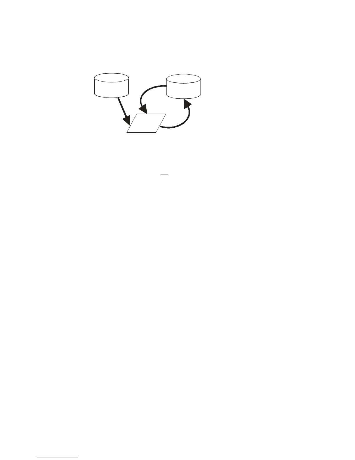
3.2 Saving and Restoring Settings
Figure 12: Saving and Restoring Overview
Factory Settings
You can restore the original factory settings at any time using the command rfs.
Note: This command does not restore flat field coefficients. Refer to the lpc command.
User Settings
You can save or restore your user settings to non -volatile memory using the following
commands.
To save all current user settings to non-volatile memory, use the command wus. The
camera will automatically restore the saved user settings when powered up.
To restore the last saved user settings, use the command rus.
Note: on power-up the camera will restore the FFC coefficients where csn is pointing to.
Example:
csn 1 (and choose coeff set 1)
wus
rc or power cycle
Coefficients from csn 1 are restored
Current Session Settings
These are the current operating settings of your camera. These settings are stored in the
cam era‘s volatile m em ory and w ill n ot be restored once y ou p ow er d ow n your cam era or
issue a reset camera command (rc). To save these settings for reuse at power up, use the
command wus.
3.3 Camera Output Format
3.3.1 How to Configure Camera Output
The 4M Falcon cameras offer great flexibility when configuring your camera output.
Using the clm comm a n d , you d eterm in e the cam era‘s Cam era Lin k configuration,
Teledyne DALSA 03-032-20044-03

Falcon 4M Camera Manual
28
Camera Link Mode Configuration
(Controlled by clm command)
Pixel Rate
Configuration
(Controlled by
sot command)
Command
Camera Link
Configuration
Camera Link Taps
Bit
Depth
clm 2
Base
2 Camera Link taps
where:
1 = Taps 1+3
2 = Taps 2+4
8
sot 130 = 65
MHz strobe
sot 160 = 80
MHz strobe
clm 3
Base
2 Camera Link taps
where:
1 = Taps 1+3
2 = Taps 2+4
10
sot 130 = 65
MHz strobe
sot 160 = 80
MHz strobe
number of output taps, and bit depth. Using the sot command, you determine the
cam era‘s outpu t rat e. These tw o com mand s work tog eth er to d etermin e you r fin a l cam era
output configuration.
4M30 Data Readout Configurations
03-032-20044-03 Teledyne DALSA
 Loading...