

Page 1
MA Series Service Manual
Grade 1 Mortise Lever and Knob Locks
Page 2

Page 3

MA-Series Service Manual
Table of Contents
Introduction ......................................................ii
Functions .........................................................2
MA101 - Passage or Closet Latch .............5
MA161 - Exit or Communicating Lock ......6
MA301 - Privacy, Bedroom/Bath ................7
MA311 - Privacy, Bedroom/Bath ................8
MA321 - Privacy, Bedroom/Bath ................9
MA371 - Store Door Lock .........................10
MA381 - Apartment, Exit ..........................11
MA411 - Asylum or Institutional Lock .....12
MA431 - Intruder Dead Bolt Lock ............13
MA441 - Intruder Latch Bolt Lock ...........14
MA451 - Hotel Guest Lock .......................15
MA521 - Entry Lock ..................................16
MA531 - Apartment Corridor Door Lock .17
MA541 - Entry/Office Lock ....................... 18
MA551 - Holdback Lock............................19
MA561 - Classroom Lock .........................20
MA571 - Dormitory or Exit Lock ..............21
MA581 - Storeroom / Closet Lock............22
MA621 - Front Door / Apartment
Corridor .....................................................23
MA641 - Dormitory Lock ..........................24
MA851 - Electrified EL - 12 & 24 VDC (Fail
Safe) ........................................................... 25
MA881 - Electrified EU - 12 & 24 VDC (Fail
Secure) .......................................................26
MA911 - Classroom Dead Lock ...............27
MA921 - Dead Lock ...................................28
MA931 - Dead Lock ...................................29
MA941 - Dead Lock ...................................30
MA12 - Single Dummy ..............................31
MA18 - Double Dummy .............................32
Knob and Lever Designs ..............................33
MA-Series Screw Packs ................................34
Strikes .............................................................36
Cams ............................................................... 37
Mortise, Rim and Cam Lock for Standard
Cylinders ........................................................39
Cylinder Collars ............................................. 40
Trim Rings & Collars .....................................41
Electrically Locking ....................................... 42
Ordering Procedures .....................................43
Installation Instructions ................................44
i
Page 4
Introduction
MA-Series Service Manual
Introduction
This manual contains a complete listing of parts and assemblies for MA-Series mortise locks manufactured by Falcon
Lock Company. This edition lists components of MA-Series locks manufactured after June, 2010. All lock case covers
are labeled with dates to identify year of manufacture. Example: 12507 = the 125th day of 2007.
Exploded views of each lock function and trim assembly are provided with accompanying charts to identify parts for
replacement purposes. Exploded views of trim are shown with parts for standard size doors. In addition, this manual
provides lock trim ordering procedures, cylinder length charts by door range, and all auxiliary components of the MASeries mortise locks.
Standard Features*
Certifications ANSI A156 .13, Series 1000, Grade 1 Operation and Security, UL Listed for 3-hour fire door
Latch
Strike
Cylinder 6-Pin solid brass, keyed 5-pin, Falcon G keyway, keyed different (KD)
Door Range
Keys Two, nickel silver cut keys per lock, Falcon G keyway
Backset
* Locks are furnished with standard features unless otherwise specified.
2-piece brass mechanical anti-friction bolt, ³⁄₄” projection
1¹⁄₄” x 4⁷⁄₈”, ANSI, Square corner, with dust box
1³⁄₈” – 2¹⁄₂” standard
2³⁄₄”
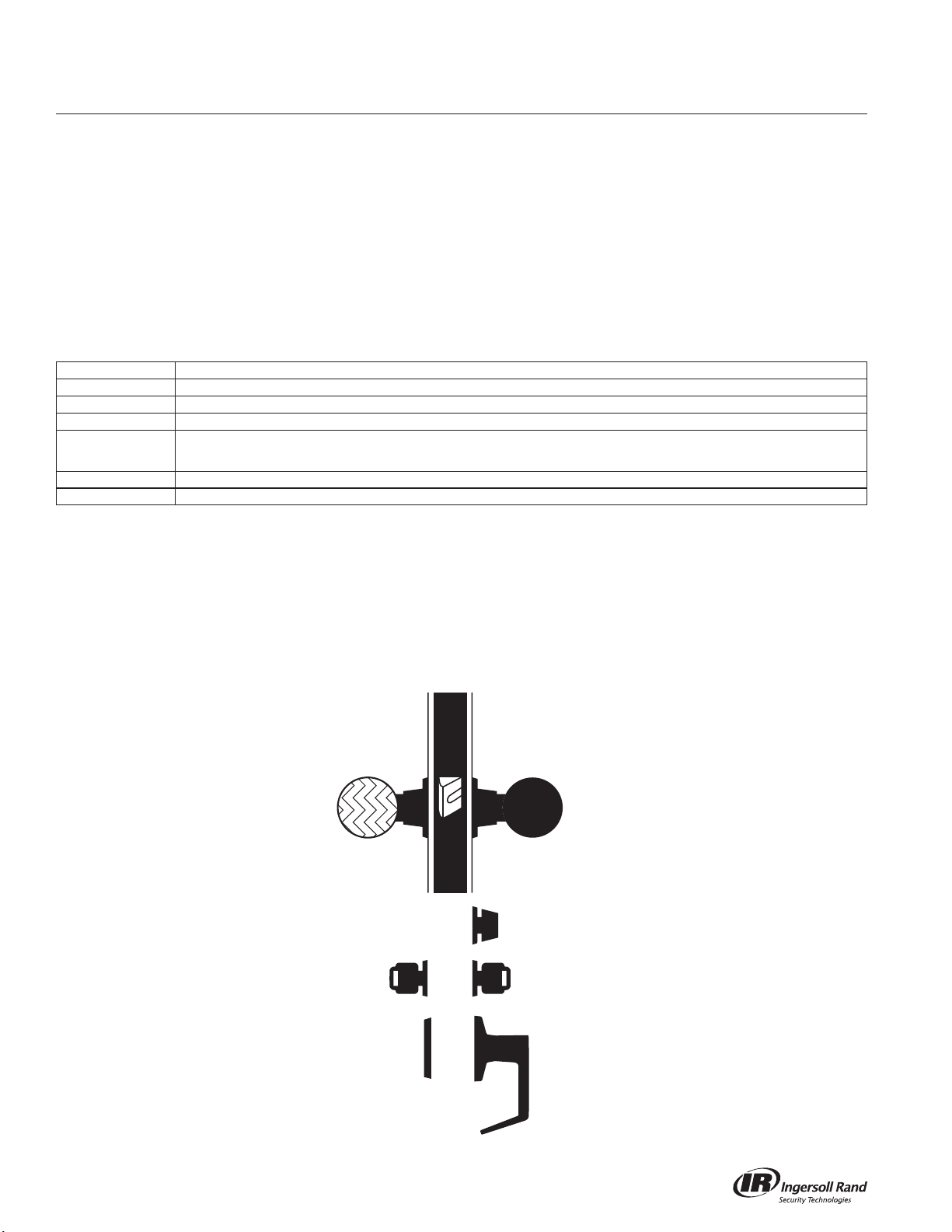
Lock Assembly Drawing Index
The Lock Assembly Drawing Index provides visual representations and textual descriptions of available functions.
Page numbers for full trim and chassis drawings are referenced.
Rigid Knob
Key
Blank Plate
Knob
T-Turn
Key
Lever
ii
Page 5
MA-Series Service Manual
7
6
Introduction
8
9
12
3
5
10
4
12
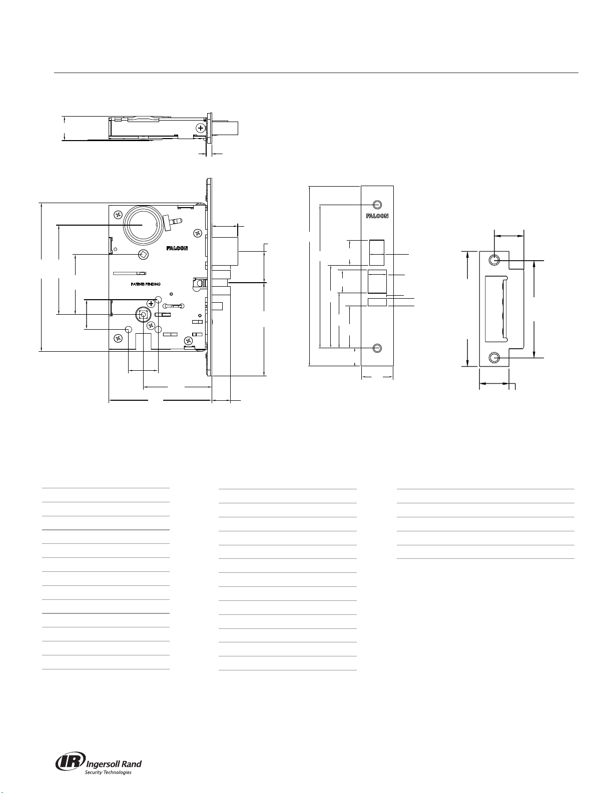
Lock Faceplate Strike
13
Lock Dimension
1 6” (152mm)
2 3-39/64” (92mm)
3 2-27/64” (62mm)
4 1-3/16” (30mm)
5 1-3/16” (30mm)
6 1/4” (6mm)
7 1” (25mm)
8 1” (25mm)
9 1-17/64” (32mm)
10 3-49/64” (96mm)
11 3/4” (19mm)
12 2-3/4” (70mm)
13 4-5/32” (106mm)
11
Faceplate Dimension
14 8” (203mm)
15 6-3/8” (162mm)
16 9/16” (14mm)
17 1-9/64” (29mm)
18 45/64” (18mm)
19 1-1/32” (26mm)
20 1/4” (6mm)
21 11/32” (9mm)
22 1-1/4” (32mm)
23 1-27/32” (47mm)
24 2-7/16” (62mm)
25 3-21/32” (93mm)
26 25/32” (20mm)
14
15
25
24
19
17
23
16
18
20
21
26
22
Strike
(A) Door Thickness Lip Size
1-3/4” – 1-7/8” 1-1/4” (32mm)
2” – 2-1/8” 1-7/16” (37mm)
2-1/4” – 2-3/8” 1-9/16” (40mm)
2-1/2” – 2-5/8” 1-11/16” (43mm)
4-7/8"
(124mm)
A
4-1/8"
(105mm)
1-1/4"
(32mm)
1
Page 6
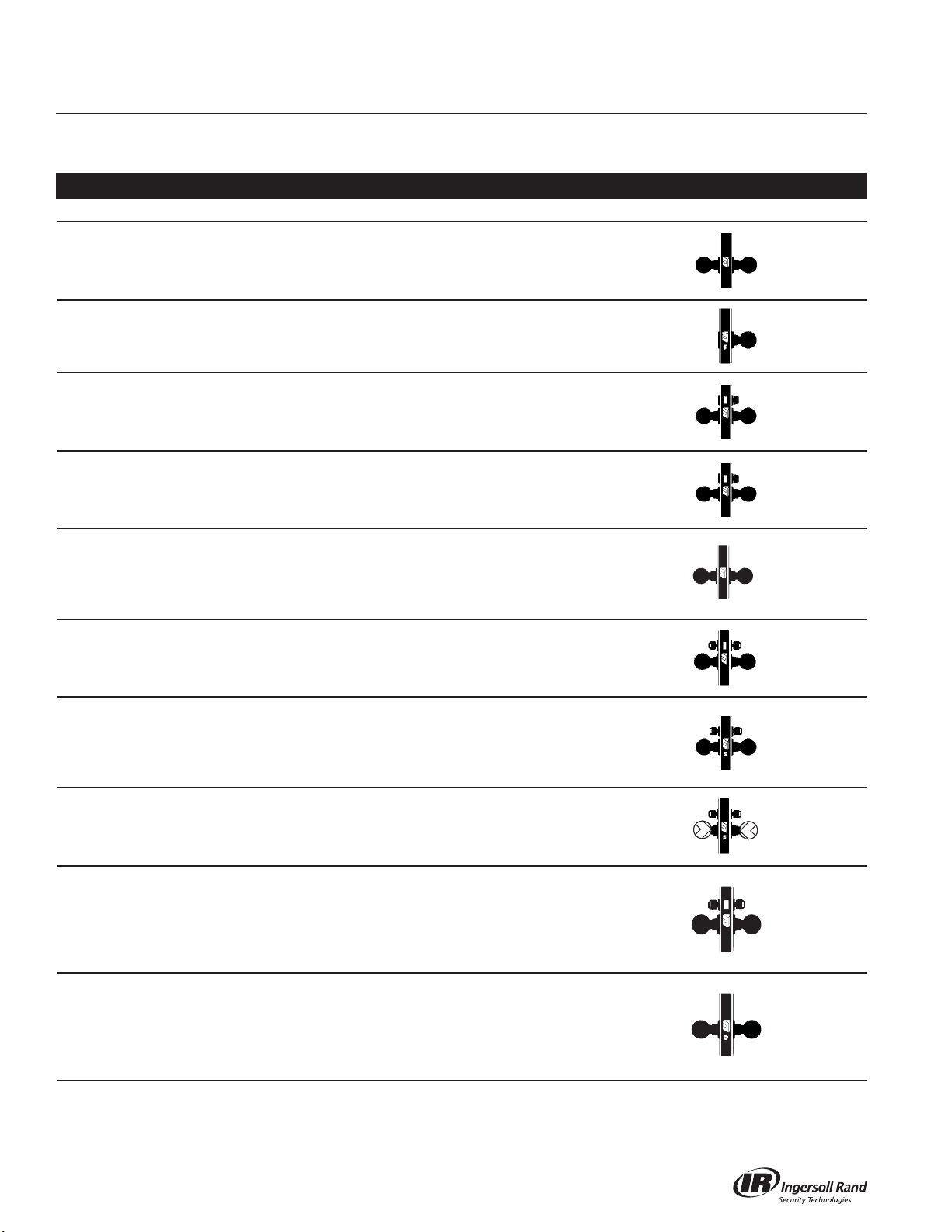
Functions
MA-Series Service Manual
To order Falcon MA-Series locksets, please consult page 43 for ordering information and assistance.
Catalog Number Prefixes: Add the following prefix for the appropriate trim style.
Function ANSI A156.13, 2005 Page
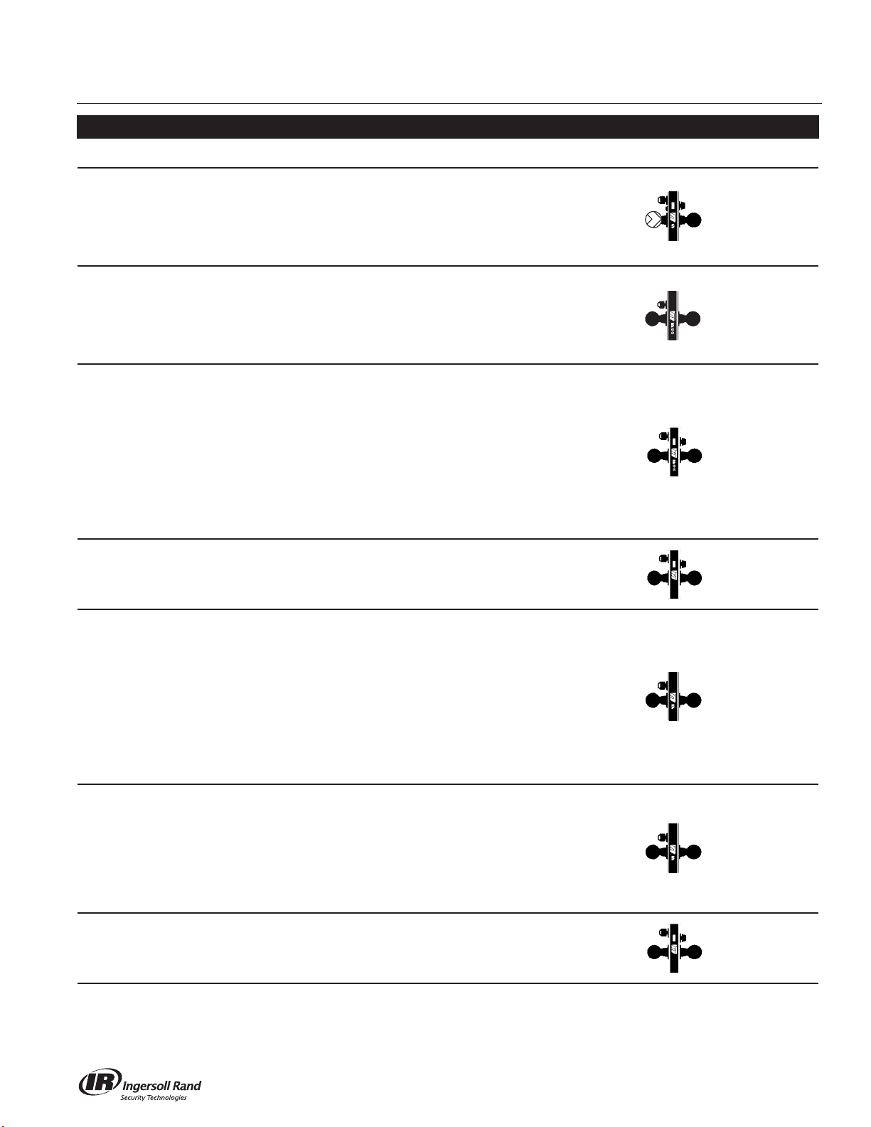
SCHLAGE ANSI DESCRIPTION FUNCTION
MA101 F01
MA161 F31
MA301 F02 Privacy Lock
MA311 F19
MA321 F22 Privacy Lock
MA371 F14
Passage/Closet
Latchset
Connecting
Room/Exit
Latch
Privacy,
Bedroom or
Bath Lock
Store Door
Lock
Latch bolt by knob/levers at all times.
Latch bolt operated by knob/lever from inside. No
trim outside. Auxiliary dead latch.
Latch bolt by knobs/levers either side, dead bolt by
turn inside or emergency release outside.
Latch bolt by knobs/levers. Deadbolt by turn from
inside and emergency release outside. Rotating
inside knob/lever retracts both bolts.
Latch bolt operated by knob/lever from either side
except when outside knob/lever is locked by inside
T-turn. Operating inside knob/lever, closing door
or operating outside emergency release unlocks
outside knob/lever.
Latch bolt by knobs/levers. Deadbolt by key from
either side. Throwing deadbolt locks latchbot from
either side.
5
6
7
8
9
10
MA381 F09
MA411 F30 Asylum Lock
MA431 F34
MA441 F32
Apartment, Exit
Lock
Intruder
Deadbolt Lock
Intruder
Latchbolt Lock
Latch bolt operated by knob/lever from either side,
except when outside knob/lever is locked by key
from inside. When outside knob/lever is locked,
latch bolt is retracted by key from outside or by
operating inside lever. Auxiliary dead latch.
Latch bolt operated by key from either side. Both
knobs/levers always inoperative. Auxiliary dead
latch.
Latch bolt operated by knob/lever from either side
except when outside knob/lever is locked from
inside or outside by key. Dead bolt retracted by key
from inside or outside. Operating inside knob/lever
retracts both bolts and unlocks outside. Latch bolt
dead locked when dead bolt is thrown.
Latch bolt operated by knob/lever from either side
except when outside knob/lever is locked from
inside or outside by key. When outside knob/lever is
locked, latch bolt is retracted by key from inside or
outside or by operating inside knob/lever. Auxiliary
dead latch.
11
12
13
14
2
Page 7
MA-Series Service Manual
Function ANSI A156.13, 2005 Page
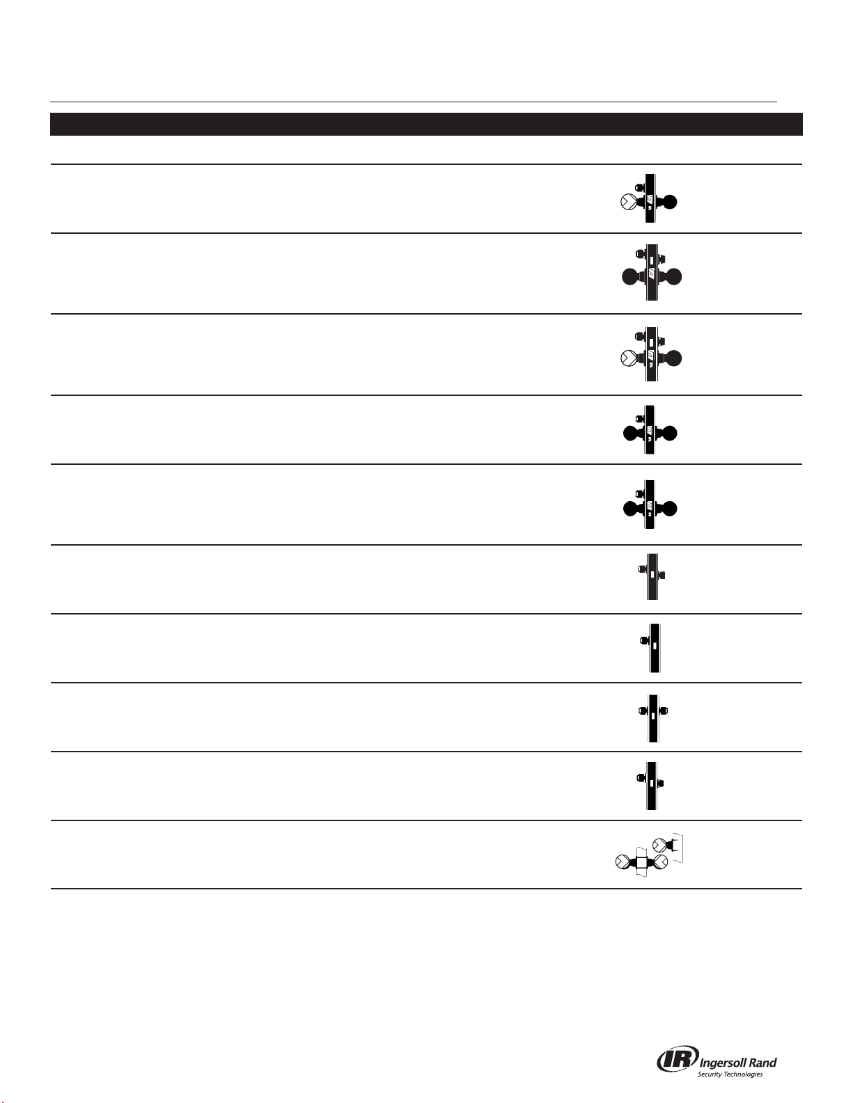
SCHLAGE ANSI DESCRIPTION FUNCTION
Latch bolt operated by key from outside or by
operating inside knob/lever. Outside knob/lever
MA451 F15 Hotel/Guest Lock
MA521 F04 Entry/Office Lock
Apartment
Corridor Door
Lock
MA531
F12,
F20
is always inoperative. Dead bolt projected by
turn from inside and all keys except emergency
key are shut out. Operating inside knob/lever
retracts both bolts. Auxiliary dead latch.
Latch bolt operated by knob/lever from either
side except when outside knob/lever is made
inoperative by buttons in face. When outside
knob/lever is locked, latch bolt is retracted by
key from outside or by operating inside knob/
lever. Auxiliary dead latch.
Latch bolt operated by knob/lever from either
side, except when outside knob/lever is made
inoperative by buttons in face. Dead bolt
operated by key outside or turn inside. Key
outside operates both bolts. Operating inside
knob/lever retracts both bolts and outside
remains locked. Latch bolt is deadlocked when
outside knob/lever is made inoperative or
when the dead bolt is projected. When dead
bolt is retracted, knob/lever is unlocked by
buttons in face.
Functions
15
16
17
MA541 F21 Entry/Office Lock
MA551 F06 Holdback Lock
MA561 F05 Classroom Lock
MA571 F13
Dormitory or Exit
Lock
Latch bolt by knobs/levers either side.
Deadbolt by key outside or turn inside.
Latch bolt operated by lever from either side
except when outside lever is locked from
outside by key. Latch bolt can be locked in a
retracted position by key. When outside lever
is locked, latch bolt is retracted by key from
outside or by operating inside lever unless
latch bolt has been locked in a retracted
position. Auxiliary dead latch. Activate/
Deactivate instructions on page
Note: Chassis is handed. For Holdback
Activation instructions see page 48.
Latch bolt operated by knob/lever from either
side except when outside knob/lever is locked
by key. When outside knob/lever is locked,
latchbolt is retracted by key from outside or
by operating inside knob/lever. Auxiliary latch
deadlocks latch bolt when door is closed.
Inside knob/lever always free for immediate
use.
Latch bolt operated by knob/lever from either
side. Dead bolt projected by key from outside
and turn from inside. Operating inside knob/
lever retracts both bolts and unlocks outside.
18
19
20
21
3
Page 8
Functions
MA-Series Service Manual
Function ANSI A156.13, 2005 Page
SCHLAGE ANSI DESCRIPTION FUNCTION
Latch bolt operated by key from outside or by
MA581 F07 Storeroom Lock
MA621
MA641 - Dormitory Lock
MA851 -
MA881 -
F08/
F10
Front Door/
Apartment
Corridor
Storeroom - Fail
Safe EL
Storeroom - Fail
Secure EU
operating inside knob/lever. Outside knob/lever
is always inoperative. Auxiliary dead latch.
Latch bolt is operated by knob/lever from either
side except when outside knob/lever is made
inoperative by buttons in face. Dead bolt is
operated by turn inside. Key outside operates
both bolts.
Latch bolt by knob/lever inside and key outside.
Inside knob/lever free. Outside knob/lever
rigid. Dead bolt by key outside or T-turn inside.
Rotating inside knob/lever retracts both bolts.
Deadlocking latch.
Latch bolt operated by knob/lever from either
side except when outer knob/lever is electrically
locked. When outer knob/lever is locked, latch
bolt retracted by key outside. Deadlocking latch.
Latch bolt operated by knob/lever from inside
except when outer knob/lever is electrically
unlocked, then latch bolt from either side.
When locked, key outside retracts latch bolt.
Deadlocking latch.
22
23
24
25
26
MA911 F29
MA921 F18 Deadlock Deadbolt by key outside only.
MA931 F16 Deadlock Deadbolt by key from either side. 29
MA941 F17 Deadlock Deadbolt by key outside or turn inside. 30
MA12/
MA18
Classroom
Deadlock
- Dummy Trim
Key from outside operates deadbolt. Turn from
inside retracts but does not project dead bolt.
Single or double available.
SIngle (MA12).
Double (MA18).
27
28
31
32
4
Page 9
MA-Series Service Manual
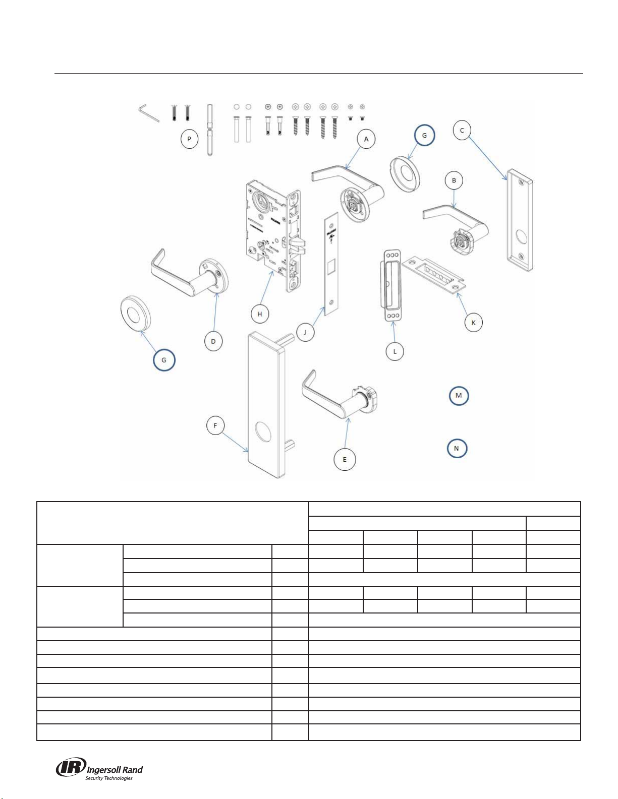
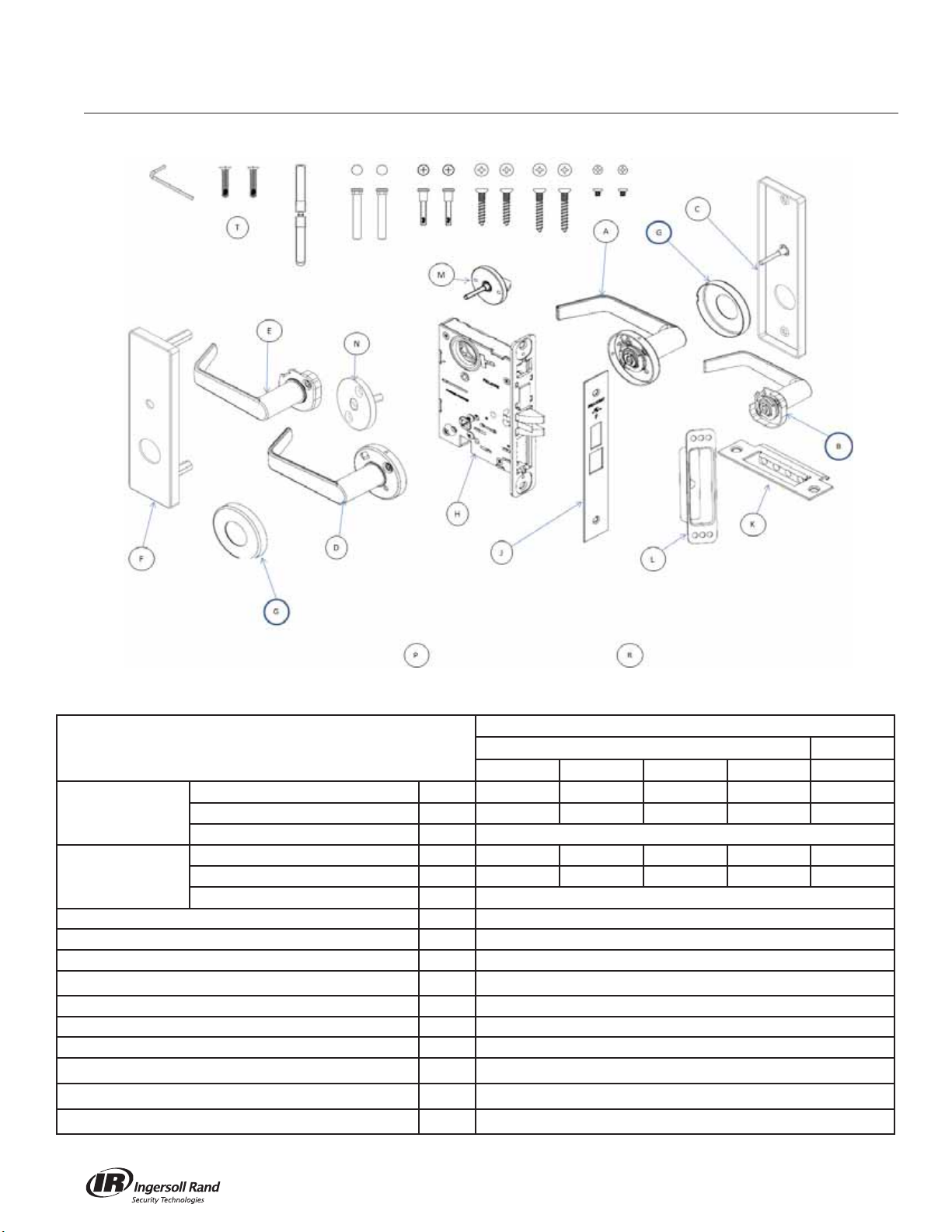
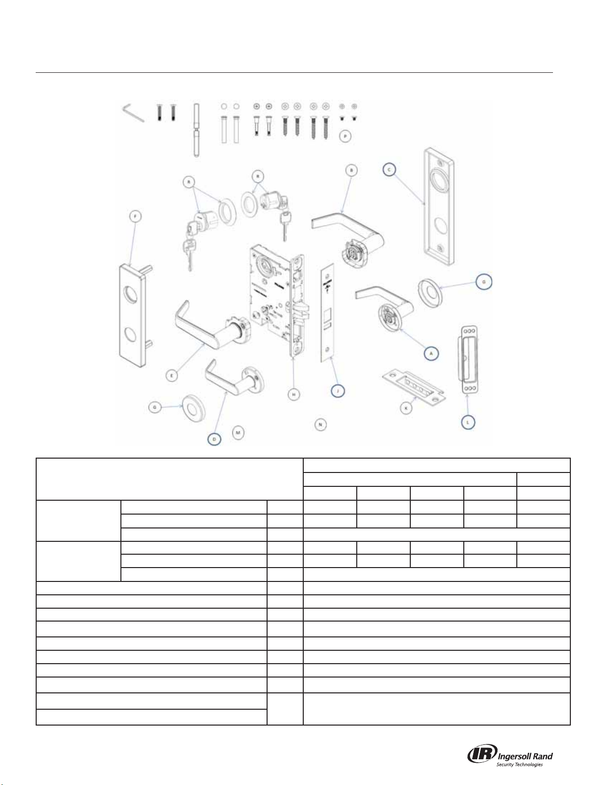
MA101 - Passage or Closet Latch
Trim
Lever Knob
Description
KNOB/LEVER SECTIONAL
INSIDE TRIM
OUTSIDE TRIM
ROSE (2 REQ'D) G S76012
ASSY, LOCK UNIT H A7801
FACEPLATE J S77801
STRIKE ASSY
STRIKE BOX L PE1396
DOOR MARKER M Q513-068
INSTRUCTION SHEETS N Q513-067
SCREW PACK
KNOB/LEVER ESCUTCHEON
ESCUTCHEON C E77012-IP
KNOB/LEVER SECTIONAL D AS76280 AS76526 AS76029 AS76140 AS76100
KNOB/LEVER ESCUTCHEON E AE77280 AE77526 AE77029 AE77140 AE77100
ESCUTCHEON
A
B
F
K
P
Dane Sutro Avalon Quantum Hana
AS76280 AS76526 AS76029 AS76140 AS76100
AE77280 AE77526 AE77029 AE77140 AE77100
AE77012-0P
A8737-1
See page 34
5
Page 10
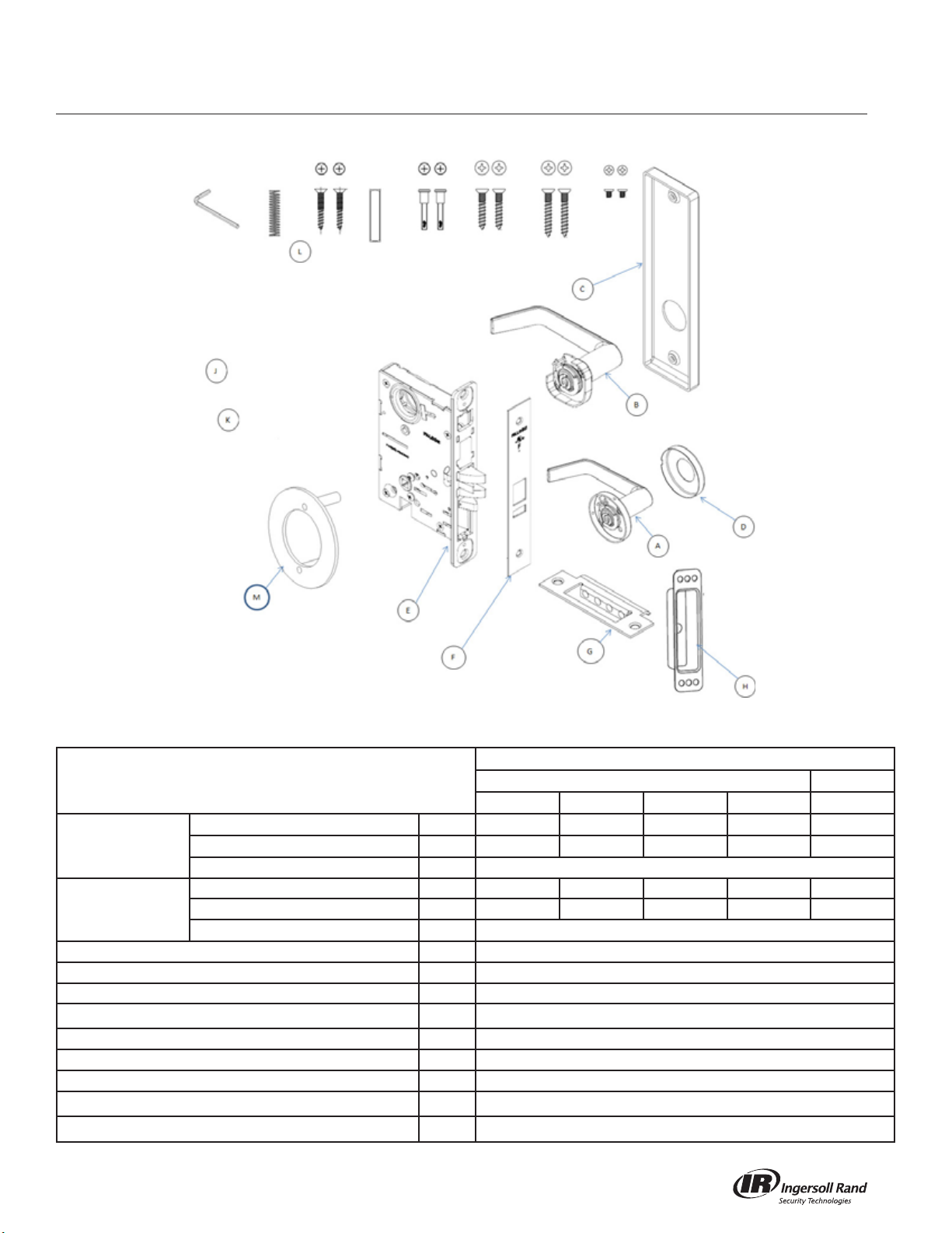
MA161 - Exit or Communicating Lock
MA-Series Service Manual
Trim
Lever Knob
Description
KNOB/LEVER SECTIONAL
INSIDE TRIM
OUTSIDE TRIM
ROSE D S76012
ASSY, LOCK UNIT E A7831
FACEPLATE F S77805
STRIKE ASSY
STRIKE BOX H PE1396
DOOR MARKER J Q513-068
INSTRUCTION SHEETS K Q513-067
SCREW PACK
PLATE M
KNOB/LEVER ESCUTCHEON
ESCUTCHEON C E77012-IP
KNOB/LEVER SECTIONAL - N/A N/A N/A N/A N/A
KNOB/LEVER ESCUTCHEON - N/A N/A N/A N/A N/A
ESCUTCHEON
A
B
-
G
L
Dane Sutro Avalon Quantum Hana
AS76280 AS76526 AS76029 AS76140 AS76100
AE77280 AE77526 AE77029 AE77140 AE77100
N/A
A8737-1
See page 34
AS5813
6
Page 11
MA-Series Service Manual
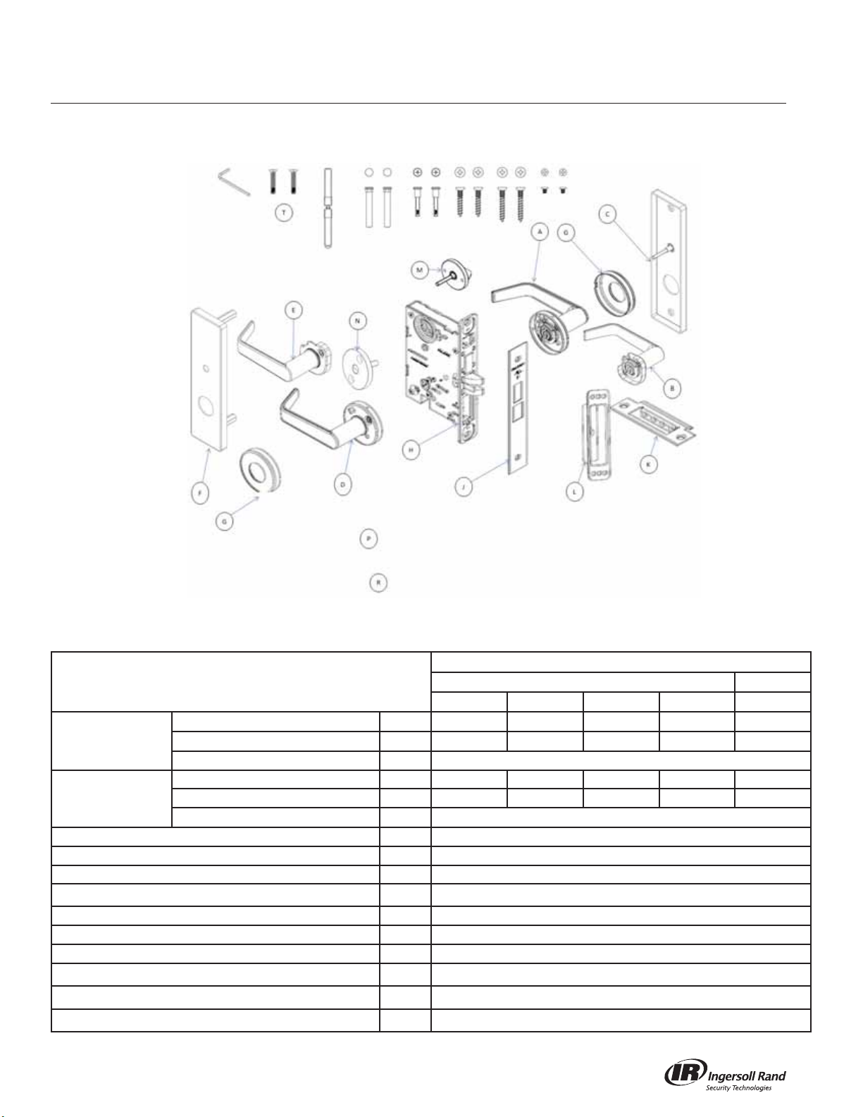
MA301 - Privacy, Bedroom/Bath
Trim
Lever Knob
Description
KNOB/LEVER SECTIONAL
INSIDE TRIM
OUTSIDE TRIM
ROSE (2 REQ'D) G S76012
ASSY, LOCK UNIT H A7802
FACEPLATE J S77819
STRIKE ASSY
STRIKE BOX L PE1396
THUMB TURN M AS76319
EMERGENCY TURN N AS76853
DOOR MARKER
INSTRUCTION SHEETS
SCREW PACK
KNOB/LEVER ESCUTCHEON
ESCUTCHEON C AE77012-IT
KNOB/LEVER SECTIONAL D AS76280 AS76526 AS76029 AS76140 AS76100
KNOB/LEVER ESCUTCHEON E AE77280 AE77526 AE77029 AE77140 AE77100
ESCUTCHEON
A
B
F
K
P
R
T
Dane Sutro Avalon Quantum Hana
AS76280 AS76526 AS76029 AS76140 AS76100
AE77280 AE77526 AE77029 AE77140 AE77100
AE77012-OT
A8737-1
Q513-068
Q513-067
See page 34
7
Page 12
MA311 - Privacy, Bedroom/Bath
MA-Series Service Manual
Trim
Lever Knob
Description
KNOB/LEVER SECTIONAL
INSIDE TRIM
OUTSIDE TRIM
ROSE (2 REQ'D) G S76012
ASSY, LOCK UNIT H A7819
FACEPLATE J S77819
STRIKE ASSY
STRIKE BOX L PE1396
THUMB TURN M AS76319
EMERGENCY TURN N AS76853
DOOR MARKER
INSCTRUCTION SHEETS
SCREW PACK
KNOB/LEVER ESCUTCHEON
ESCUTCHEON C AE77012-IT
KNOB/LEVER SECTIONAL D AS76280 AS76526 AS76029 AS76140 AS76100
KNOB/LEVER ESCUTCHEON E AE77280 AE77526 AE77029 AE77140 AE77100
ESCUTCHEON
A
B
F
K
P
R
T
Dane Sutro Avalon Quantum Hana
AS76280 AS76526 AS76029 AS76140 AS76100
AE77280 AE77526 AE77029 AE77140 AE77100
AE77012-OT
A8737-1
Q513-068
Q513-067
See page 34
8
Page 13

MA-Series Service Manual
MA321 - Privacy, Bedroom/Bath
Trim
Lever Knob
Description
KNOB/LEVER SECTIONAL
INSIDE TRIM
OUTSIDE TRIM
ROSE (2 REQ'D) G S76012
ASSY, LOCK UNIT H A7822
FACEPLATE J S77801
STRIKE ASSY
STRIKE BOX L PE1396
THUMB TURN M AS76319
EMERGENCY TURN N AS76853
DOOR MARKER
INSTRUCTION SHEETS
SCREW PACK
KNOB/LEVER ESCUTCHEON
ESCUTCHEON C AE77012-IT
KNOB/LEVER SECTIONAL D AS76280 AS76526 AS76029 AS76140 AS76100
KNOB/LEVER ESCUTCHEON E AE77280 AE77526 AE77029 AE77140 AE77100
ESCUTCHEON
A
B
F
K
P
R
T
Dane Sutro Avalon Quantum Hana
AS76280 AS76526 AS76029 AS76140 AS76100
AE77280 AE77526 AE77029 AE77140 AE77100
AE77012-OT
A8737-1
Q513-068
Q513-067
See page 34
9
Page 14
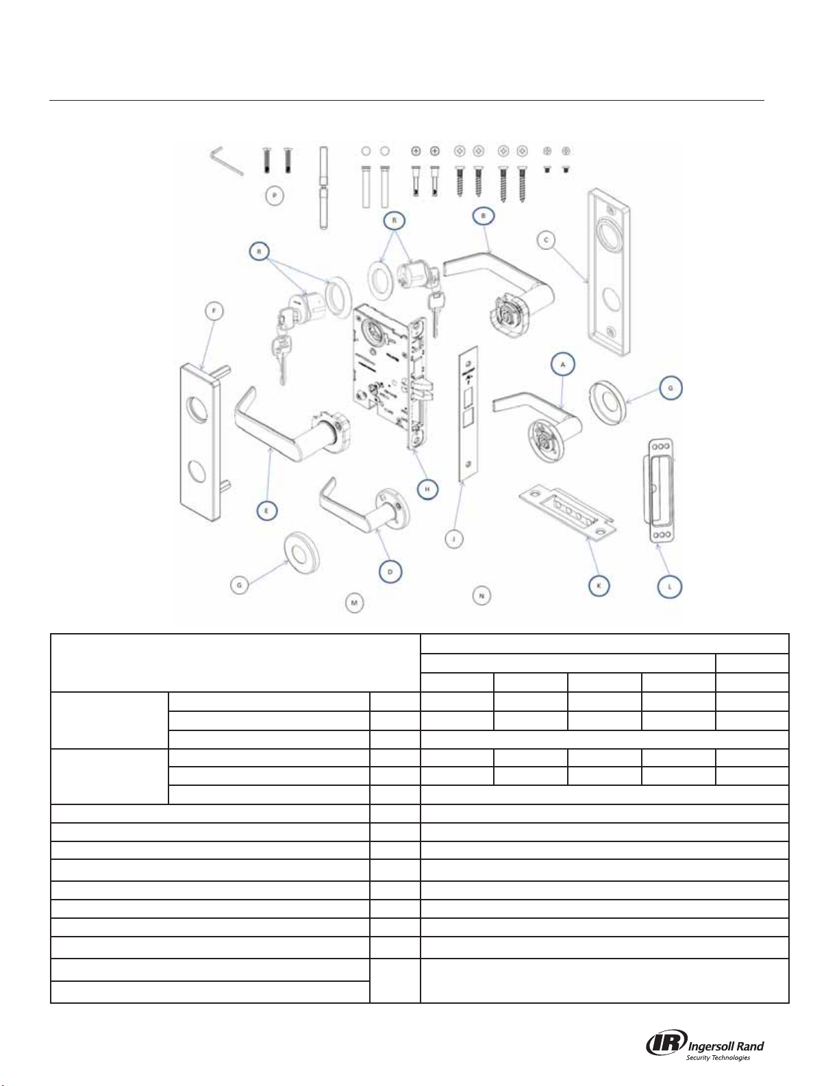
MA371 - Store Door Lock
MA-Series Service Manual
SFIC Not Shown
Trim
Lever Knob
Description
KNOB/LEVER SECTIONAL
INSIDE TRIM
OUTSIDE TRIM
ROSE (2 REQ'D) G S76012
ASSY, LOCK UNIT H A7814
FACEPLATE J S77819
STRIKE ASSY
STRIKE BOX L PE1396
DOOR MARKER M Q513-068
INSTRUCTION SHEETS N Q513-067
SCREW PACK
CYLINDER, CONVENTIONAL (2 REQ'D)
CYLINDER, SFIC (2 REQ'D)
KNOB/LEVER ESCUTCHEON
ESCUTCHEON C E77012-IC
KNOB/LEVER SECTIONAL D AS76280 AS76526 AS76029 AS76140 AS76100
KNOB/LEVER ESCUTCHEON E AE77280 AE77526 AE77029 AE77140 AE77100
ESCUTCHEON
A
B
F
K
P
R See Cylinder Chart on page 39
Dane Sutro Avalon Quantum Hana
AS76280 AS76526 AS76029 AS76140 AS76100
AE77280 AE77526 AE77029 AE77140 AE77100
AE77012-OC
A8737-1
See page 34
10
Page 15
MA-Series Service Manual
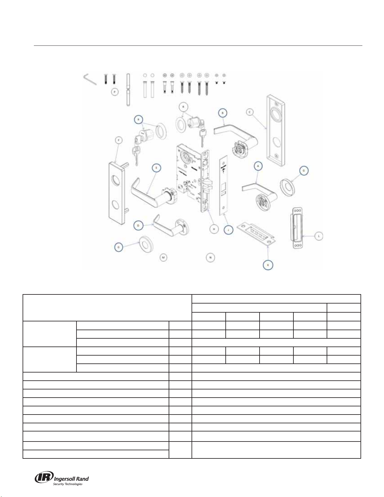
MA381 - Apartment, Exit
SFIC Not Shown
Trim
Lever Knob
Description
KNOB/LEVER SECTIONAL
INSIDE TRIM
OUTSIDE TRIM
ROSE (2 REQ'D) G S76012
ASSY, LOCK UNIT H A7809
FACEPLATE J S77805
STRIKE ASSY K A8737-1
STRIKE BOX L PE1396
DOOR MARKER M Q513-068
INSTRUCTION SHEETS N Q513-067
SCREW PACK
CYLINDER, CONVENTIONAL (2 REQ'D)
CYLINDER, SFIC (2 REQ'D)
KNOB/LEVER ESCUTCHEON
ESCUTCHEON C E77012-IC
KNOB/LEVER SECTIONAL D AS76280 AS76526 AS76029 AS76140 AS76100
KNOB/LEVER ESCUTCHEON E AE77280 AE77526 AE77029 AE77140 AE77100
ESCUTCHEON
A
B
F
P
R See Cylinder Chart on page 39
Dane Sutro Avalon Quantum Hana
AS76280 AS76526 AS76029 AS76140 AS76100
AE77280 AE77526 AE77029 AE77140 AE77100
AE77012-OC
See page 34
11
Page 16
MA411 - Asylum or Institutional Lock
MA-Series Service Manual
SFIC Not Shown
Trim
Lever Knob
Description
KNOB/LEVER SECTIONAL
INSIDE TRIM
OUTSIDE TRIM
ROSE (2 REQ'D) G S76012
ASSY, LOCK UNIT H A7830
FACEPLATE J S77805
STRIKE ASSY
STRIKE BOX L PE1396
DOOR MARKER M Q513-068
INSTRUCTION SHEETS N Q513-067
SCREW PACK
CYLINDER, CONVENTIONAL (2 REQ'D)
CYLINDER, SFIC (2 REQ'D)
KNOB/LEVER ESCUTCHEON
ESCUTCHEON C E77012-IC
KNOB/LEVER SECTIONAL D AS76280 AS76526 AS76029 AS76140 AS76100
KNOB/LEVER ESCUTCHEON E AE77280 AE77526 AE77029 AE77140 AE77100
ESCUTCHEON
A
B
F
K
P
R See Cylinder Chart on page 39
Dane Sutro Avalon Quantum Hana
AS76280 AS76526 AS76029 AS76140 AS76100
AE77280 AE77526 AE77029 AE77140 AE77100
AE77012-OC
A8737-1
See page 34
12
Page 17

MA-Series Service Manual
MA431 - Intruder Dead Bolt Lock
SFIC Not Shown
Trim
Lever Knob
Description
KNOB/LEVER SECTIONAL
INSIDE TRIM
OUTSIDE TRIM
ROSE (2 REQ'D) G S76012
ASSY, LOCK UNIT H A7813
FACEPLATE J S77819
STRIKE ASSY K A8737-1
STRIKE BOX L PE1396
DOOR MARKER N Q513-068
INSTRUCTION SHEETS P Q513-067
SCREW PACK
CYLINDER, CONVENTIONAL (2 REQ'D)
CYLINDER, SFIC (2 REQ'D)
KNOB/LEVER ESCUTCHEON
ESCUTCHEON C E77012-IC
KNOB/LEVER SECTIONAL D AS76280 AS76526 AS76029 AS76140 AS76100
KNOB/LEVER ESCUTCHEON E AE77280 AE77526 AE77029 AE77140 AE77100
ESCUTCHEON
A
B
F
R
T See Cylinder Chart on page 39
Dane Sutro Avalon Quantum Hana
AS76280 AS76526 AS76029 AS76140 AS76100
AE77280 AE77526 AE77029 AE77140 AE77100
AE77012-OC
See page 34
13
Page 18

MA441 - Intruder Latch Bolt Lock
MA-Series Service Manual
SFIC Not Shown
Trim
Lever Knob
Description
KNOB/LEVER SECTIONAL
INSIDE TRIM
OUTSIDE TRIM
ROSE (2 REQ'D) G S76012
ASSY, LOCK UNIT H A7832
FACEPLATE J S77805
STRIKE ASSY K A8737-1
STRIKE BOX L PE1396
DOOR MARKER M Q513-068
INSTRUCTION SHEETS N Q513-067
SCREW PACK
CYLINDER, CONVENTIONAL (2 REQ'D)
CYLINDER, SFIC (2 REQ'D)
KNOB/LEVER ESCUTCHEON
ESCUTCHEON C E77012-IC
KNOB/LEVER SECTIONAL D AS76280 AS76526 AS76029 AS76140 AS76100
KNOB/LEVER ESCUTCHEON E AE77280 AE77526 AE77029 AE77140 AE77100
ESCUTCHEON
A
B
F
P
R See Cylinder Chart on page 39
Dane Sutro Avalon Quantum Hana
AS76280 AS76526 AS76029 AS76140 AS76100
AE77280 AE77526 AE77029 AE77140 AE77100
AE77012-OC
See page 34
14
Page 19

MA-Series Service Manual
MA451 - Hotel Guest Lock
SFIC Not Shown
Trim
Lever Knob
Description
KNOB/LEVER SECTIONAL
INSIDE TRIM
OUTSIDE TRIM
ROSE (2 REQ'D) G S76012
ASSY, LOCK UNIT H A7815
FACEPLATE J S77815
STRIKE ASSY K A8737-1
STRIKE BOX L PE1396
THUMB TURN M AS76319
DOOR MARKER N Q513-068
INSTRUCTION SHEETS
SCREW PACK R See page 34
CYLINDER, CONVENTIONAL
CYLINDER, SFIC
KNOB/LEVER ESCUTCHEON
ESCUTCHEON C AE77012-IT
KNOB/LEVER SECTIONAL D AS76280 AS76526 AS76029 AS76140 AS76100
KNOB/LEVER ESCUTCHEON E AE77280 AE77526 AE77029 AE77140 AE77100
ESCUTCHEON
A
B
F
P
T See Cylinder Chart on page 39
Dane Sutro Avalon Quantum Hana
AS76280 AS76526 AS76029 AS76140 AS76100
AE77280 AE77526 AE77029 AE77140 AE77100
AE77012-OC
Q513-067
15
Page 20

MA521 - Entry Lock
MA-Series Service Manual
SFIC Not Shown
Trim
Lever Knob
Description
KNOB/LEVER SECTIONAL
INSIDE TRIM
OUTSIDE TRIM
ROSE (2 REQ'D) G S76012
ASSY, LOCK UNIT H A7804
FACEPLATE J S77804
STRIKE ASSY
STRIKE BOX L PE1396
DOOR MARKER M Q513-068
INSTRUCTION SHEETS N Q513-067
SCREW PACK
CYLINDER, CONVENTIONAL
CYLINDER, SFIC
KNOB/LEVER ESCUTCHEON
ESCUTCHEON C E77012-IP
KNOB/LEVER SECTIONAL D AS76280 AS76526 AS76029 AS76140 AS76100
KNOB/LEVER ESCUTCHEON E AE77280 AE77526 AE77029 AE77140 AE77100
ESCUTCHEON
A
B
F
K
P
R See Cylinder Chart on page 39
Dane Sutro Avalon Quantum Hana
AS76280 AS76526 AS76029 AS76140 AS76100
AE77280 AE77526 AE77029 AE77140 AE77100
AE77012-OC
A8737-1
See page 34
16
Page 21

MA-Series Service Manual
MA531 - Apartment Corridor Door Lock
SFIC Not Shown
Trim
Lever Knob
Description
KNOB/LEVER SECTIONAL
INSIDE TRIM
OUTSIDE TRIM
ROSE (2 REQ'D) G S76012
ASSY, LOCK UNIT H A7820
FACEPLATE J S77820
STRIKE ASSY K A8737-1
STRIKE BOX L PE1396
THUMB TURN M AS76319
DOOR MARKER N Q513-068
INSTRUCTION SHEETS
SCREW PACK R See page 34
CYLINDER, CONVENTIONAL
CYLINDER, SFIC
KNOB/LEVER ESCUTCHEON
ESCUTCHEON C AE77012-IT
KNOB/LEVER SECTIONAL D AS76280 AS76526 AS76029 AS76140 AS76100
KNOB/LEVER ESCUTCHEON E AE77280 AE77526 AE77029 AE77140 AE77100
ESCUTCHEON
A
B
F
P
T See Cylinder Chart on page 39
Dane Sutro Avalon Quantum Hana
AS76280 AS76526 AS76029 AS76140 AS76100
AE77280 AE77526 AE77029 AE77140 AE77100
AE77012-OC
Q513-067
17
Page 22

MA541 - Entry/Office Lock
MA-Series Service Manual
SFIC Not Shown
Trim
Lever Knob
Description
KNOB/LEVER SECTIONAL
INSIDE TRIM
OUTSIDE TRIM
ROSE (2 REQ'D) G S76012
ASSY, LOCK UNIT H A7821
FACEPLATE J S77819
STRIKE ASSY K A8737-1
STRIKE BOX L PE1396
THUMB TURN M AS76319
DOOR MARKER N Q513-068
INSTRUCTION SHEETS
SCREW PACK R See page 34
CYLINDER, CONVENTIONAL
CYLINDER, SFIC
KNOB/LEVER ESCUTCHEON
ESCUTCHEON C AE77012-IT
KNOB/LEVER SECTIONAL D AS76280 AS76526 AS76029 AS76140 AS76100
KNOB/LEVER ESCUTCHEON E AE77280 AE77526 AE77029 AE77140 AE77100
ESCUTCHEON
A
B
F
P
T See Cylinder Chart on page 39
Dane Sutro Avalon Quantum Hana
AS76280 AS76526 AS76029 AS76140 AS76100
AE77280 AE77526 AE77029 AE77140 AE77100
AE77012-OC
Q513-067
18
Page 23

MA-Series Service Manual
MA551 - Holdback Lock
SFIC Not Shown
Trim
Lever Knob
Description
KNOB/LEVER SECTIONAL
INSIDE TRIM
OUTSIDE TRIM
ROSE (2 REQ'D) G S76012
ASSY, LOCK UNIT H A7806
FACEPLATE J S77805-LL
STRIKE ASSY K A8737-1
STRIKE BOX L PE1396
DOOR MARKER M Q513-068
INSTRUCTION SHEETS N Q513-067
SCREW PACK R See page 34
CYLINDER, CONVENTIONAL
CYLINDER, SFIC
KNOB/LEVER ESCUTCHEON
ESCUTCHEON C E77012-IP
KNOB/LEVER SECTIONAL D AS76280 AS76526 AS76029 AS76140 AS76100
KNOB/LEVER ESCUTCHEON E AE77280 AE77526 AE77029 AE77140 AE77100
ESCUTCHEON
A
B
F
T See Cylinder Chart on page 39
Dane Sutro Avalon Quantum Hana
AS76280 AS76526 AS76029 AS76140 AS76100
AE77280 AE77526 AE77029 AE77140 AE77100
AE77012-OC
19
Page 24

MA561 - Classroom Lock
MA-Series Service Manual
SFIC Not Shown
Trim
Lever Knob
Description
KNOB/LEVER SECTIONAL
INSIDE TRIM
OUTSIDE TRIM
ROSE (2 REQ'D) G S76012
ASSY, LOCK UNIT H A7805
FACEPLATE J S77805
STRIKE ASSY
STRIKE BOX L PE1396
DOOR MARKER M Q513-068
INSTRUCTION SHEETS N Q513-067
SCREW PACK
CYLINDER, CONVENTIONAL
CYLINDER, SFIC
KNOB/LEVER ESCUTCHEON
ESCUTCHEON C E77012-IP
KNOB/LEVER SECTIONAL D AS76280 AS76526 AS76029 AS76140 AS76100
KNOB/LEVER ESCUTCHEON E AE77280 AE77526 AE77029 AE77140 AE77100
ESCUTCHEON
A
B
F
K
P
R See Cylinder Chart on page 39
Dane Sutro Avalon Quantum Hana
AS76280 AS76526 AS76029 AS76140 AS76100
AE77280 AE77526 AE77029 AE77140 AE77100
AE77012-OC
A8737-1
See page 34
20
Page 25

MA-Series Service Manual
MA571 - Dormitory or Exit Lock
SFIC Not Shown
Trim
Lever Knob
Description
KNOB/LEVER SECTIONAL
INSIDE TRIM
OUTSIDE TRIM
ROSE (2 REQ'D) G S76012
ASSY, LOCK UNIT H A7813
FACEPLATE J S77819
STRIKE ASSY K A8737-1
STRIKE BOX L PE1396
THUMB TURN M AS76319
DOOR MARKER N Q513-068
INSTRUCTION SHEETS
SCREW PACK R See page 34
CYLINDER, CONVENTIONAL
CYLINDER, SFIC
KNOB/LEVER ESCUTCHEON
ESCUTCHEON C AE77012-IT
KNOB/LEVER SECTIONAL D AS76280 AS76526 AS76029 AS76140 AS76100
KNOB/LEVER ESCUTCHEON E AE77280 AE77526 AE77029 AE77140 AE77100
ESCUTCHEON
A
B
F
P
T See Cylinder Chart on page 39
Dane Sutro Avalon Quantum Hana
AS76280 AS76526 AS76029 AS76140 AS76100
AE77280 AE77526 AE77029 AE77140 AE77100
AE77012-OC
Q513-067
21
Page 26

MA581 - Storeroom / Closet Lock
MA-Series Service Manual
SFIC Not Shown
Trim
Lever Knob
Description
KNOB/LEVER SECTIONAL
INSIDE TRIM
OUTSIDE TRIM
ROSE (2 REQ'D) G S76012
ASSY, LOCK UNIT H A7807
FACEPLATE J S77805
STRIKE ASSY K A8737-1
STRIKE BOX L PE1396
DOOR MARKER M Q513-068
INSTRUCTION SHEETS N Q513-067
SCREW PACK
CYLINDER, CONVENTIONAL
CYLINDER, SFIC
KNOB/LEVER ESCUTCHEON
ESCUTCHEON C E77012-IP
KNOB/LEVER SECTIONAL D AS76280 AS76526 AS76029 AS76140 AS76100
KNOB/LEVER ESCUTCHEON E AE77280 AE77526 AE77029 AE77140 AE77100
ESCUTCHEON
A
B
F
P
R See Cylinder Chart on page 39
Dane Sutro Avalon Quantum Hana
AS76280 AS76526 AS76029 AS76140 AS76100
AE77280 AE77526 AE77029 AE77140 AE77100
AE77012-OC
See page 34
22
Page 27

MA-Series Service Manual
MA621 - Front Door / Apartment Corridor
SFIC Not Shown
Trim
Lever Knob
Description
KNOB/LEVER SECTIONAL
INSIDE TRIM
OUTSIDE TRIM
ROSE (2 REQ'D) G S76012
ASSY, LOCK UNIT H A7808
FACEPLATE J S77811
STRIKE ASSY K A8737-1
STRIKE BOX L PE1396
THUMB TURN M AS76319
DOOR MARKER N Q513-068
INSTRUCTION SHEETS
SCREW PACK R See page 34
CYLINDER, CONVENTIONAL
CYLINDER, SFIC
KNOB/LEVER ESCUTCHEON
ESCUTCHEON C AE77012-IT
KNOB/LEVER SECTIONAL D AS76280 AS76526 AS76029 AS76140 AS76100
KNOB/LEVER ESCUTCHEON E AE77280 AE77526 AE77029 AE77140 AE77100
ESCUTCHEON
A
B
F
P
T See Cylinder Chart on page 39
Dane Sutro Avalon Quantum Hana
AS76280 AS76526 AS76029 AS76140 AS76100
AE77280 AE77526 AE77029 AE77140 AE77100
AE77012-OC
Q513-067
23
Page 28

MA641 - Dormitory Lock
MA-Series Service Manual
SFIC Not Shown
Trim
Lever Knob
Description
KNOB/LEVER SECTIONAL
INSIDE TRIM
OUTSIDE TRIM
ROSE (2 REQ'D) G S76012
ASSY, LOCK UNIT H A7815
FACEPLATE J S77815
STRIKE ASSY K A8737-1
STRIKE BOX L PE1396
THUMB TURN M AS76319
DOOR MARKER N Q513-068
INSTRUCTION SHEETS
SCREW PACK R See page 34
CYLINDER, CONVENTIONAL
CYLINDER, SFIC
KNOB/LEVER ESCUTCHEON
ESCUTCHEON C AE77012-IT
KNOB/LEVER SECTIONAL D AS76280 AS76526 AS76029 AS76140 AS76100
KNOB/LEVER ESCUTCHEON E AE77280 AE77526 AE77029 AE77140 AE77100
ESCUTCHEON
A
B
F
P
T See Cylinder Chart on page 39
Dane Sutro Avalon Quantum Hana
AS76280 AS76526 AS76029 AS76140 AS76100
AE77280 AE77526 AE77029 AE77140 AE77100
AE77012-OC
Q513-067
24
Page 29

MA-Series Service Manual
MA851 - Electrified EL - 12 & 24 VDC (Fail Safe)
SFIC Not Shown
Trim
Lever Knob
Description
KNOB/LEVER SECTIONAL
INSIDE TRIM
OUTSIDE TRIM
ROSE (2 REQ'D) G S76012
ASSY, LOCK UNIT H A7851
FACEPLATE J S77805
STRIKE ASSY K A8737-1
STRIKE BOX L PE1396
DOOR MARKER M Q513-068
INSTRUCTION SHEETS N Q513-067
SCREW PACK
CYLINDER, CONVENTIONAL
CYLINDER, SFIC
KNOB/LEVER ESCUTCHEON
ESCUTCHEON C E77012-IP
KNOB/LEVER SECTIONAL D AS76280 AS76526 AS76029 AS76140 AS76100
KNOB/LEVER ESCUTCHEON E AE77280 AE77526 AE77029 AE77140 AE77100
ESCUTCHEON
A
B
F
P
R See Cylinder Chart on page 39
Dane Sutro Avalon Quantum Hana
AS76280 AS76526 AS76029 AS76140 AS76100
AE77280 AE77526 AE77029 AE77140 AE77100
AE77012-OC
See page 34
25
Page 30

MA-Series Service Manual
MA881 - Electrified EU - 12 & 24 VDC (Fail Secure)
SFIC Not Shown
Trim
Lever Knob
Description
KNOB/LEVER SECTIONAL A AS76280 AS76526 AS76029 AS76140 AS76100
INSIDE TRIM
OUTSIDE TRIM
ROSE (2 REQ'D) G S76012
ASSY, LOCK UNIT H A7881
FACEPLATE J S77805
STRIKE ASSY K A8737-1
STRIKE BOX L PE1396
DOOR MARKER M Q513-068
INSTRUCTION SHEETS N Q513-067
SCREW PACK
CYLINDER, CONVENTIONAL
CYLINDER, SFIC
KNOB/LEVER ESCUTCHEON
ESCUTCHEON C E77012-IP
KNOB/LEVER SECTIONAL D AS76280 AS76526 AS76029 AS76140 AS76100
KNOB/LEVER ESCUTCHEON E AE77280 AE77526 AE77029 AE77140 AE77100
ESCUTCHEON
B
F
P
R See Cylinder Chart on page 39
Dane Sutro Avalon Quantum Hana
AE77280 AE77526 AE77029 AE77140 AE77100
AE77012-OC
See page 34
26
Page 31

MA-Series Service Manual
MA911 - Classroom Dead Lock
SFIC Not Shown
Trim
Lever Knob
Description
KNOB/LEVER SECTIONAL
INSIDE TRIM
OUTSIDE TRIM
ASSY, LOCK UNIT C A7829
FACEPLATE D S77816
STRIKE ASSY E A8737-1
STRIKE BOX
THUMB TURN G AS76319
DOOR MARKER H Q513-068
INSTRUCTION SHEETS J Q513-067
SCREW PACK
CYLINDER, CONVENTIONAL
CYLINDER, SFIC
KNOB/LEVER ESCUTCHEON
ESCUTCHEON A AE77012-IE
KNOB/LEVER SECTIONAL - N/R N/R N/R N/R N/R
KNOB/LEVER ESCUTCHEON - N/R N/R N/R N/R N/R
ESCUTCHEON
-
-
B
F
K
L See Cylinder Char t on page 39
Dane Sutro Avalon Quantum Hana
N/R N/R N/R N/R N/R
N/R N/R N/R N/R N/R
AE77012-OK
PE1396
See page 34
27
Page 32

MA921 - Dead Lock
MA-Series Service Manual
Trim
Lever Knob
Description
KNOB/LEVER SECTIONAL
INSIDE TRIM
OUTSIDE TRIM
ASSY, LOCK UNIT C A7816
FACEPLATE D S77816
STRIKE ASSY E A8737-1
STRIKE BOX
DOOR MARKER G Q513-068
INSTRUCTION SHEETS H Q513-067
SCREW PACK J See page 34
CYLINDER, CONVENTIONAL
CYLINDER, SFIC
KNOB/LEVER ESCUTCHEON
ESCUTCHEON A E77012-IB
KNOB/LEVER SECTIONAL - N/R N/R N/R N/R N/R
KNOB/LEVER ESCUTCHEON - N/R N/R N/R N/R N/R
ESCUTCHEON
-
-
B
F
K See Cylinder Chart on page 39
Dane Sutro Avalon Quantum Hana
N/R N/R N/R N/R N/R
N/R N/R N/R N/R N/R
AE77012-OK
PE1396
28
Page 33

MA-Series Service Manual
MA931 - Dead Lock
SFIC Not Shown
Trim
Lever Knob
Description
KNOB/LEVER SECTIONAL
INSIDE TRIM
OUTSIDE TRIM
ASSY, LOCK UNIT C A7816
FACEPLATE D S77816
STRIKE ASSY E A8737-1
STRIKE BOX
DOOR MARKER G Q513-068
INSTRUCTION SHEETS H Q513-067
SCREW PACK J See page 34
CYLINDER, CONVENTIONAL (2 REQ'D)
CYLINDER, SFIC (2 REQ'D)
KNOB/LEVER ESCUTCHEON
ESCUTCHEON A E77012-IK
KNOB/LEVER SECTIONAL - N/R N/R N/R N/R N/R
KNOB/LEVER ESCUTCHEON - N/R N/R N/R N/R N/R
ESCUTCHEON
-
-
B
F
K See Cylinder Chart on page 39
Dane Sutro Avalon Quantum Hana
N/R N/R N/R N/R N/R
N/R N/R N/R N/R N/R
AE77012-OK
PE1396
29
Page 34

MA941 - Dead Lock
MA-Series Service Manual
SFIC Not Shown
Trim
Lever Knob
Description
KNOB/LEVER SECTIONAL
INSIDE TRIM
OUTSIDE TRIM
ASSY, LOCK UNIT C A7816
FACEPLATE D S77816
STRIKE ASSY E A8737-1
STRIKE BOX
THUMBTURN G AS76319
DOOR MARKER H Q513-068
INSTRUCTION SHEETS J Q513-067
SCREW PACK K See page 34
CYLINDER, CONVENTIONAL (2 REQ'D)
CYLINDER, SFIC (2 REQ'D)
KNOB/LEVER ESCUTCHEON
ESCUTCHEON A AE77012-IE
KNOB/LEVER SECTIONAL - N/R N/R N/R N/R N/R
KNOB/LEVER ESCUTCHEON - N/R N/R N/R N/R N/R
ESCUTCHEON
-
-
B
F
L See Cylinder Char t on page 39
Dane Sutro Avalon Quantum Hana
N/R N/R N/R N/R N/R
N/R N/R N/R N/R N/R
AE77012-OK
PE1396
30
Page 35

MA-Series Service Manual
MA12 - Single Dummy
Knob/Lever on One Side Fixed
Description Dane Sutro Avalon Quantum Hana
KNOB/LEVER SECTIONAL
TRIM
ROSE D S76012
DOOR MARKER
SCREW PACK
TORX SCREW PACK (OPTIONAL) E77308
INSTRUCTION SHEET G Q513-067
KNOB/LEVER ESCUTCHEON
ESCUTCHEON C E77012-IP
A
B
E
F
AS76280-D AS76526-D AS76029-D AS76140-D AS76100-D
AE77280-D AE77526-D AE77029-D AE77140-D AE77100-D
Trim
Lever Knob
Q513-068
E77331
31
Page 36

MA18 - Double Dummy
MA-Series Service Manual
Knob/Lever on Both Sides Fixed
Description Dane Sutro Avalon Quantum Hana
KNOB/LEVER SECTIONAL
INSIDE TRIM
OUTSIDE TRIM
ROSE (2 REQ'D) G S76012
DOOR MARKER H Q513-068
INSTRUCTION SHEETS J Q513-067
SCREW PACK K See page 34
KNOB/LEVER ESCUTCHEON
ESCUTCHEON C E77012-IP
KNOB/LEVER SECTIONAL D AS76280-D AS76526-D AS76029-D AS76140-D AS76100-D
KNOB/LEVER ESCUTCHEON E AE77280-D AE77526-D AE77029-D AE77140-D AE77100-D
ESCUTCHEON
AS76280-D AS76526-D AS76029-D AS76140-D AS76100-D
A
AE77280-D AE77526-D AE77029-D AE77140-D AE77100-D
B
F
Trim
Lever Knob
AE77012-0P
32
Page 37

MA-Series Service Manual
Levers
Knob and Lever Designs
Gala
Napa
AG (Avalon-Gala) DG (Dane-Gala)
QG (Quantum-Gala) SG (Sutro-Gala)
AN (Avalon-Napa) DN (Dane-Napa)
Knobs
HG (Hana-Gala)
QN (Quantum-Napa) SN (Sutro-Napa)
HN (Hana-Napa)
33
Page 38

Screw Packs
MA-Series Screw Packs
Part
Number
S76300
S76301
S76302
S76303
S76306
S76307
S76331
#8-32 x ¹⁄₄” L Machine Screw
#12-12/ #12-24 x 1¹⁄₂” L Wood/machine Combination Screw
#12-12/ #12-24 x 1¹⁄₄” L Wood/machine Combination Screw
#8-32 x 1¹⁄₄” L Mounting Screw
ø ¹⁄₄” x 1¹¹⁄₁₆” L Post
⁵⁄₁₆” x 1⁹⁄₁₆” L x 2 pcs STD Sindle Assembly
³⁄₃₂” Allen Wrench
#8-32 x ¹⁄₄” L Machine Screw
#12-12/ #12-24 x 1¹⁄₂” L Wood/machine Combination Screw
#12-12/ #12-24 x 1¹⁄₄” L Wood/machine Combination Screw
#8-32 x 1¹⁄₂” L Mounting Screw
ø ¹⁄₄” x 2¹⁄₄” L Post
⁵⁄₁₆” x 1⁷⁄₈” L x 2 pcs EXT Sindle Assembly
³⁄₃₂” Allen Wrench
#8-32 x ¹⁄₄” L Machine Screw
#12-12/ #12-24 x 1¹⁄₂” L Wood/machine Combination Screw
#12-12/ #12-24 x 1¹⁄₄” L Wood/machine Combination Screw
#8-32 x 1¹⁄₄” L Mounting Screw
ø ¹⁄₄” x 1¹¹⁄₁₆” L Post
⁵⁄₁₆” x 1¹⁄₄” L x 2 pcs STD Sindle Assembly
³⁄₃₂” Allen Wrench
#8-32 x ¹⁄₄” L Machine Screw
#12-12/ #12-24 x 1¹⁄₂” L Wood/machine Combination Screw
#12-12/ #12-24 x 1¹⁄₄” L Wood/machine Combination Screw
#8-32 x 1¹⁄₂” L Mounting Screw
ø ¹⁄₄” x 2¹⁄₄” L Post
⁵⁄₁₆” x 1⁹⁄₁₆” L x 2 pcs EXT Sindle Assembly
³⁄₃₂” Allen Wrench
#8-32 x ¹⁄₄” L Torx Head Machine Screw
#12-12/ #12-24 x 1¹⁄₂” L Torx Head Wood/machine Combination Screw
#8-32 x ¹⁄₄” L Torx Head Machine Screw
#12-12/ #12-24 x 1¹⁄₂” L Torx Head Wood/machine Combination Screw
#6 x ¹⁄₂” Torx Head Sheet Metal Screw
#8-32 x ¹⁄₄” L Machine Screw
#12-12/ #12-24 x 1¹⁄₂” L Wood/machine Combination Screw
#12-12/ #12-24 x 1¹⁄₄” L Wood/machine Combination Screw
#8-32 x 1¹⁄₄” L Mounting Screw
⁵⁄₁₆” x 1⁹⁄₁₆” L STD Spindle
ø 0.027” Wire, OD; ø ⁵⁄₁₆” x 1³⁄₈” L Spring
³⁄₃₂” Allen Wrench
Description Use
MA-Series Service Manual
Specify
Finish
1³⁄₈”-1⁷⁄₈” door thickness, sectional trim with
levers
Over 1⁷⁄₈”-2¹⁄₂” door thickness, sectional trim
with levers
1³⁄₈”-1⁷⁄₈” door thickness, sectional trim with
knobs
Over 1⁷⁄₈”-2¹⁄₂” door thickness, sectional trim
with knobs
Torx screw pack, sectional trim, no turn
Torx screw pack, sectional trim, with turn
Single Dummy Screw Pack
•
•
•
•
•
•
•
34
Page 39

MA-Series Service Manual
Screw Packs
Part
Number
E77300
E77301
E77302
E77303
E77306
E77307
E77308
Description Use
#8-32 x ¹⁄₄” L Machine Screw
#12-12/ #12-24 x 1¹⁄₂” Wood/machine Combination Screw
#12-12/ #12-24 x 1¹⁄₄” L Wood/machine Combination Screw
#8-32 x 1¹⁄₄” L Mounting Screw
ø ¹⁄₄” x 1¹¹⁄₁₆” L Post
⁵⁄₁₆” x 1⁹⁄₁₆” L x 2 pcs STD Sindle Assembly
#10-24 x 1¹⁄₄” Machine Screw
³⁄₃₂” Allen Wrench
#8-32 x ¹⁄₄” L Machine Screw
#12-12/ #12-24 x 1¹⁄₂” L Wood/machine Combination Screw
#12-12/ #12-24 x 1¹⁄₄” L Wood/machine Combination Screw
#8-32 x 1¹⁄₂” L Mounting Screw
ø ¹⁄₄” x 2¹⁄₄” L Post
⁵⁄₁₆” x 1⁷⁄₈” L x 2 pcs EXT Sindle Assembly
#10-24 x 2” Machine Screw
³⁄₃₂” Allen Wrench
#8-32 x ¹⁄₄” L Machine Screw
#12-12/#12-24 x 1¹⁄₂” L Wood/machine Combination Screw
#12-12/#12-24 x 1¹⁄₄” L Wood/machine Combination Screw
#8-32 x 1¹⁄₄” L Mounting Screw
ø ¹⁄₄” x 1¹¹⁄₁₆” L Post
⁵⁄₁₆” x 1¹⁄₄” L x 2 pcs STD Knob Spindle Assembly
#10-24 x 1¹⁄₄ L Machine Screw
³⁄₃₂” Allen Wrench
#8-32 x ¹⁄₄” L Machine Screw
#12-12/#12-24 x 1¹⁄₂” L Wood/machine Combination Screw
#12-12/#12-24 x 1¹⁄₄” L Wood/machine Combination Screw
#8-32 x 1¹⁄₂” L Trim Screw
ø ¹⁄₄” x 1¹¹⁄₁₆” L Post
⁵⁄₁₆” x 1⁹⁄₁₆” L x 2 pcs EXT Spindle Assembly
#10-24 x 2” L Machine Screw
³⁄₃₂” Allen Wrench
#8-32 x ¹⁄₄” L Torx Head Machine Screw
#12-12/#12-24 x 1¹⁄₂” L Torx Head Wood/machine Combination Screw
#10-24 x 1¹⁄₄ L Torx Head, Machine Screw
#8-32 x ¹⁄₄” L Torx Head Machine Screw
#12-12/#12-24 x 1¹⁄₂” L Torx Head Wood/machine Combination Screw
#10-24 x 2” L Torx Head Machine Screw
#8-32 x ¹⁄₄” L Torx Head Machine Screw
#12-12/#12-24 x 1¹⁄₂” L Torx Head Wood/machine Screw
#10-24/#10 x 1¹⁄₄” L Torx Head Wood/machine Screw
1³⁄₈”-1⁷⁄₈” door thickness, escutcheon trim with
levers
Over 1⁷⁄₈”-2¹⁄₂” door thickness, escutcheon trim
with levers
1³⁄₈”-1⁷⁄₈” door thickness, escutcheon trim with
knobs
Over 1⁷⁄₈”-2¹⁄₂” door thickness, escutcheon trim
with knobs
Torx screw pack, escutcheon trim, standard
door thickness*
Torx screw pack, escutcheon trim, extended
door thickness**
Torx screw pack, rose escutcheon connection
door
Specify
Finish
•
•
•
•
•
•
•
35
Page 40

Screw Packs/Strikes
MA-Series Service Manual
Part
Number
#8-32 x ¹⁄₄” LMachine Screw
#12-12/#12-24 x 1¹⁄₂” L Wood/machine Combination Screw
#12-12/#12-24 x 1¹⁄₄” L Wood/machine Combination Screw
E77331
#8-32 x 1¹⁄₄” L Mounting Screw
⁵⁄₁₆” x 1⁹⁄₁₆” L STD Spindle
#10-24/#10 x 1¹⁄₄” L Wood/machine Combination Screw
ø 0.027 Wire, ø ⁵⁄₁₆” O.D. x 1³⁄₈” L Spring
³⁄₃₂” Allen Wrench
* 1³⁄₈”-1⁷⁄₈” Thick
** Over 1⁷⁄₈”-2¹⁄₂” Thick
Available in finishes 606, 613, 630
Non torx screw packs contain armor front screws, strike screws, trim screws, mortise screws, spindle, mounting posts
Torx screw packs contain armor front, strike, and trim screws only
Description Use
Screw pack, escutcheon connecting door
Specify
Finish
•
Strikes
Strike Lip Length (x) Lip
A8737-1
A8737-2
A8737-3
A8737-4
A8737-5
1¹⁄₄”
1⁷⁄₁₆”
1⁹⁄₁₆”
1¹¹⁄₁₆”
⁷⁄₈”
Curved Lip
Curved Lip
Curved Lip
Curved Lip
Straight Lip
Lip
Length
(x)
36
Page 41

MA-Series Service Manual
Cams
Cams
CAMs for Falcon Cylinders
The Falcon MA Series requires a different CAM for keyed functions than its predecessor, the Falcon M Series. For all keyed
functions except the MA381 function, the MA Series uses a single CAM for all standard mortise cylinders and a single CAM for all
interchangeable core mortise cylinders. The chart below lists the CAM required.
Door
Handing
ALL 5622-STD (F1)
ALL 5622-IC (F2)
The new Falcon MA Series MA381 function uses unique CAMs to operate
the lock. Different CAMs are required, depending on the handing of the lock.
The charts on the next page indicate which CAMs are to be used for each
configuration.
CAM Part
Number Outside Inside For Cylinder
MA371, MA411, MA431,
MA441, MA451, MA521,
MA531, MA541, MA551,
MA561, MA571, MA581,
MA621, MA641, MA851,
MA881, MA911, MA921,
MA931, MA941
MA371, MA411, MA431,
MA441, MA451, MA521,
MA531, MA541, MA551,
MA561, MA571, MA581,
MA621, MA641, MA851,
MA881, MA911, MA921,
MA931, MA941
MA371, MA411, MA431,
MA371, MA411, MA431,
MA441, MA931
MA441, MA931
STANDARD CYLINDER
INTERCHANGEABLE
CORE
5622 5622-IC
37
Page 42

Cams
MA-Series Service Manual
Falcon MA381 Cylinder CAM
Falcon MA381 Cylinder CAM
Configuration Chart
Door Hand Inside Cyl. Cam Outside Cyl. Cam Door Hand Inside Cyl. Cam Outside Cyl. Cam
RH/RHR 5620-STD (R3) 5621-STD (R4) RH/RHR 5620-IC (R3) 5621-IC (R4)
LH/LHR 5620-STD (L3) 5621-STD (L4) LH/LHR 5620-IC (L3) 5621-IC (L4)
Configuration Chart (Interchangeable
Core)
Inside (L3)
Inside (R3)
LH/LHR
RH/RHR
Outside (L4)
Outside (R4)
Inside (L3)
Inside (R3)
LH/LHR IC
Outside (L4)
RH/RHR IC
Outside (R4)
Complete cylinders can also be ordered for the MA381 function that will include the correct CAM (the door hand must be specified when
ordering cylinders for the MA381).
CAMs for Schlage Cylinders
The Schlage Classic cylinders (C, E, and CE keyways) will also operate the Falcon MA Series locks using the 5622-STD CAM.
38
Page 43

MA-Series Service Manual
Mortise, Rim and Cam Lock for Standard Cylinders
Mortise Cylinders
Note: Specify finish: 605,
606, 613, 625, 626, 630
Note: Specify finish: 605,
606, 613, 625, 626, 630
Mortise Cylinder
Cylinders are furnished with
#5622 cam unless otherwise
specified.
See table for product numbers.
See page 37 for optional cams
and 41 for collars.
Thumbturn Cylinder
Furnished with #5622 cam
unless otherwise specified.
See table for product numbers.
See page 37 for optional cams and
41 for collars.
Dummy Cylinder
Used to plug hole in door
where lock remains but cylinder
operation is no longer needed.
984 D 1”
985 D 1-1/8”
Keyed Mortise Cylinders
Catalog
Number
Length Pins Application
985 1-1/8” 5 or 6 Generic
986 1-1/4” 5 or 6 Generic
987 1-3/8” 6 or 7 Generic
988 1-1/2” 6 or 7 Generic
990 1-3/4” 6 or 7 Generic
992 2” 6 or 7 Generic
250 1-1/8” 6 M451 hotel function
251 1-1/4” 6 M451 hotel function
252 1-3/8” 6 M451 hotel function
253 1-3/8” 7 M451 hotel function
Thumbturn Mortise Cylinders
Catalog
Number
Length Pins Application
985T 1-1/8” - Generic
986T 1-1/4” - Generic
973 1-1/8” - M911 Classroom
Thumbturn, RH (CCW)
974 1-1/8” - M911 Classroom
thumbturn, LH (CW)
Note: Specify finish: 605,
606, 613, 625, 626, 630
39
Page 44

Mortise Cylinders
MA-Series Service Manual
Cylinder Collars
Standard Collars for Cylinders Ordered Separately
Length Cylinder Non-AR Cams AR Cam
1” 984D A08794-000 1-1/8” 250, 965, 966, 973, 974, 985 Series A08794-000 008876-002
1-1/4” 251, 986 Series A08794-001 008876-003
1-3/8” 252, 253, 987, C987, C997 A08794-002 008876-004
Longer C260 Series, (C)988, (C)990, (C)992 A08794-000 008876-000
Escutcheon Trim Rings
Door
Thickness
1-1/2” Single cylinder - A08790-000 A08790-001 A08790-002
1-1/2” Double cylinder A08790-000 - - 1-3/4” Single cylinder - - A08790-000 A08790-001
1-3/4” Double cylinder - A08790-000 A08790-001 A08790-002
2” Single cylinder - - A08790-000 A08790-001
2” Double cylinder - - A08790-000 A08790-001
2-1/4” Single cylinder - - - A08790-000
2-1/4” Double cylinder - - - 2-1/2” Single cylinder - - - 2-1/2” Double cylinder - - - -
Function
985
1-1/8”
986
1-1/4”
(C)987
1-3/8”
(C)988
1-1/2”
Sectional Trim Rings
Door
Thickness
1-1/2” Single cylinder A08794-001 A08794-002 - 1-1/2” Double cylinder A08794-002 A08794-003 - 1-3/4” Single cylinder A08794-000 A08794-001 - 1-3/4” Double cylinder A08794-001 A08794-002 A08794-002 -
2” Single cylinder - A08794-000 A08794-001 A08794-002
2” Double cylinder A08794-000 A08794-001 A08794-002 A08794-003
2-1/4” Single cylinder - - A08794-000 A08794-001
2-1/4” Double cylinder - A08794-000 A08794-001 A08794-002
2-1/2” Single cylinder - - - A08794-000
2-1/2” Double cylinder - - A08794-000 A08794-001
Function
985
1-1/8”
986
1-1/4”
(C)987
1-3/8”
(C)988
1-1/2”
40
Specify part number and finish when ordering.
(e.g. A08790-000-626)
Page 45

MA-Series Service Manual
Trim Rings & Collars
Dim. A Dim. B Part No.
3/32” 9/32” A08790-000
7/32” 13/32” A08790-001
11/32” 17/32” A08790-002
A
B
15/32” 21/32” A08790-003
43/64” 55/64” A08790-004
3/32” 9/32” A08794-000
7/32” 13/32” A08794-001
A
11/32” 17/32” A08794-002
B
15/32” 21/32” A08794-003
1/8” - 008876-000
3/16” - 008876-005
1/4” - 008876-001
3/8” - 008876-002
A
1/2” - 008876-003
5/8” - 008876-004
Mortise Cylinders
Wave washer included.
To order separately,
specify 008789-001-60.
008862-000
For all rim cylinders and cam locks.
Note: Specify finishes: 605, 606, 612, 613, 625, 626
Specify part number and finish when ordering.
(e.g. A08790-000-626)
41
Page 46

Electrical Locks
MA-Series Service Manual
Electrically Locking
MA851 Electrically Locked (Fail Safe):
Outside trim is continuously locked electrically. The latchbolt is retracted by a key outside or by the knob/lever inside.
Switch or power failure allows the outside knob/lever to retract the latchbolt. The auxiliary latch deadlocks the latchbolt
when the door is closed. The inside knob/lever is always free for immediate exit.
MA881 Electrically Unlocked (Fail Secure):
Outside trim is unlocked electrically. During switch or power failure, the latchbolt is retracted by a key outside or by
knob/lever inside. The auxiliary latch deadlocks the latchbolt when the door is closed. The inside knob/lever is always
free for immediate exit.
Electrical Requirements:
Voltage: 12V DC +/- 10%
Operating Temperature: Max +151° F, Min. -31° F
Operating Current: .42 Amps
Holding Current: .135 Amps
Voltage: 24V DC +/- 10%
Operating Temperature: Max +151° F, Min. -31° F
Operating Current: .21 Amps
Holding Current: .135 Amps
Typical Installation:
All installations should be in accordance with local electrical codes and National Electrical Code NFPA #70. It is
recommended that each lock have its own 12 or 24 volt transformer. Be sure to select the proper transformer for the
lock. Two or more locks may be operated in parallel from a single transformer provided it has the necessary current
rating. DO NOT connect locks in series from a higher voltage rated transformer. Damage to locks may occur if they
connect to a supply circuit that also contains electromagnetic devices. The transient voltage must be suppressed at
the equipment producing them before connecting the locks to a circuit. A varistor rate at 35 volts (at peak current) may
be used for transient voltage protection.
Solenoid
Operated
Lock
Rectifier (Not Furnished)
Install
varistor
here
if used
(not furnished)
Switch
(not furnished)
Door Connector
(not furnished)
Transformer
(not furnished)
12 or 24V AC 110V AC
42
Page 47

MA-Series Service Manual
Ordering Procedures
How to Order
For correct ordering, and to ensure no delays in shipment of
your order, the following descriptive data must be listed in the
sequence shown. Necessary information can be found in other
parts of this manual. The example below shows an order for 16
each MA locksets in the 521 Entry function, DG (Dane-Gala) trim
design in a 626 (satin chrome) finish, 8 RH (right hand) and 8
LH (left hand) to accommodate doors 1³⁄₄” thick with AA1-AA16
keying.
Quantity: Indicate the quantity required.
Catalog Number: Select catalog number.
Trim Design: Indicate letter of knob or lever design followed by
letter of rose or escutcheon design.
Example: DG-D for Dane lever followed by G for Gala rose.
Finish: When the finish is the same for the outside and inside
trim, it is shown once (626). For split finishes, the outside is
designated first, then the inside (626 x 625).
Latch: Two-piece mechanical anti-friction standard. All catalog
How to Order Example
Catalog
Qty.
Number
8 MA521P DG 626 STD STD 6-PIN X AA1-AA8 1-3/4” DR
8 MA521P DG 626 STD STD 6-PIN X AA9-AA16 1-3/4” DR
Trim
Design
Finish Latch Strike Cylinder RH LH RHR LHR Detail
numbers shown in this manual indicated 2³⁄₄” backset.
Strike: 4⁷⁄₈” x 1¹⁄₄” x 1¹⁄₄” lip-to-center with curved lip standard.
Optional strikes with shorter or longer lip lengths available.
Cylinder Type: For 6-Pin, add 6-Pin. For 7-Pin, add 7-Pin.
Door Hand: See chart.
Keying Detail: We suggest using the standard terms developed
by the A.H.C. (Consult Factory).
Example: AA1 - Grand Master keyed, Master keyed, change key 1.
Interchangeable Core: To order product capable of accepting
an interchangeable core, add “B” less SFIC (for interchangeable
core). To order product with an interchangeable core, add “SFIC”
(with interchangeable core). Ex: “G” with Falcon SFIC core.
Keyway: “G” is standard on regular cylinders, “A” is standard on
interchangeable cores. Other keyways available. See price book.
Additional Keys: Note the total number of keys required.
Large Bow Keys: Add - “with large bow keys”.
Door Hand
Finishes
Falcon offers several finish choices to compliment the
design elements of most any project. Falcon applies the
best available protective plating or coating to the surface of
our products to minimize the exposure to weather, pollution,
perspiration, extremes of climate, frequency of us and other
Trim Finishes Chart
Description ANSI No. Available on
Bright Brass 605 US 3 All Trim
Satin Brass 606 US 4 All Trim
Satin Bronze Oil
Rubbed
Bright Chrome 625 US 26 All Trim
Satin Chrome 626 US 26D All Trim
Satin Stainless Steel 630 US 32D All Trim
613 US 10B All Trim
factors. Please consult with us if your building is subjected to
chemical or corrosive conditions, as some finishes would not
be recommended for these areas. Falcon recommends chrome
plated or stainless steel finishes for high corrosive environments.
How to Determine the Hand of a Door
43
Page 48

Installation Instructions
Q513-067
MA-Series Service Manual
Instrucciones de instalación
Installation Instructions
Falcon MA-Lock
*For MA12, MA18, and MA161 Function Installation, See Last Page
*Para obtener información sobre la instalación de las funciones
MA12, MA18 y MA161, vea la última página
*Pour l'installation des options MA12, MA18 et MA161, consultez la dernière page
Notice d'installation
1 2
Install Lockcase
Instale la caja de la cerradura
Installez le mécanisme de serrure
Fully Tighten in Step 8
Realice los ajustes completos en el paso 8
!
Serrez fermement à l'étape 8
Install Spindles and Screw Together
Instale los husillos y el tornillo juntos
Fixez ensemble les axes de poignée et la vis
INSIDE
Interior
Intérieur
Spindle with Screw MUST be Inside!
¡El husillo con el tornillo DEBE
estar en el interior!
L'axe de poignée et la vis
DOIVENT être à l'intérieur!
Page 49

MA-Series Service Manual
Installation Instructions
3
Install Lever Posts and Screws
Instale los postes de la palanca y los tornillos
Installer les tiges de levier et les vis
Mounting Posts Must Be Installed On Outside Lever!
¡Los postes de montaje se deben instalar fuera de la palanca!
!
Les tiges de montage doivent être installées
à l'extérieur du levier!
4
Install Lever Assemblies
Instale los ensamblados de la palanca
Installez les assemblages de levier
6
Identify Trim and Install
Identifique el ribete e instálelo
Identifiez la garniture et installez
Escutcheon with Thumbturn
Escudo con tuerca mariposa
Écusson et barrette tournante
INSIDE
Interior
Intérieur
Escutcheon
Escudo
Écusson
a
b
c
a
b
c
INSIDE
Interior
INSIDE
Interior
Intérieur
5
INSIDE
Interior
Intérieur
Rose
Rosetón
Rosette
Intérieur
INSIDE
Interior
Intérieur
a
b
c
45
Page 50

Installation Instructions
MA-Series Service Manual
7
Identify Trim and Secure to Door
Identifique el ribete y asegúrelo en la puerta
Identifiez la garniture et fixez à la porte
Escutcheon with Thumbturn
Escudo con tuerca mariposa
Écusson et barrette tournante
INSIDE
Interior
Intérieur
Escutcheon
Escudo
Écusson
8
If Included, Install Cylinder
Si el cilindro está incluido, instálelo
Installez le cylindre, si inclus
INSIDE
Interior
Intérieur
!
Cylinder and Mortise Retaining Screws MUST Be Fully Tightened!
¡El cilindro y los tornillos retenedores de la cerradura de muescas
DEBEN estar bien ajustados!
Les vis de fixation du cylindre et de la mortaise
DOIVENT être serrées fermement!
INSIDE
Interior
Intérieur
Rose with Thumbturn
Coloque el rosetón con la tuerca mariposa
Rosette et barrette tournante
INSIDE
Interior
Intérieur
9
Install Armor Front
Instale el frente del blindaje
Installez la plaque de blindage
INSIDE
Interior
Intérieur
46
Page 51

MA-Series Service Manual
Installation Instructions
Mortise Rehanding (If Required)
Remanipulación de la cerradura de muescas (si se requiere)
Déplacement de la mortaise (si nécessaire)
a. Remove Screw
a. Quite el tornillo
a. Retirez la vis
b. Remove Latch Bolt and Rotate 180˚
b. Quite el perno del pestillo y gírelo 180°
b. Retirez le pêne demi-tour et tourner à 180°
d. Move Handing Screws to Opposite Side
d. Mueva los tornillos de manejo al lado opuesto
d. Déplacer les vis de réglage du côté opposé
Note: Handing Screws to be Located on Non-Locking Side
Nota: Los tornillos de manejo se deben ubicar
en el lado que no tiene la cerradura
Remarque : Les vis de réglage doivent figurer au côté sans verrouillage
MA551 Holdback Lock Handing
Manejo de la cerradura de retención MA551
Verrou de réglage de retenue MA551
180˚
Note: Piece Must Sit Below Face Plate
Nota: La pieza debe ubicarse debajo
de la placa frontal
Note: La pièce doit siéger en-dessous
du plateau de montage
c. Reinstall Latch Bolt and Screw
c. Vuelva a instalar el perno y el tornillo del pestillo
c. Installez le pêne demi-tour et la vis
Retractor Spring
(TS 5754)
1) Remove Cover (Not Shown)
2) Remove Retractor Spring
3) Reverse the Order of Hub and Locking Hub
4) Replace the Retractor Spring and Cover
5) Change Direction of Latchbolt Head if Necessary
1) Quite la cubierta TS 7812-FAL (no se muestra)
2) Quite el resorte de retracción TS 5754
3) Invierta el orden de los cubos TS 7876 y TS 6854
4) Reemplace el resorte de retracción TS 5754 y la cubierta TS 7812-FAL
5) Si es necesario, cambie la dirección del cabezal del pestillo de resorte
1) Enlevez le couvercle TS 7812-FAL (non illustré)
2) Enlevez le ressort de retrait TS 5754
3) Inversez l'ordre des moyeux TS 7876 et TS 6854
4) Remplacez le ressort de retrait TS 5754 et le couvercle TS 7812-FAL
5) Modifiez la direction de la tête de pêne demi-tour, si requis
Hub
(TS 6854)
Spacer
(TS 6703)
Locking Hub
(TS 7876)
47
Page 52

Installation Instructions
MA-Series Service Manual
Special Function Installation
Instalación de funciones especiales
Installation des fonctions spéciales
MA12 - Single Dummy Installation
MA12 - Instalación de vástago simple
MA12 - Installation d'une fausse poignée
OR
O
OU
MA18 - Double Dummy Installation
MA18 – Instalación de vástago doble
MA18 - Installation de deux fausses poignées
y
l
OR
O
OU
heon Only
Escutcheon On
Escutc
Escutcheon Onl
y
MA551 Holdback
MA551 la función de retención
MA551 la fonction de retenue
To Activate Holdback Function
Para activar la función de retención
Pour activer la fonction de retenue
1) From the Unlocked Position, Rotate Outside Knob/Lever to
Retract Latchbolt
2) Rotate Key 360˚ Counterclockwise
3) Release Lever/Knob
1) Cuando la cerradura está abierta, gire la palanca/perilla exterior
a la posición del pestillo de resorte retráctil
2) Gire la llave 360° en sentido antihorario
3) Suelte la palanca/perilla
1) À partir de la position non verrouillée, tournez le bouton ou
le levier extérieur pour dégager le pêne demi-tour
2) Tournez la clef à 360° dans le sens antihoraire
3) Relâchez le levier/bouton
To Deactivate Holdback Function
Para desactivar la función de retención
Pour désactiver la fonction de retenue
1) Insert Key and Rotate 360˚ Clockwise
1) Inserte la llave y gírela 360° en sentido horario
1) Insérez la clef et tournez 360° dans le sens horaire
y
y
l
heon Onl
Escutcheon Only
heon On
Escutc
Escutc
MA161 - Exit or Communicating Lock
MA161 – Cerradura de salida o comunicación
MA161 - Verrou de sortie ou de porte communicante
!
Install on the Mechanism Case
Instalar en el mecanismo de caja
Installer sur le boîtier du mécanisme
a
c
b
OR
O
OU
OR
O
OU
6FKODJH/RFN&RPSDQ\
3ULQWHGLQ&RXQWU\
4 5HY D
48
Page 53

MA-Series Service Manual
NOTE: These templates are not scale; do NOT print to use as dimensional template.
Installation Instructions
Q513-068
MA-Series Template
for Right-Handed Door
Plantilla de la Serie MA
para puerta que abre
hacia la derecha
Gabarit pour séries MA
pour porte ouvrant à droite
Sectional
seccionales
en coupe
INSIDE PREPARATION
PREPARACIÓN DEL INTERIOR
PRÉPARATION DE L'INTÉRIEUR
INSIDE PREPARATION
PREPARACIÓN DEL INTERIOR
PRÉPARATION DE L'INTÉRIEUR
Inside D & E holes should not be thru holes.
*
Los orificios internos D y E no deben traspasar la puerta. ¡PRECAUCIÓN! ¡NO perfore la puerta!
*
Les trous intérieurs D et E ne doivent pas être des trous traversants. MISE EN GARDE!
*
E hole should not be a thru hole. CAUTION! Do NOT drill thru door!
**
El orificio E no debe traspasar la puerta.
**
Le trou E ne sera qu'un perçage partiel.MISE EN GARDE! NE PAS percer à travers la porte!
**
MA-Series Template
for Left-Handed Door
Plantilla de la Serie MA
para puerta que abre
hacia la izquierda
Gabarit pour séries MA
pour porte ouvrant
à gauche
Drill
Functions
Perforar
Función
Percer
Fonction
BCDE
MA101, MA521, MA551,
MA561, MA581, MA851,
MA881, MA18
MA161
*
MA301, MA311, MA321,
MA451, MA531, MA541,
MA571, MA621, MA641
MA371, MA381, MA411,
XXX
MA431, MA441
MA931 X
MA921
MA911, MA941 X
**
Escutcheon
Escudo
Cache
Drill
Functions
Perforar
Función
Percer
Fonction
ABCDE
MA101, MA521, MA551,
MA561, MA581, MA851,
XXX
MA881, MA18
*
MA301, MA311, MA321,
MA451, MA531, MA541,
XXXX
MA571, MA621, MA641
MA371, MA381, MA411,
XX XX
MA431, MA441
MA931 X X
MA921 X
MA911, MA941 X X
**
NE PAS percer à travers la porte!
Inside of Door
Interior de la puerta
Intérieur de la porte
XX
XX
¹⁄₂" (13mm)
XXX
C
L
X21AM
D
XX161AM
1²⁵⁄₃₂" (45mm) 1¹⁄₂" (38mm)
X21AM
¡PRECAUCIÓN! ¡NO perfore la puerta!
Outside of Door
Lado exterior de la puerta
Extérieur de la porte
1¹⁄₄" (32mm)
1¹⁄₈" (28mm)
¹⁹⁄₃₂"
(15mm)
CAUTION! Do NOT drill thru door!
2³⁄₄" (70mm) Backset
Montaje horizontal de cerradura
La marge de reculement
¹⁹⁄₃₂" (15mm)
A
Escutcheon ONLY
Escudo solamente
Cache Seulement
B
For Keyed Function
Para función con chaveta
Pour la fonction clavetée
C
Turn Piece ONLY
SÓLO pieza giratoria
Membre de cintrage SEULEMENT
Drill One Side ONLY!
NOT a Thru Hole
¡Perfore SÓLO un lado!
NO un orificio que traspase
Percer un côté SEULEMENT!
Perçage partiel seulement
³⁄₈" (10mm)
D
¹⁹⁄₃₂" (15mm)
E
Recess ⁷⁄₃₂" (6mm) Deep
Entalladura de 6mm de profundidad
Renfoncement de 6 mm de profondeur
A
¹⁹⁄₃₂" (15mm)
Escutcheon ONLY
Escudo solamente
Cache Seulement
2³⁄₄" (70mm) Backset
Montaje horizontal de cerradura
La marge de reculement
¹⁹⁄₃₂" (15mm)
A
Escutcheon ONLY
Escudo solamente
Cache Seulement
1¹⁄₄" (32mm)
Sectional
seccionales
en coupe
OUTSIDE PREPARATION
PREPARACIÓN DEL EXTERIOR
PRÉPARATION DE L'EXTÉRIEUR
Functions
Función
Fonction
MA101, MA18
MA301, MA311, MA321 X X X
MA371, MA381, MA411,
MA431, MA441, MA451,
MA521, MA531, MA541,
MA551, MA561, MA571,
MA581, MA621, MA641,
MA851, MA881
MA911, MA921, MA931,
MA941
MA12**
Escutcheon
Escudo
Cache
OUTSIDE PREPARATION
PREPARACIÓN DEL EXTERIOR
PRÉPARATION DE L'EXTÉRIEUR
Functions
Función
Fonction
MA101, MA18
MA301, MA311, MA321 X X X X
MA371, MA381, MA411,
MA431, MA441, MA451,
MA521, MA531, MA541,
MA551, MA561, MA571,
MA581, MA621, MA641,
MA851, MA881
MA911, MA921, MA931,
MA941
MA12**
** MA12 trim is for one side only (inside or outside). E hole should not be a thru hole.
CAUTION! Do NOT drill thru door!
** El recorte MA12 es sólo para un lado (interior o exterior).
El orificio E no debe traspasar la puerta.
** La garniture MA12 est à côté unique (intérieur ou extérieur).
Le trou E ne sera qu'un perçage partiel.
MISE EN GARDE! NE PAS percer à travers la porte!
Drill
Perforar
Percer
BCDE
XX
XXX
X
X
Drill
Perforar
Percer
ABCDE
XXX
XX XX
XX
X
C
L
¹⁄₂" (13mm)
B
For Keyed Function
Para función con chaveta
Pour la fonction clavetée
C
Turn Piece ONLY
SÓLO pieza giratoria
Membre de cintrage SEULEMENT
Drill One Side ONLY!
NOT a Thru Hole
¡Perfore SÓLO un lado!
NO un orificio que traspase
Percer un côté SEULEMENT!
Perçage partiel seulement
D
1¹⁄₂" (38mm)
E
1¹⁄₈" (28mm)
D
¹⁹⁄₃₂"
(15mm)
1²⁵⁄₃₂" (45mm)
¡PRECAUCIÓN! ¡NO perfore la puerta!
Entalladura de 6mm de profundidad
Renfoncement de 6 mm de profondeur
A
¹⁹⁄₃₂" (15mm)
Escutcheon ONLY
Escudo solamente
Cache Seulement
³⁄₈" (10mm)
¹⁹⁄₃₂" (15mm)
Recess ⁷⁄₃₂" (6mm) Deep
Low Edge
Borde inferior
Bord inférieur
Low Edge
Borde inferior
Bord inférieur
Low Edge
Borde inferior
Bord inférieur
Low Edge
Borde inferior
Bord inférieur
8" (203mm)
8" (203mm)
Flat (No Bevel)
Plano
Plat
High Edge
Borde superior
Bord inférieur
C
L
1³⁄₄" (44mm) Door
¹⁄₈" (3mm) Wood Door or
Tap For #12-24 WMS (Metal Door)
1¹⁄₄" x 8" x ⁷⁄₃₂"
Standard
¹⁄₈" (3mm) Wood Door or
Tap For #12-24 WMS (Metal Door)
C
L
1¹⁄₄" (32mm)
High Edge
Borde superior
Bord supérieur
Flat (No Bevel)
Plano
Plat
Flat (No Bevel)
Plano
Plat
High Edge
Borde superior
Bord inférieur
C
L
1³⁄₄" (44mm) Door
¹⁄₈" (3mm) Wood Door or
Tap For #12-24 WMS (Metal Door)
1¹⁄₄" x 8" x ⁷⁄₃₂"
Standard
Estándar
Réguliers
¹⁄₈" (3mm) Wood Door or
Tap For #12-24 WMS (Metal Door)
C
L
1¹⁄₄" (32mm)
High Edge
Borde superior
Bord supérieur
Flat (No Bevel)
Plano
Plat
Low Edge
Borde inferior
Bord inférieur
2³⁄₄" (70mm) Backset
Montaje horizontal de cerradura
La marge de reculement
Holes
Orificios
Orifices
1" (25mm)
4¹⁄₂" (114mm) Deep
Profundidad
Profondeur
3¹⁄₂" (89mm)
5⁵⁄₈" (143mm)
6²⁵⁄₃₂" (172mm)
³⁄₈" (10mm)
E hole should not be a thru hole. CAUTION! Do NOT drill thru door!
**
El orificio E no debe traspasar la puerta.
Low Edge
Borde inferior
Bord inférieur
Low Edge
Borde inferior
Bord inférieur
Montaje horizontal de cerradura
La marge de reculement
1" (25mm)
4¹⁄₂" (114mm) Deep
Profundidad
**
Le trou E ne sera qu'un perçage partiel.MISE EN GARDE! NE PAS percer à travers la porte!
**
2³⁄₄" (70mm) Backset
Holes
Orificios
Orifices
Profondeur
3¹⁄₂" (89mm)
5⁵⁄₈" (143mm)
6²⁵⁄₃₂" (172mm)
³⁄₈" (10mm)
Inside D & E holes should not be thru holes.
*
Los orificios internos D y E no deben traspasar la puerta. ¡PRECAUCIÓN! ¡NO perfore la puerta!
*
Les trous intérieurs D et E ne doivent pas être des trous traversants. MISE EN GARDE!
*
NE PAS percer à travers la porte!
Low Edge
E hole should not be a thru hole. CAUTION! Do NOT drill thru door!
**
El orificio E no debe traspasar la puerta.
Borde inferior
**
Le trou E ne sera qu'un perçage partiel.MISE EN GARDE! NE PAS percer à travers la porte!
Bord inférieur
**
Outside of Door
Lado exterior de la puerta
Extérieur de la porte
1³⁄₈" (35mm)
A
1¹⁄₄" (32mm)
¹⁹⁄₃₂" (15mm)
Escutcheon ONLY
Escudo solamente
Cache Seulement
B
For Keyed Function
Para función con chaveta
1³⁄₁₆" (30mm)
¹⁵⁄₁₆" (24mm)
Pour la fonction clavetée
¹⁄₂" (13mm)
C
Turn Piece ONLY
SÓLO pieza giratoria
Membre de cintrage SEULEMENT
Drill One Side ONLY!
NOT a Thru Hole
¡Perfore SÓLO un lado!
NO un orificio que traspase
Percer un côté SEULEMENT!
Perçage partiel seulement
D
E
1¹⁄₈" (28mm)
D
A
¹⁹⁄₃₂" (15mm)
Escutcheon ONLY
Escudo solamente
Cache Seulement
Inside of Door
Interior de la puerta
Intérieur de la porte
1³⁄₈" (35mm)
A
1¹⁄₄" (32mm)
¹⁹⁄₃₂" (15mm)
Escutcheon ONLY
Escudo solamente
Cache Seulement
B
For Keyed Function
Para función con chaveta
1³⁄₁₆" (30mm)
¹⁵⁄₁₆" (24mm)
Pour la fonction clavetée
¹⁄₂" (13mm)
C
Turn Piece ONLY
SÓLO pieza giratoria
Membre de cintrage SEULEMENT
Drill One Side ONLY!
NOT a Thru Hole
¡Perfore SÓLO un lado!
NO un orificio que traspase
Percer un côté SEULEMENT!
Perçage partiel seulement
D
E
1¹⁄₈" (28mm)
D
A
¹⁹⁄₃₂" (15mm)
Escutcheon ONLY
Escudo solamente
Cache Seulement
¡PRECAUCIÓN! ¡NO perfore la puerta!
Right-Handed Door
Puerta con bisagras a la derecha
Porte ouvrant à droite
Sectional
seccionales
en coupe
OUTSIDE PREPARATION
PREPARACIÓN DEL EXTERIOR
PRÉPARATION DE L'EXTÉRIEUR
(10mm)
Escutcheon
Escudo
Cache
OUTSIDE PREPARATION
PREPARACIÓN DEL EXTERIOR
PRÉPARATION DE L'EXTÉRIEUR
Functions
Función
Fonction
MA101, MA18
MA301, MA311, MA321 X X X X
MA371, MA381, MA411,
MA431, MA441, MA451,
MA521, MA531, MA541,
MA551, MA561, MA571,
MA581, MA621, MA641,
MA851, MA881
MA911, MA921, MA931,
MA941
MA12
**
¡PRECAUCIÓN! ¡NO perfore la puerta!
Left-Handed Door
Puerta con bisagras a la izquierda
Porte ouvrant à gauche
INSIDE PREPARATION
PREPARACIÓN DEL INTERIOR
PRÉPARATION DE L'INTÉRIEUR
(10mm)
INSIDE PREPARATION
PREPARACIÓN DEL INTERIOR
PRÉPARATION DE L'INTÉRIEUR
Functions
Función
Fonction
MA101, MA521, MA551,
MA561, MA581, MA851,
MA881, MA18
MA301, MA311, MA321,
MA451, MA531, MA541,
MA571, MA621, MA641
MA371, MA381, MA411,
MA431, MA441
MA931 X X
MA921 X
MA911, MA941 X X
CAUTION! Do NOT drill thru door!
Drill
Functions
Perforar
Función
Percer
Fonction
BCDE
MA101, MA18
MA301, MA311, MA321 X X X
MA371, MA381, MA411,
MA431, MA441, MA451,
MA521, MA531, MA541,
XXX
MA551, MA561, MA571,
MA581, MA621, MA641,
MA851, MA881
MA911, MA921, MA931,
X
MA941
MA12
**
C
L
Strike
³⁄₈"
C
L
Lock
Drill
Perforar
Percer
ABCDE
XXX
XX XX
XX
X
Sectional
seccionales
en coupe
Drill
Functions
Perforar
Función
Percer
Fonction
BCDE
MA101, MA521, MA551,
MA561, MA581, MA851,
MA881, MA18
MA301, MA311, MA321,
MA451, MA531, MA541,
MA571, MA621, MA641
MA371, MA381, MA411,
XXX
MA431, MA441
MA931 X
MA921
MA911, MA941 X
C
L
Strike
³⁄₈"
C
L
Lock
Escutcheon
Escudo
Cache
Drill
Perforar
Percer
ABCDE
XXX
XX*161AM
XXXX
XX XX
X**21AM
1" (25mm) Holes, 1¹⁄₈" (29mm) Deep
Agujeros de 25 mm,
29 mm de profundidad
Trous d' 25 mm,
d'une profondeur d' 29 mm
XX
³⁄₈" (10mm)
Detach
X
3³⁄₈" (86mm)
2²¹⁄₃₂" (67mm)
CortarDétacher
Recess ³⁄₃₂" (2mm) Deep
Entalladura de 2 mm de profundidad
Renfoncement de 2 mm de profondeur
1" (25mm) Holes, 1¹⁄₈" (29mm) Deep
Agujeros de 25 mm,
29 mm de profundidad
Trous d' 25 mm,
d'une profondeur d' 29 mm
XX
XX*161AM
³⁄₈" (10mm)
XXX
Detach
X**21AM
3³⁄₈" (86mm)
2²¹⁄₃₂" (67mm)
CortarDétacher
Recess ³⁄₃₂" (2mm) Deep
Entalladura de 2 mm de profundidad
Renfoncement de 2 mm de profondeur
¹⁄₈"
(3mm)
1¹⁄₄" (32mm)
¹⁄₈" (3mm) Wood Door
or Tap For #12-24
WMS (Metal Door)
¹⁄₈"
(3mm)
¹⁄₈"
(3mm)
1¹⁄₄" (32mm)
(800) 847-1864
©2010 Schlage Lock Co.
Printed in Country
Q513-068 Rev. 6/10-a
4⁷⁄₈" (124mm)
4⁷⁄₈" (124mm)
49
Page 54

Ingersoll Rand’s Security Technologies Sector is a leading global provider of products and services that make environments
safe, secure and productive. The sector’s market-leading products include electronic and biometric access-control systems;
time-and-attendance and personnel scheduling systems; mechanical locks; portable security; door closers, exit devices,
architectural hardware, and steel doors and frames; and other technologies and services for global security markets.
800.847.1864
©2010 Ingersoll Rand Company FA-5885 Rev. 6-10 Printed in U.S.A.
www.falcon.ingersollrand.com
 Loading...