

Falcon i9042, i9043, i9084, F900 Series, i9085 User, Installation And Servicing Instructions
Page 1
F900 SERIES
User, installation and servicing instructions
INDUCTION COUNTER
TOPS
i9042, i9043, i9084, i9085
Read these instructions before use
REV.7
Published:30/08/2017
DATE PURCHASED:
MODEL NUMBER:
SERIAL NUMBER:
DEALER:
SERVICE PROVIDER:
T100895
Page 2
2
Falcon Foodservice Equipment
HEAD OFFICE
Wallace View, Hillfoots Road, Stirling. FK9 5PY. Scotland.
WEEE Directive Registration No. WEE/DC0059TT/PRO
At end of appliance life, dispose of appliance and any replacement parts in
a safe manner, via a licensed waste handler. Appliances are designed to
be dismantled easily and recycling of all material is encouraged whenever
practicable.
Dear Customer,
Thank you for choosing Falcon Foodservice Equipment.
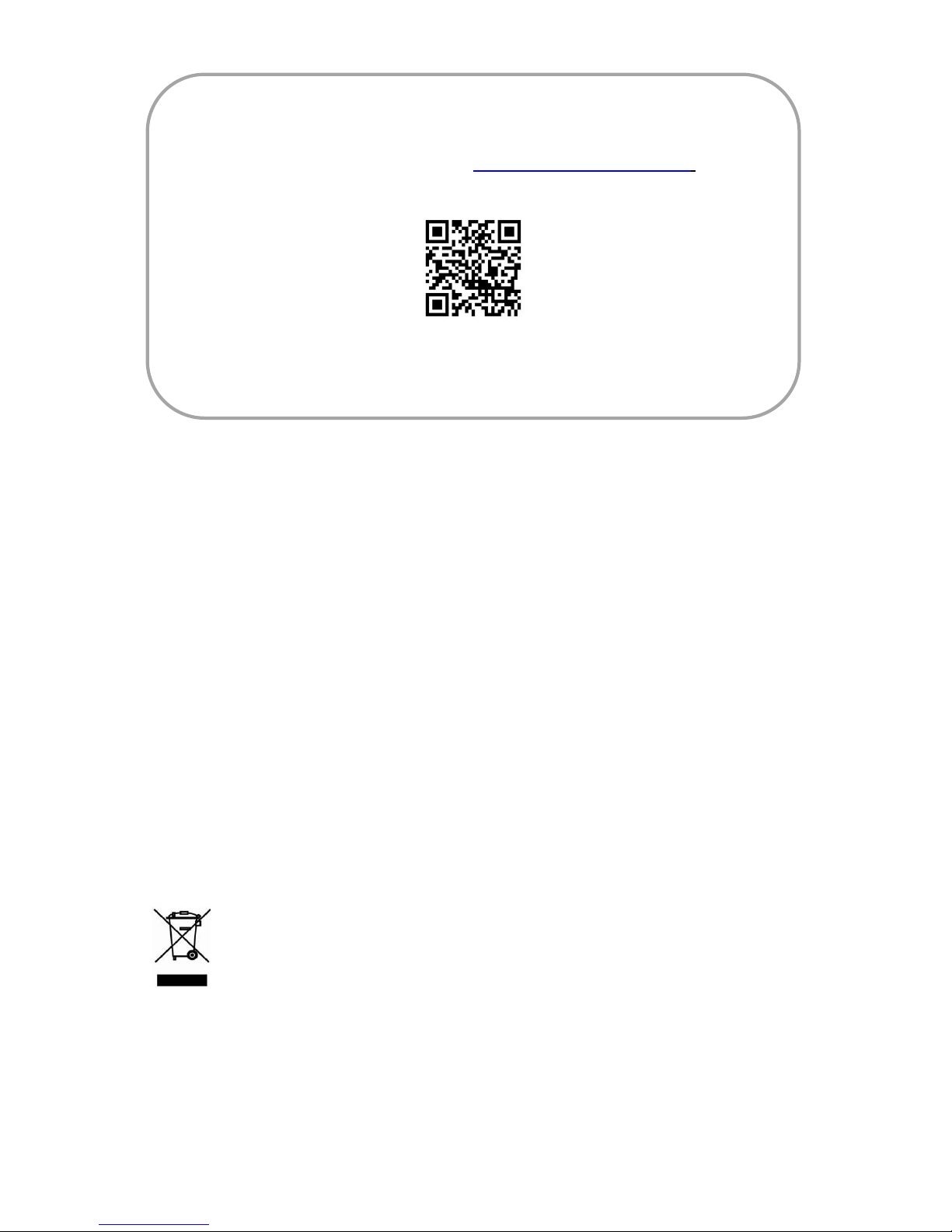
This manual can be downloaded from www.falconfoodservice.com or scan
here.
IMPORTANT: Please keep this manual for future reference.
Page 3
3
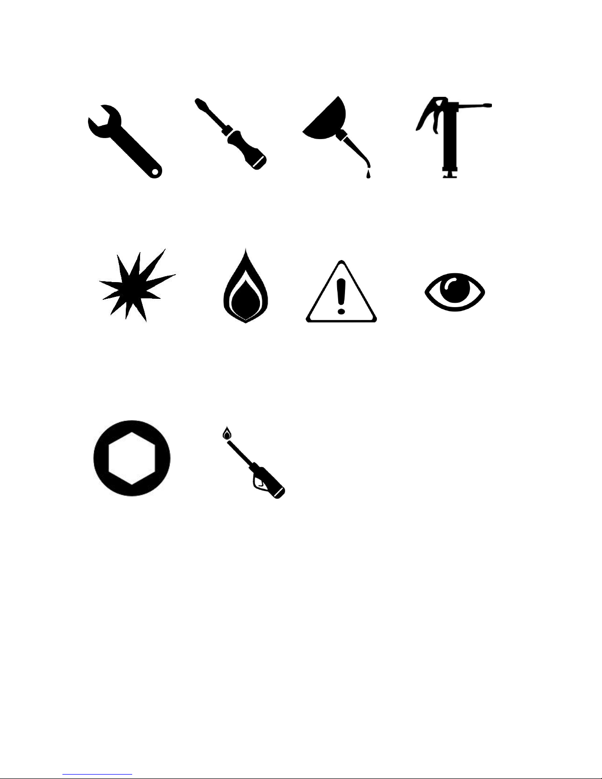
SYMBOLS
•SPANNER • SCREWDRIVER • COOKING OIL • GREASE
• SPARK IGNITION • FLAME • WARNING • VIEWPORT
• ALLEN KEY •IGNITER
Page 4

4
These instructions are only valid if the country code appears on the
appliance. If the code does not appear on the appliance, refer to the
technical instructions for adapting the appliance to the conditions for
use in that country.
Installation must meet national or local regulations. Attention must be
paid to: gas safety (installation & use) regulations, health and safety at
work act, local and national building regulations, fire precautions act.
To prevent shocks, all appliances must be earthed.
This equipment is for professional use only and must be used by
qualified persons.
The installer must instruct the responsible person(s) of the correct
operation and maintenance of the appliance.
Only competent persons are allowed to service or convert the appliance
to another gas type.
Gas appliances must have a stop cock fitted in the supply pipe work.
The user must be familiar with the location and operation of this device
in order to turn off the supply of gas in the event of an emergency.
Unless otherwise stated, parts which have been protected by the
manufacturer must not be adjusted by the installer.
Take care when moving an appliance fitted with castors.
The appliance must be serviced regularly by a qualified person. Service
intervals should be agreed with the service provider.
This appliance may be discolored due to testing.
Page 5

5
CONTENTS
1.0 APPLIANCE INFORMATION ................................ ................................ ........... 6
2.0 OPERATION ................................ ................................ ................................ .... 7
2.1 COMPONENT PARTS .................................................................................. 8
2.2 CONTROLS .................................................................................................. 9
2.3 USING THE INDUCTION HOB ................................................................ 9-10
3.0 CLEANING AND MAINTENANCE ................................................................. 11
4.0 SPECIFICATION ............................................................................................ 11
5.0 DIMENSIONS / CONNECTION LOCATION .................................................. 12
6.0 INSTALLATION .............................................................................................. 13
6.1 SITING / CLEARANCES ............................................................................. 13
6.2 ELECTRICAL SUPPLY AND CONNECTION ............................................. 14
6.3 ASSEMBLY ................................................................................................. 15
6.4 COMMISSIONING ...................................................................................... 15
6.5 INSTRUCTION TO USER ........................................................................... 15
6.4 SUITING ................................................................................................ 16-17
7.0 SERVICING AND CONVERSION .................................................................. 18
7.1 CONTROL PANEL ...................................................................................... 18
7.2 REMOVING THE GENERATOR ............................................................ 18-19
7.3 REPLACING CONTROL SWITCH/LED INDICATORS ............................... 20
7.4 HOB ASSEMBLY ........................................................................................ 21
7.5 INDUCTION COIL ASSEMBLY .............................................................. 21-22
8.0 FAULT FINDING ............................................................................................ 23
8.1 ERROR CODE TABLE .......................................................................... 23-25
9.0 CIRCUIT DIAGRAM .................................................................................. 26-27
10.0 WIRING DIAGRAM ................................................................................ 28-30
11.0 SPARE PARTS ........................................................................................... 31
12.0 SERVICE INFORMATION .......................................................................... 31
Page 6
6
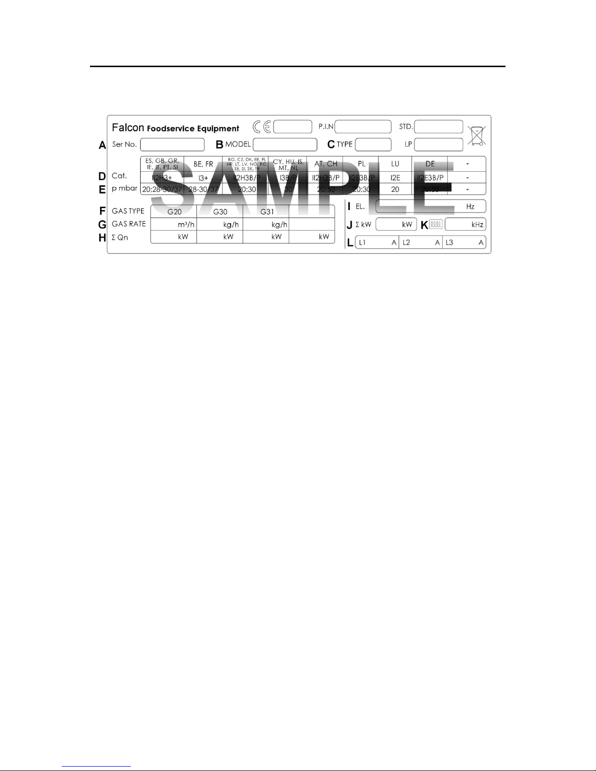
1.0 APPLIANCE INFORMATION
This appliance has been CE-marked on the basis of compliance with the relevant EU
directives for the heat inputs, gas pressures and voltages stated on the data plate.
A - Serial No •
B - Model No •
C - Flue Type •
D - Gas Category •
E - Gas Pressure •
F - Gas Type •
G - Gas Rate •
H - Total Heat Input •
I - Electrical Rating •
J - Total Electrical Power •
K - Magnetic Field Frequency •
L - Electrical Phase Loading •
Page 7
7
2.0 OPERATION
IF GLASS-CERAMIC TOP IS CRACKED OR BROKEN IMMEDIATELY
DISCONNECT APPLIANCE FROM POWER SUPPLY AND CONTACT
YOUR SERVICE AGENT.
THE AIR INTAKE FILTER MUST BE IN POSITION DURING
OPERATION IT SHOULD BE CLEANED REGULARLY AND DO NOT
OBSTRUCT AIR FILTER ENTRY BELOW.
USERS MUST BE MADE AWARE THAT INDIVIDUALS FITTED WITH A
PACEMAKER SHOULD CONSULT THEIR DOCTOR IF IN A CLOSE
PROXIMITY TO THIS UNIT. THIS INDUCTION UNIT EMANATES AN
18KHz TO 20 KHz OUTPUT THAT MAY AFFECT OLDER TYPES OF
PACEMAKER.
USE OF THE CORRECT TYPE OF PAN IS ESSENTIAL FOR
CORRECT OPERATION.
DO NOT PLACE ANY METAL OBJECTS, SUCH AS KITCHEN
UTENSILS, CUTLERY, ALUMINIUM FOIL, OR PLASTIC VESSELS, ON
THE GLASS-CERAMIC TOP.
THE USER MUST ALSO BE AWARE OF POTENTIAL TO HEAT
JEWELLERY AND DISRUPT ELECTRONIC EQUIPMENT PLACED
OVER THE INDUCTION ZONES MAGNETIC FIELD.
DO NOT PLACE CREDIT CARDS, ETC, ON THE GLASS-CERAMIC
TOP AS DATA COULD BE WIPED OFF.
NEVER LEAVE THE INDUCTION HOB UNSUPERVISED WHEN IN
USE. THE GLASS-CERAMIC TOP MUST NOT BE USED FOR
STORAGE.
DAMAGED PANS CAN REDUCE THE APPLIANCE EFFICIENCY.
Page 8
8
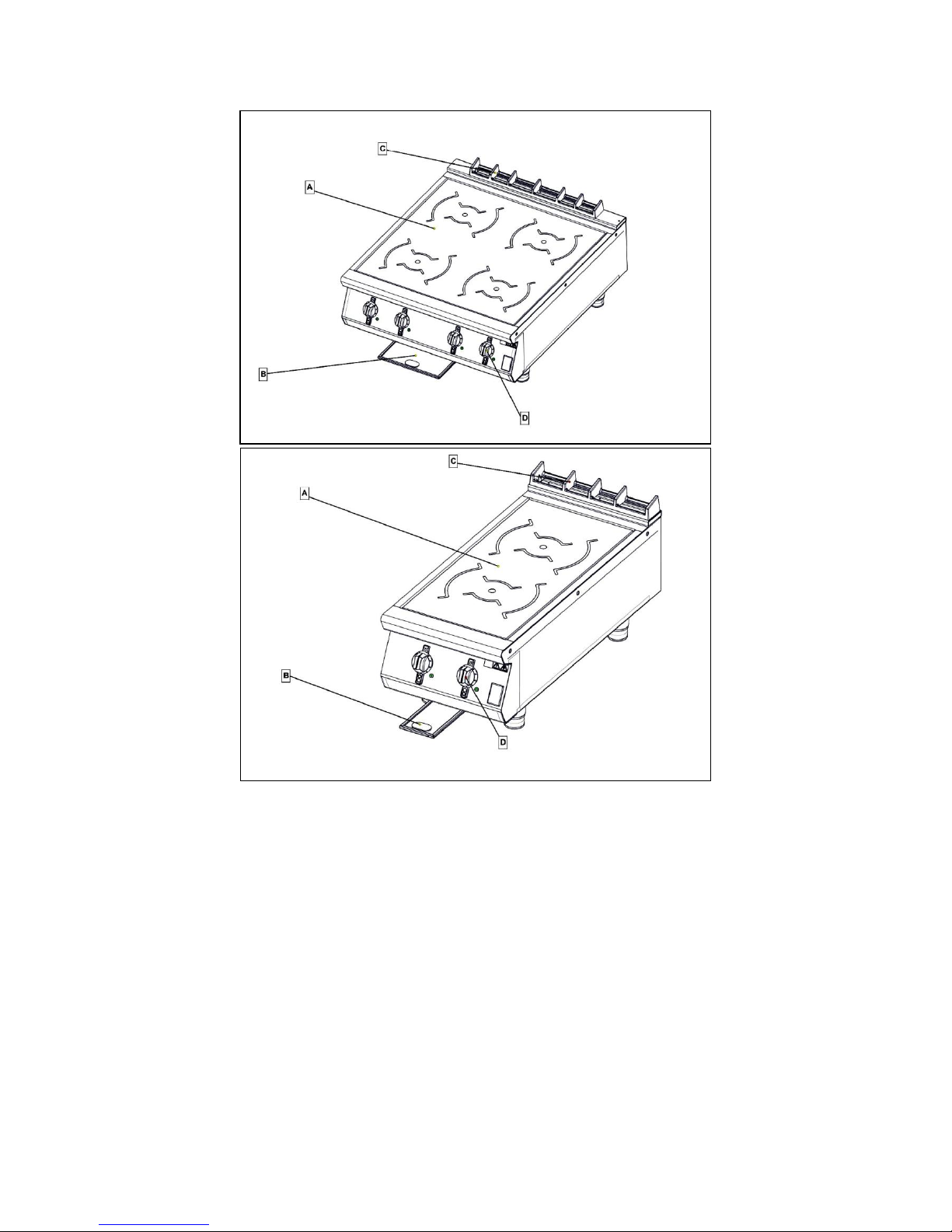
2.1 COMPONENT PARTS
A – Glass hob
B – Filter
C – Cast iron flue capper
D – Control switch
Page 9
9
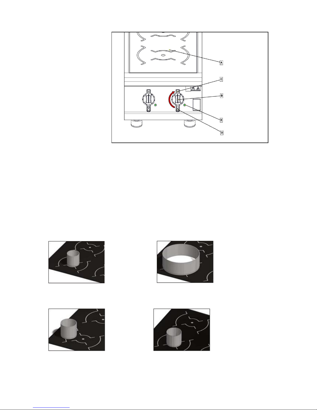
2.2 CONTROLS
A – Cooking surface.
B – Control switch.
C – Off position
D – Zone indicator
E - LED
2.3 USING THE INDUCTION HOB
2.3.1 Ensure you use the correct size of pot.
<Ø120 Ø120 – Ø270
2.3.2 Ensure the pots are central in the cooking zone
2.3.3 Ensure you use the correct type of pot
Page 10
10
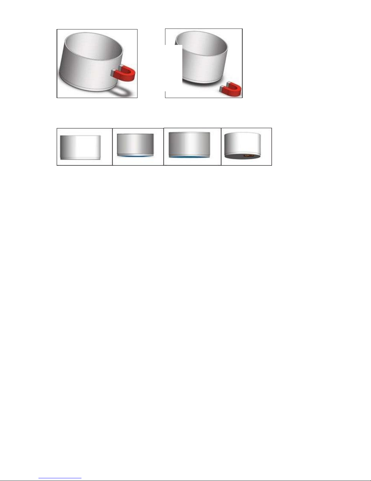
2.3.4 Ensure you use a clean flat bottom pan
2.3.5 Turn on control. The green L.E.D will light. If you remove the pot from the cooking
zone the L.E.D will flash at 1 second intervals to indicate that the cooking zone is still
active.
Page 11

11
3.0 CLEANING AND MAINTENANCE
3.1 Turn off and cool down
3.2 Clean the glass hob with hot soapy water
CLEAN THE AIR INTAKE FILTER REGULARLY. FAILURE TO
CLEAN THE FILTER REGULARLY MAY CAUSE PROBLEMS WHICH
WILL NOT BE COVERED BY WARRANTY. THE AIR INTAKE FILTER
MUST BE IN PLACE DURING OPERATION.
DO NOT ATTEMPT TO REPAIR OR REPLACE ANY PART OTHER
THAN THE AIR INTAKE FILTER. REFER TO THE ERROR CODE LIST
TO DEBUG THE PROBLEM.
4.0 SPECIFICATION
These appliances are suitable for AC supplies only.
Three phase & neutral 5 wire connection
MODEL
VOLTAGE
POWER
L1
L2
L3
I9042
400V 3N~
7kW
10.1A
10.1A
10.1A
I9043
400V 3N~
10kW
14.4A
14.4A
14.4A
I9084
400V 3N~
14kW
20.2A
20.2A
20.2A
I9085
400V 3N~
20kW
28.9A
28.9A
28.9A
Page 12

12
5.0 DIMENSIONS / CONNECTION LOCATION
Page 13

13
6.0 INSTALLATION
Electrical Safety and Advice Regarding Supplementary Electrical Protection
Commercial kitchens and foodservice areas are environments where electrical
appliances may be located close to liquids, or operate in and around damp
conditions, or where restricted movement for installation and service is evident.
The installation and periodic inspection of the appliance should only be undertaken
by a qualified, skilled and competent electrician; and connected to the correct power
supply suitable for load as stipulated by the appliance data label.
The electrical installation and connections should meet the necessary requirements
to local electrical wiring regulations and electrical safety guidelines.
We recommend:-
Supplementary electrical protection with use of a residual current device
(RCD).
Fixed wiring appliances incorporate a locally situated switch disconnector to
connect to, which is easily accessible for switching off and safe isolation
purposes. The switch disconnector must meet the specification requirements
of IEC 60947.
6.1 SITING / CLEARANCES
CAUTION: WALLS CLOSER THAN 150mm TO THE APPLIANCE
MUST BE NON COMBUSTABLE. IF SUITING THE NECESSARY
CLEARANCES TO ANY CUMBUSTIBLE WALL MUST BE THE
LARGEST FIGURE GIVEN FOR INDIVIDUAL APPLIANCES INSTRUCTIONS.
Page 14

14
6.2 ELECTRICAL SUPPLY AND CONNECTION
6.2.1 Remove control panel to access the inlet terminal (see 7.1)
6.2.2 Cable entry at unit rear. A suitable rated isolating switch with contact separation of at
least 3mm in all poles must be installed and wiring executed in accordance with relevant
regulations.
This appliance is also provided with a terminal
for connection of an external equipotential
conductor. This terminal is in effective electrical
contact with all fixed exposed metal parts of the
appliance, and shall allow the connection of
conductor having a nominal cross-section area
of up to 10mm². It is located at the rear of the
unit and identified by the following label and
must only be used for bonding purposes.
The electrical connections color code is shown in the table below.
PHASE I
PHASE II
PHASE II
NEUTRAL
EARTH
Brown
Black
Grey
Blue
Green/Yellow
MAINS INPUT CONNECTION CABLE IS NOT SUPPLIED; SUITABLE
CABLE WILL CONFORM TO CODE DESIGNATION IEC 60245-57.
Page 15

15
6.3 ASSEMBLY
6.3.1 Unpack, position appliance and level using feet adjusters as shown below.
6.3.2 Ensure fan intake filter is fitted and secured in position below control panel.
6.3.3 Connect to an electrical supply (see 6.2)
6.4 COMMISSIONING
6.4.1 Switch all cooking zones on to position 10.
6.4.2 Ensure all L.E.Ds light and begin to flash.
6.4.3 Place a pan suitable for induction cooker tops, filled with water, upon a cooking zone.
The pan minimum diameter cannot be less than 120mm.
6.4.4 Ensure that corresponding L.E.D stops flashing and remains lit. This indicates that
“Pan detection” feature is working.
6.4.5 Repeat on all different cooking zones.
6.4.6 Leave pots to heat until water boils and switch controls to maintain simmer.
6.4.7 Switch control off.
6.5 INSTRUCTION TO USER
After installation and commissioning is completed, please hand the user instructions
to the user and ensure that the person/s responsible understand the instructions
regarding correct operation and cleaning of the appliance.
PLEASE FILL OUT THE INFORMATION TABLE ON THE FRONT
COVER AFTER COMMISSIONING.
Page 16

16
6.4 SUITING
“Patent No. GB 2540131”
6.6.1 Before leveling and suiting units ensure the units are fully built, including all
accessories and castings.
6.6.2 Undo the 4 fixing screws on the control panel and remove.
6.6.3 Remove the hob rear infill and replace with rear suiting plate and fixings.
6.6.4 Remove the front side panel countersunk screw and suiting plate.
NOTE: The DLS system is designed to give a quick and easy suiting
solution. If you require an improved seal between appliances we
recommend you use, a food grade, high temperature silicon
sealant. This can be supplied by Falcon part no – 523400021
6.6.5 Run a bead of silicon 5mm from profile edge as highlighted below.
Page 17

17
6.6.6 Slide suited units into position.
6.6.7 (A) Right hand unit: Screw the M5 x 40 screw (supplied in the kit) into one of
the suiting plates as shown and then insert through the front fixing holes of
both units.
6.6.8 (B) Left hand unit: Slide the penny and lock washer on to the screw and
secure using the M5 nut.
6.6.9 (C) Remove the front bolts from feet, insert base tie plate and secure the bolts
back into position.
6.6.10 (D) Replace fixings on the rear hob and tighten screw caps into position.
6.6.11 Replace control panel. .
A
D
B
C
Page 18

18
7.0 SERVICING AND CONVERSION
BEFORE ATTEMPTING ANY MAINTENANCE, ISOLATE THE APPLIANCE AT
THE MAINS ISOLATING SWITCH AND TAKE STEPS TO ENSURE THAT IT
CANNOT BE INADVERTENTLY SWITCHED ON.
7.1 CONTROL PANEL
7.1.1 Remove control panel as shown.
7.2 REMOVING THE GENERATOR
7.2.1 i9042/i9043 - Remove the control panel see 7.1.
7.2.2 Remove the hob see 7.4.
7.2.3 Disconnect the power cables to the generator.
7.2.4 Unscrew the 4 hex bolts and remove.
Page 19

19
7.2.5 i9084/i9085 – Remove the control panel see7.1.
7.2.6 Remove the filter.
7.2.7 Remove the cable access panels.
7.2.8 Disconnect the power cables to the generator and coils.
7.2.9 Unscrew the fixings holding the generator mounting plate and remove.
7.2.10 Unscrew the fixings holding the generator and remove.
Page 20

20
7.3 REPLACING CONTROL SWITCH/LED INDICATORS
7.3.1 Remove control panel, see 7.1
7.3.2 Control switch:- Identify wires that relate to switch and L.E.D attached to generator
unit and disconnect.
7.3.3 Unscrew and remove as shown.
7.3.4 Re-assemble in reverse order.
7.3.5 LED’s are polarity driven with the Green cable negative and the purple cable positive.
The Green cable connects to the spade terminal above L.E.D body flat side.
7.3.6 Unscrew the fixing nut and remove as shown.
Page 21

21
7.4 HOB ASSEMBLY
7.4.1 Remove the control panel see 7.1.
7.4.2 Remove the hob assembly as shown. Note: It is recommended that two persons
carry out the procedure.
7.5 INDUCTION COIL ASSEMBLY
DO NOT USE THE UNIT IF THE CERAMIC TOP IS CHIPPED,
CRACKED OR BROKEN. THE PANEL NEEDS TO BE REPLACED.
WHEN REPLACING COILS, ENSURE THAT SPACERS ARE IN
POSITION AND ONLY FITTED WITH A SINGLE, LAYERED
SPACER AS INDICATED.
THE INDUCTION GENERATOR UNIT IS HEAVY AND IT MAY BE
REQUIRED THAT TWO PEOPLE ARE INVOLVED WITH THE
CHANGING PROCEDURE.
Page 22

22
7.5.1 Unscrew the fixings holding the coil carrier on to the hob and remove.
7.5.2 Disconnect the wires to the coil.
7.5.3 Remove the four fixings holding the coil to the carrier taking care not to loose the
springs.
Page 23

23
8.0 FAULT FINDING
Note: Most faults can be rectified by simply switching unit off for 10 seconds. After
this time, turn power back on at mains supply. If fault continues to occur after such
action then please refer to the table. This will provide a solution to rectify the
condition.
8.1 ERROR CODE TABLE
If any fault becomes apparent during the tests, an error code may display on an LED
as a series of flashes. These flashes correspond to the numbers in the left column of
the following table.
For example, 6 short flashes followed by a long flash would indicate error code 06 –
“internal temperature too high”.
CODE
ERROR
CAUSE
ACTION
01
Coil Pan Detection
Error.
Use of Unsuitable pan material
Use suitable pan.
Reset appliance
Switch appliance OFF for 10
seconds then ON.
Defective coil
Check all electrical
connections to the inductor coil
Replace defective Coil
02
No Inductor Coil
Current.
Reset appliance
Switch appliance OFF for 10
seconds then ON.
Inductor Coil connection failure
Check all electrical
connections to the inductor coil
Replace defective Coil
03
Generators Internal
Heat Sink Too High.
Reset appliance
Switch appliance OFF for 10
seconds then ON.
Air routes blocked.
Check below appliance & rear
of Appliance for potential Air
Flow Obstructions.
Air Filter blocked (Requires
Cleaning).
Check Filter - Does it require
cleaning / Replacing?
Generator Fan(s) Malfunctioned.
Due to electrical fault.
Replace Generator
Generator Fan(s) blowing instead
of sucking.
Replace Generator
Generator Temperature sensor
defective.
Replace Generator -
Page 24

24
04
Cooking Zone
Temperature Too
High Or Remains
Constant During
Cooking.
Reset Appliance
Switch Appliance OFF for 10
Seconds then On.
Pan empty / Too Hot
Test Disc may be overheated –
allow for cooling.
Cooking Zone Self Protected due
to Abnormal Heat Build up
Allow Cook Zone to cool for
couple of Minutes
Temperature sensor faulty
(Constantly records a Ambient
Temperature)
Check all electrical
connections to the inductor coil
Replace defective Coil
05
Controls Failure
Reset Appliance
Switch Appliance OFF for 10
Seconds then On.
Controls faulty or incorrectly
Wired
Check all electrical
connections to the controls &
Generator
Replace defective Controls
Assembly
06
Generators Internal
Temperature Too
High.
Reset Appliance
Switch Appliance OFF for 10
Seconds then On.
See Fault 3
See Fault 3
07
Cooking Zone
Temperature Sensor
Reset Appliance
Switch Appliance OFF for 10
Seconds then On.
Temperature sensor faulty /
Malfunctioned
Check all electrical
connections to the inductor coil
Replace defective Coil
08
Mains Supply Failure
Reset Appliance
Switch Appliance OFF for 10
Seconds then On.
Fault in mains supply
Is there a Phase(s) Down
Has supply been interrupted
intermittently?
Has supply Spiked?
Has Supply Under / Over
Voltage?
09
N/A
N/A
N/A
10
Communication Error
Reset Appliance
Switch Appliance OFF for 10
Seconds then On.
Failure on LIN or CAN-Bus
Check all communications
connections
Page 25

25
11
Initialisation Error
Reset Appliance
Switch Appliance OFF for 10
Seconds then On.
Software Failure while initialising
hardware
Wait. The generator will reset
every 30 seconds.
Replace Generator .
12
Current Reading
Failure
Reset Appliance
Switch Appliance OFF for 10
Seconds then On.
Generator suspects Current
being generated does not reflect
what appliance controls are set
for.
Check Mains Supply
Check all electrical
connections within appliance.
Replace Suspect Coil
Replace Generator .
13
Mains Connection
Error
Reset Appliance
Switch Appliance OFF for 10
Seconds then On.
Mains voltage too high or too low
See Fault 8
14
Mains Connection
Error
Reset Appliance
Switch Appliance OFF for 10
Seconds then On.
Mains voltage too high or too low
See Fault 8
15
Coil Electrical Circuit
Self-Protected.
Reset Appliance
Switch Appliance OFF for 10
Seconds then On.
See Fault 4
See Fault 4
Page 26

26
9.0 CIRCUIT DIAGRAM
i9042/3 Circuit Diagram
Page 27

27
i9084/5 Circuit Diagram
Page 28

28
10.0 WIRING DIAGRAM
i9042/3 Wiring diagram
Page 29

29
i9084/5 Wiring diagram
Page 30

30
i9084/85 Coil Wiring Diagram
Page 31

31
11.0 SPARE PARTS
Main Spare Parts
LED
Hob Control Switch
Hob control Knob
Induction Generator
MCB
When ordering spare parts please quote the following;
Model Number
Serial Number
This information will be found on the data plate attached to the appliance. (see1.0)
12.0 SERVICE INFORMATION
It is recommended to have a maintenance contract with a local service provider.
SERVICELINE CONTACT:
(UK only)
Phone: +441438 363 000
Warranty Policy Shortlist
For our warranty policy please go to www.falconfoodservice.com
 Loading...