

Falcon F900 SERIES, G9541R, G9541CR, G9581, G9581R User, Installation And Servicing Instructions
...Page 1

1
F900 SERIES
User, installation and servicing instructions
GAS GRIDDLE
G9541, G9541R, G9541CR, G9581, G9581R, G9581CR
Read these instructions before use
T100891
DATE PURCHASED:
MODEL NUMBER:
SERIAL NUMBER:
DEALER:
SERVICE PROVIDER:
REV. 2
Published: 31/03/2016
Page 2

2
Falcon Foodservice Equipment
HEAD OFFICE
Wallace View, Hillfoots Road, Stirling. FK9 5PY. Scotland.
WEEE Directive Registration No. WEE/DC0059TT/PRO
At end of appliance life, dispose of appliance and any replacement parts in a safe
manner, via a licensed waste handler. Appliances are designed to be dismantled
easily and recycling of all material is encouraged whenever practicable.
Dear Customer,
Thank you for choosing Falcon Foodservice Equipment.
This manual can be downloaded from www.falconfoodservice.com or scan
here.
IMPORTANT: Please keep this manual for future reference.
Page 3

3
SYMBOLS
• SPANNER • SCREWDRIVER • COOKING OIL • GREASE
• SPARK IGNITION • FLAME • WARNING • VIEWPORT
• ALLEN KEY •IGNITER
Page 4

4
These instructions are only valid if the country code appears on the
appliance. If the code does not appear on the appliance, refer to the
technical instructions for adapting the appliance to the conditions for use
in that country.
Installation must meet national or local regulations. Attention must be paid
to: gas safety (installation & use) regulations, health and safety at work act,
local and national building regulations, fire precautions act.
To prevent shocks, all appliances must be earthed.
This equipment is for professional use only and must be used by qualified
persons.
The installer must instruct the responsible person(s) of the correct
operation and maintenance of the appliance.
Only competent persons are allowed to service or convert the appliance to
another gas type.
Gas appliances must have a stop cock fitted in the supply pipe work. The
user must be familiar with the location and operation of this device in order
to turn off the supply of gas in the event of an emergency.
Unless otherwise stated, parts which have been protected by the
manufacturer must not be adjusted by the installer.
Take care when moving an appliance fitted with castors.
The appliance must be serviced regularly by a qualified person.
Service intervals should be agreed with the service provider.
This appliance may be discolored due to testing.
Page 5

5
CONTENTS
1.0 APPLIANCE INFORMATION ..................................................................................... 6
2.0 OPERATION .............................................................................................................. 7
2.1 COMPONENT PARTS ............................................................................................ 7
2.2 CONTROLS ............................................................................................................ 7
2.3 USING THE APPLIANCE ....................................................................................... 8
3.0 CLEANING AND MAINTENANCE .............................................................................. 9
4.0 SPECIFICATION ........................................................................................................ 9
5.0 DIMENSIONS / CONNECTION LOCATIONS ........................................................... 10
6.0 INSTALLATION ........................................................................................................ 11
6.1 SITING / CLEARANCES ....................................................................................... 11
6.2 VENTILATION ...................................................................................................... 11
6.3 GAS SUPPLY & CONNECTION ........................................................................... 12
6.4 ASSEMBLY .......................................................................................................... 13
6.5 COMMISSIONING ................................................................................................ 13
7.0 CONVERSION ......................................................................................................... 14
7.1 GAS CONVERSION CHECK LIST ....................................................................... 14
8.0 SERVICING ............................................................................................................. 14
8.1 CONTROL PANEL ................................................................................................ 14
8.2 ACCESS PANEL .................................................................................................. 15
8.3 INJECTORS ......................................................................................................... 15
8.4 PILOT REMOVAL ................................................................................................. 16
8.5 PILOT ASSEMBLY ............................................................................................... 16
8.6 GAS VALVE.......................................................................................................... 17
8.7 PRESSURE ADJUSTMENT ................................................................................. 18
8.8 SAFETY THERMOSTAT REMOVAL .................................................................... 18
8.9 PLATE / THERMOSTAT BULB REMOVAL........................................................... 19
8.10 BURNER .............................................................................................................. 23
8.11 GOVERNOR ......................................................................................................... 23
9.0 FAULT FINDING ...................................................................................................... 24
10.0 SPARE PARTS ........................................................................................................ 25
11.0 SERVICE INFORMATION ........................................................................................ 25
Page 6

6
1.0 APPLIANCE INFORMATION
This appliance has been CE-marked on the basis of compliance with the relevant EU
directives for the heat inputs, gas pressures and voltages stated on the data plate.
A - Serial No
B - Model No
C - Flue Type
D - Gas Category
E - Gas Pressure
F - Gas Type
G - Gas Rate
H - Total Heat Input
I - Electrical Rating
J - Total Electrical Power
K - Magnetic Field Frequency
L - Electrical Phase Loading
Page 7
7
2.0 OPERATION
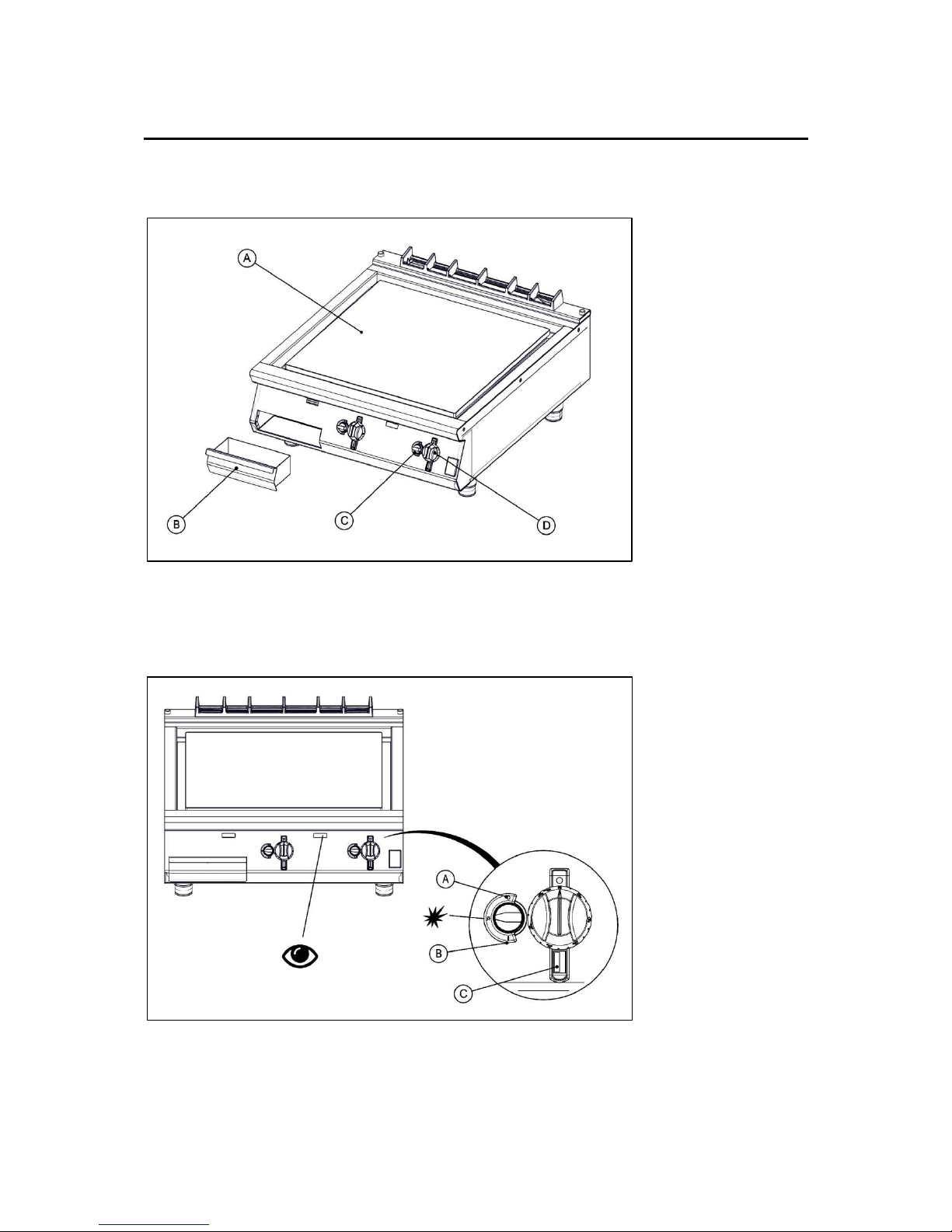
2.1 COMPONENT PARTS
2.2 CONTROLS
A – Cooking Plate
B – Fat Jug
C – Gas Control
D – Temperature Control
A – Gas OFF
B – Gas ON
C – Zone Indicator
Page 8

8
2.3 USING THE APPLIANCE
2.3.1 Before use, clean the appliance. See section 3.
2.3.2 Ignite the burners as shown. Push the knob in to turn.
2.3.3 Use temperature control knob to adjust temperature.
2.3.4 The minimum temperature of the hottest point of the plate is as follows:
G9541, G9541R, G9581, G9581R
G9541CR, G9581CR
Temperature
290°C
260°C
IF A BURNER TURNS OFF, WAIT 3 MINUTES BEFORE RELIGHTING.
2.3.5 Turning The Burner Off
Turn pilot knob to ‘OFF’ position. Look through the view port to make sure the burner
is off.
Page 9
9
3.0 CLEANING AND MAINTENANCE
3.1 Turn off and cool down.
3.2 Scrape off burnt on food.
3.3 Remove other debris using a cloth.
3.4 Clean fat jug.
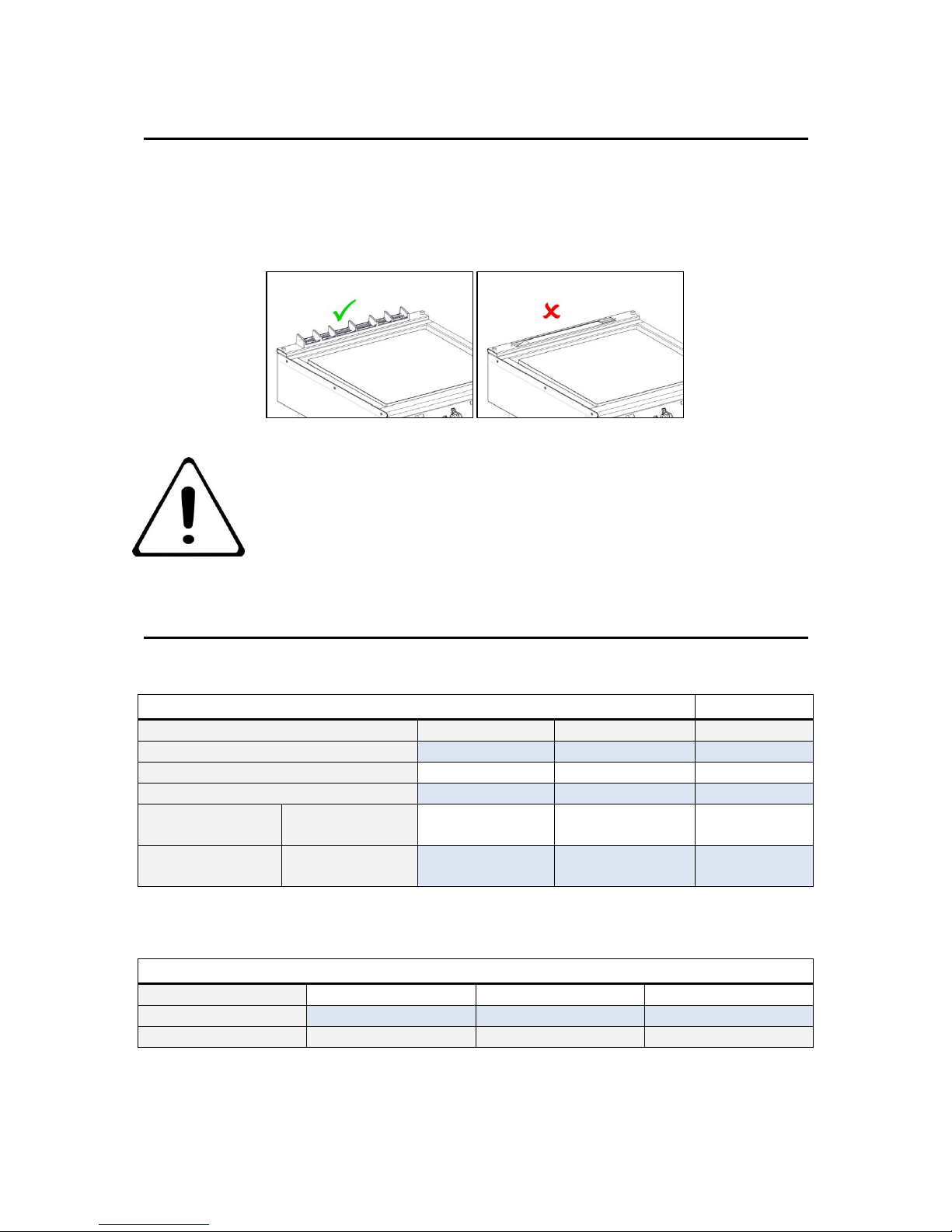
3.5 The flue capper can be removed for cleaning, but must be replaced for use.
DO NOT USE METAL UTENSILS ON CHROME GRIDDLE.
FAILURE DUE TO LACK OF PROPER CLEANING IS NOT
COVERED BY WARRANTY.
4.0 SPECIFICATION
INJECTOR SIZES
Gas Type
G20
G30
G31
G9541
2.25
1.50
1.50
G9581
2.25
1.50
1.50
Pilot Injectors
31.2
25
25
Supply
Pressure
mbar
20
29/50
37
Operating
Pressure
mbar
15
29
37
HEAT INPUTS (kW)
G20
G30
G31
G9541
8.2
8.8
8.8
G9581
16.4
17.6
17.6
Page 10
10
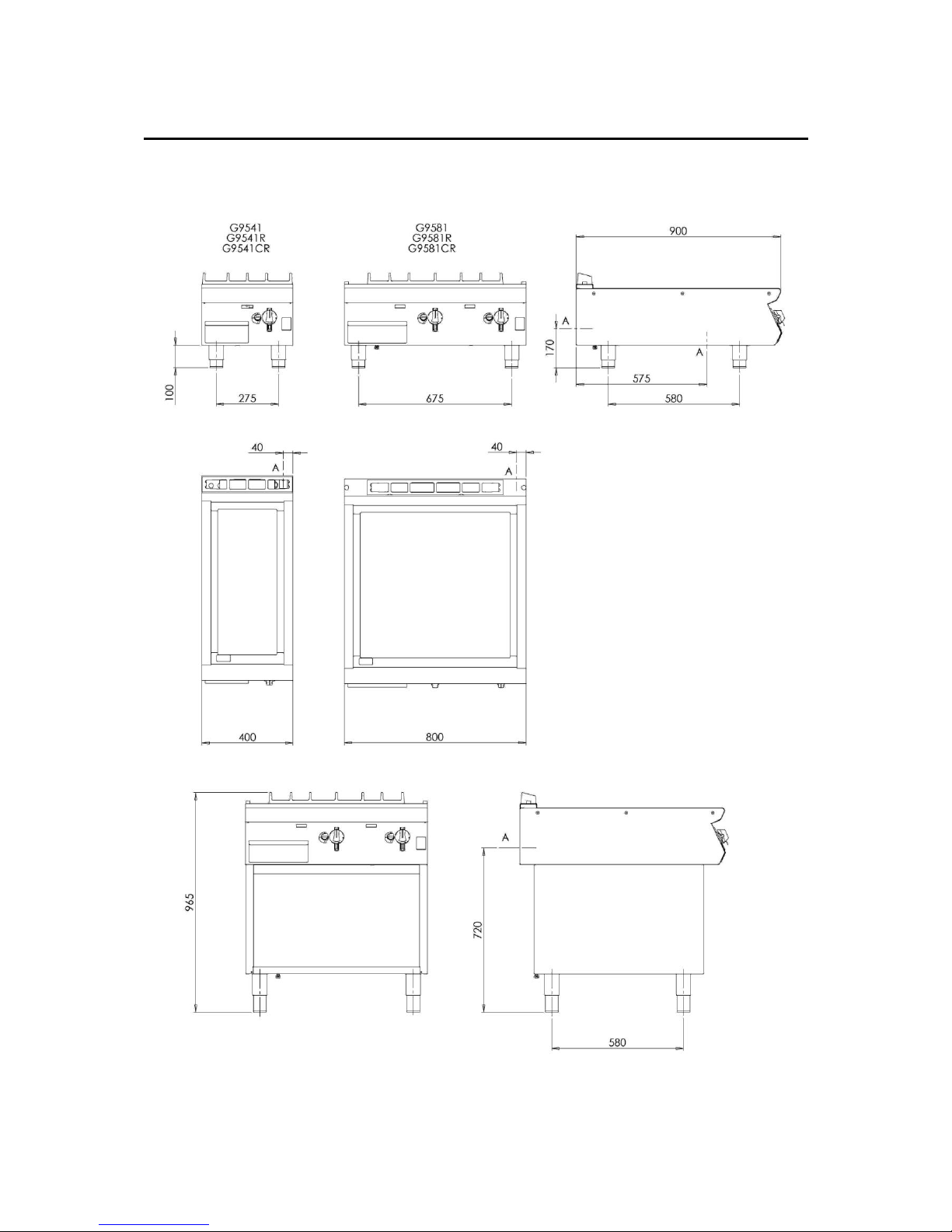
5.0 DIMENSIONS / CONNECTION LOCATIONS
A – GAS INLET
Page 11
11
6.0 INSTALLATION
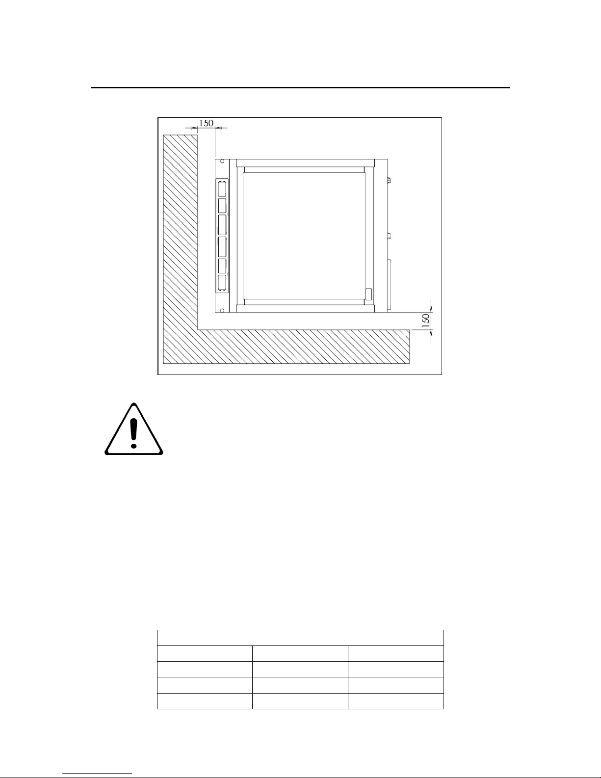
6.1 SITING / CLEARANCES
CAUTION: WALLS CLOSER THAN 150mm TO THE APPLIANCE
MUST BE NON COMBUSTIBLE. IF SUITING THE NECESSARY
CLEARANCES TO ANY CUMBUSTIBLE WALL MUST BE THE
LARGEST FIGURE GIVEN FOR INDIVIDUAL APPLIANCES
INSTRUCTIONS.
6.2 VENTILATION
This appliance must be installed with sufficient ventilation to prevent the occurrence of
unacceptable concentrations of substances harmful to health in the room in which they are
installed. Installer must consult any additional local / national regulations.
COMBUSTION AIR REQUIREMENTS
G9541
G9581
G20
8m3/h
15m3/h
G30
8m3/h
16m3/h
G31
8m3/h
16m3/h
Page 12
12
6.3 GAS SUPPLY & CONNECTION
6.3.1 Installation pipe work should be fitted in accordance with local / national standards.
The pipe work must not be smaller than unit gas inlet connection, i.e. Rp¾ (¾”
B.S.P.). If using flexible hosing, the hose must be sized to conform with the hose
manufacturers specifications and the length must not exceed 1.5m. An isolating valve
must be located close by for shut-down during an emergency or servicing.
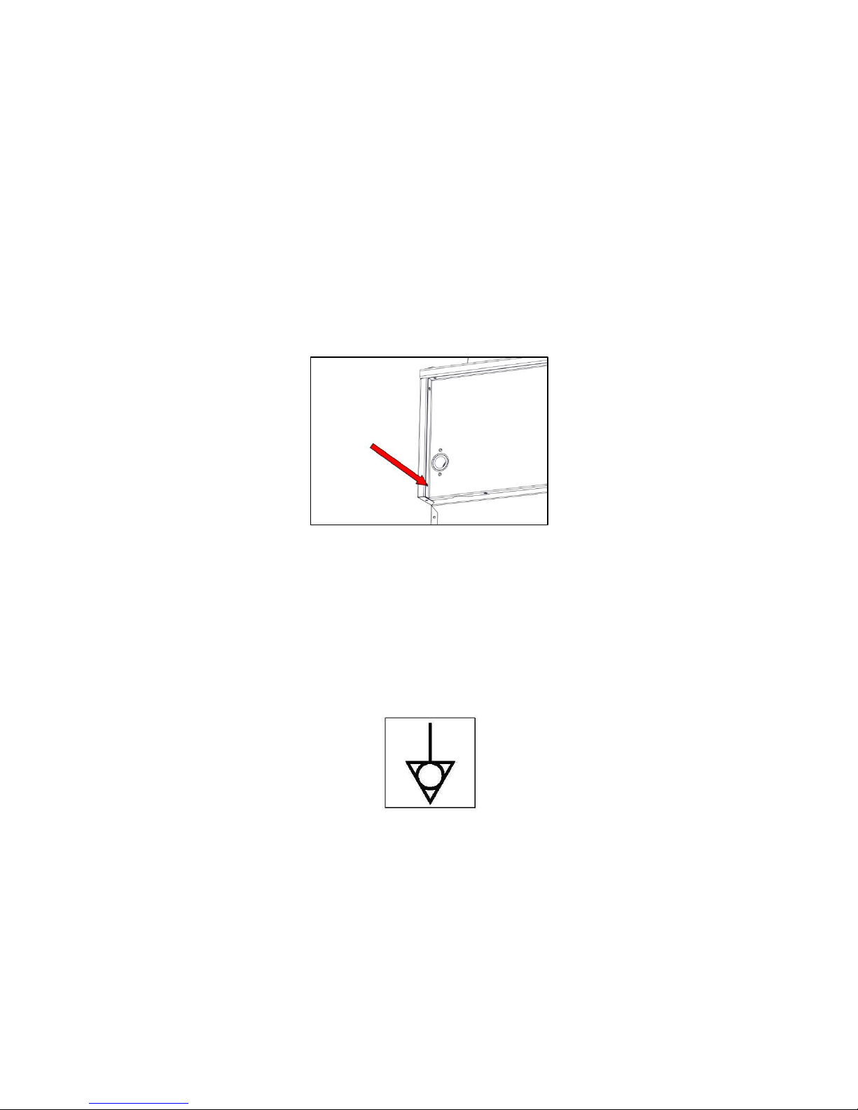
6.3.2 If flexible hose is used, it shall comply with national requirements. These must be
periodically examined and replaced as necessary. If a retention chain is required
then attach this to the fixing shown below.
6.3.3 This appliance is also provided with a terminal for connection of an external
equipotential conductor. This terminal is in effective electrical contact with all fixed
exposed metal parts of the appliance, and shall allow the connection of conductor
having a nominal cross-section area of up to 10mm². It is located at the rear of the
unit and identified by the following label and must only be used for bonding purposes.
Page 13
13
6.4 ASSEMBLY
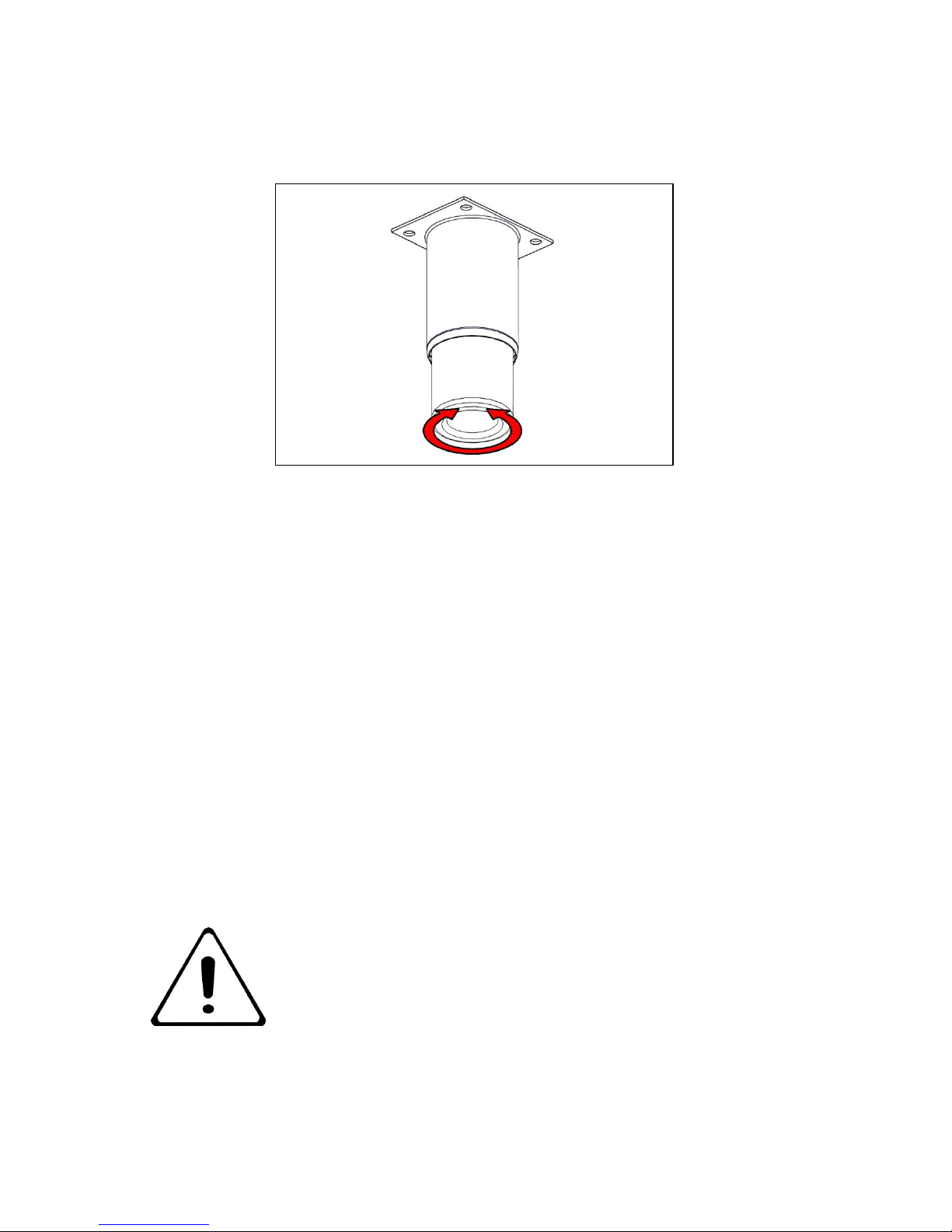
6.4.1 Position appliance and level using feet adjusters as shown below.
6.4.2 Connect appliance to gas supply and test for gas tightness (see 6.3)
6.5 COMMISSIONING
6.5.1 Remove control panel (see 8.1)
6.5.2 Ensure burner pressure is correct (see 8.7 for pressure adjustment)
6.5.3 Light pilots and ensure all stay lit.
6.5.4 Turn on main burners. Ensure correct cross lighting occurs.
6.5.5 Check for flame stability.
6.5.6 Operate controls ensuring they turn smoothly.
6.5.7 Turn off appliance.
6.5.8 Replace control panel.
If the appliance does not operate correctly please refer to section 9.0 and rectify the
problem.
PLEASE FILL OUT THE INFORMATION TABLE ON THE
FRONT COVER AFTER COMMISSIONING.
Page 14
14
7.0 CONVERSION
BEFORE INSPECTION, SERVICING OR CONVERSION, TURN OFF
GAS AT ISOLATOR.
7.1 GAS CONVERSION CHECK LIST
Change injectors in burner(s) and pilot(s) (see 8.3 & 8.5).
Change gas type label.
For G30 (50mb) fit Governor (see 8.11).
Adjust pressure at valve to values stated in section 4.0 (see 8.7 for pressure
adjustment).
8.0 SERVICING
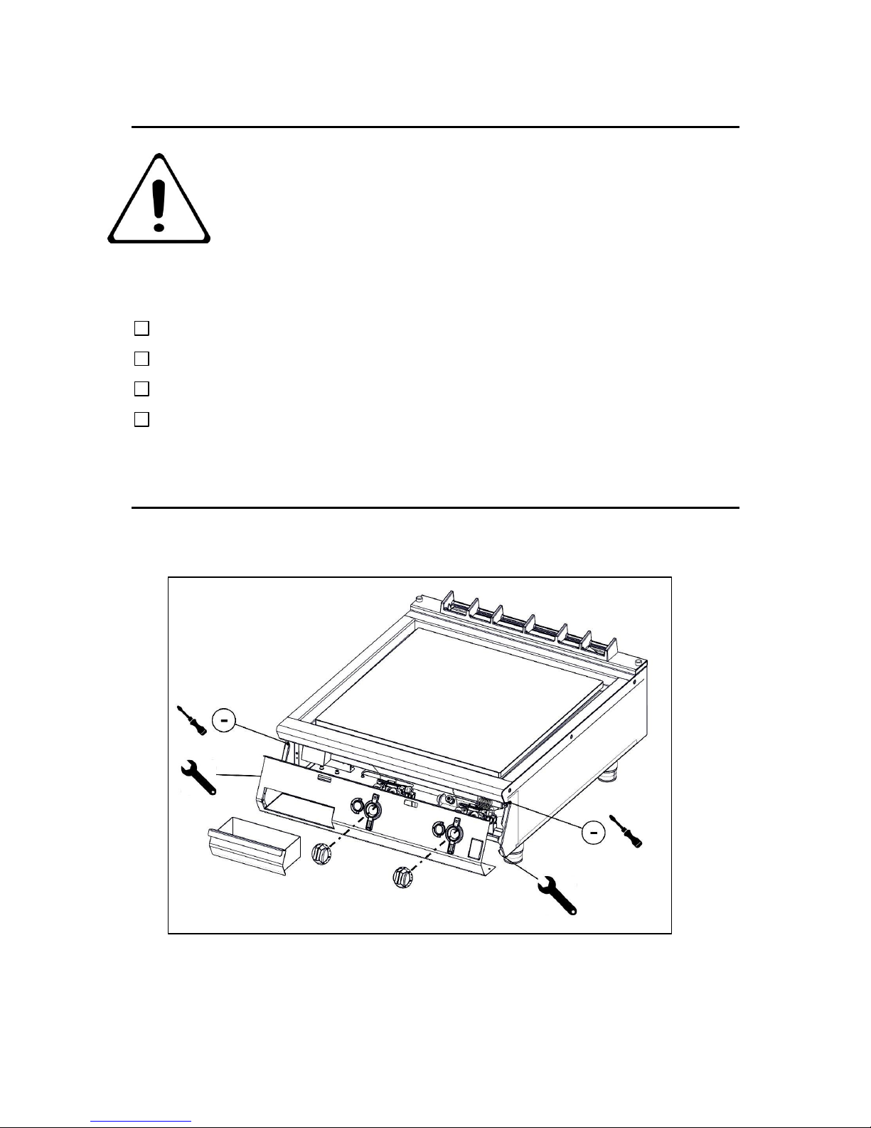
8.1 CONTROL PANEL
8.1.1 Remove control panel as shown.
Page 15
15
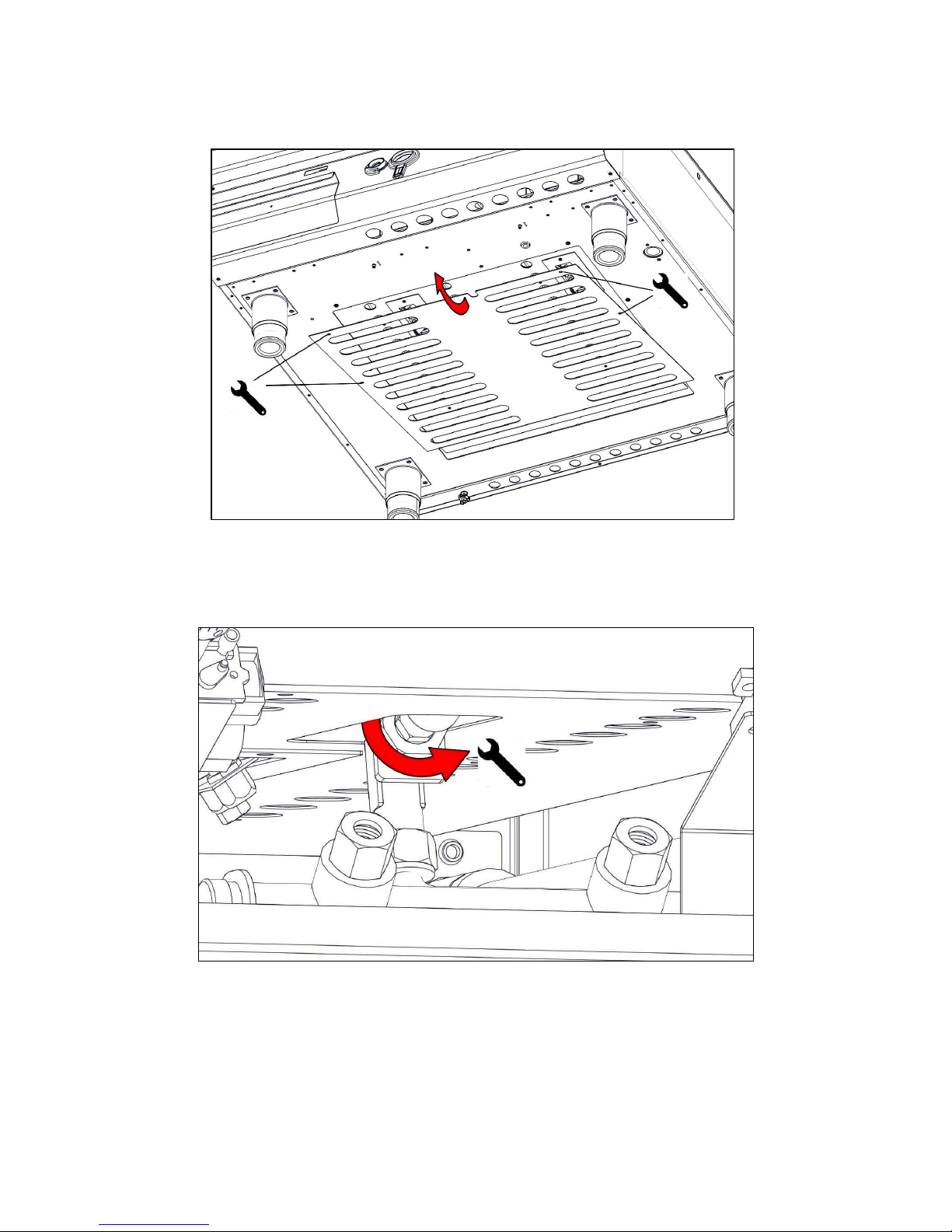
8.2 ACCESS PANEL
8.2.1 Remove access panel as shown.
8.3 INJECTORS
8.3.1 Remove injector as shown.
8.3.2 Clean injector.
8.3.3 After replacement, check burner performance.
Page 16
16
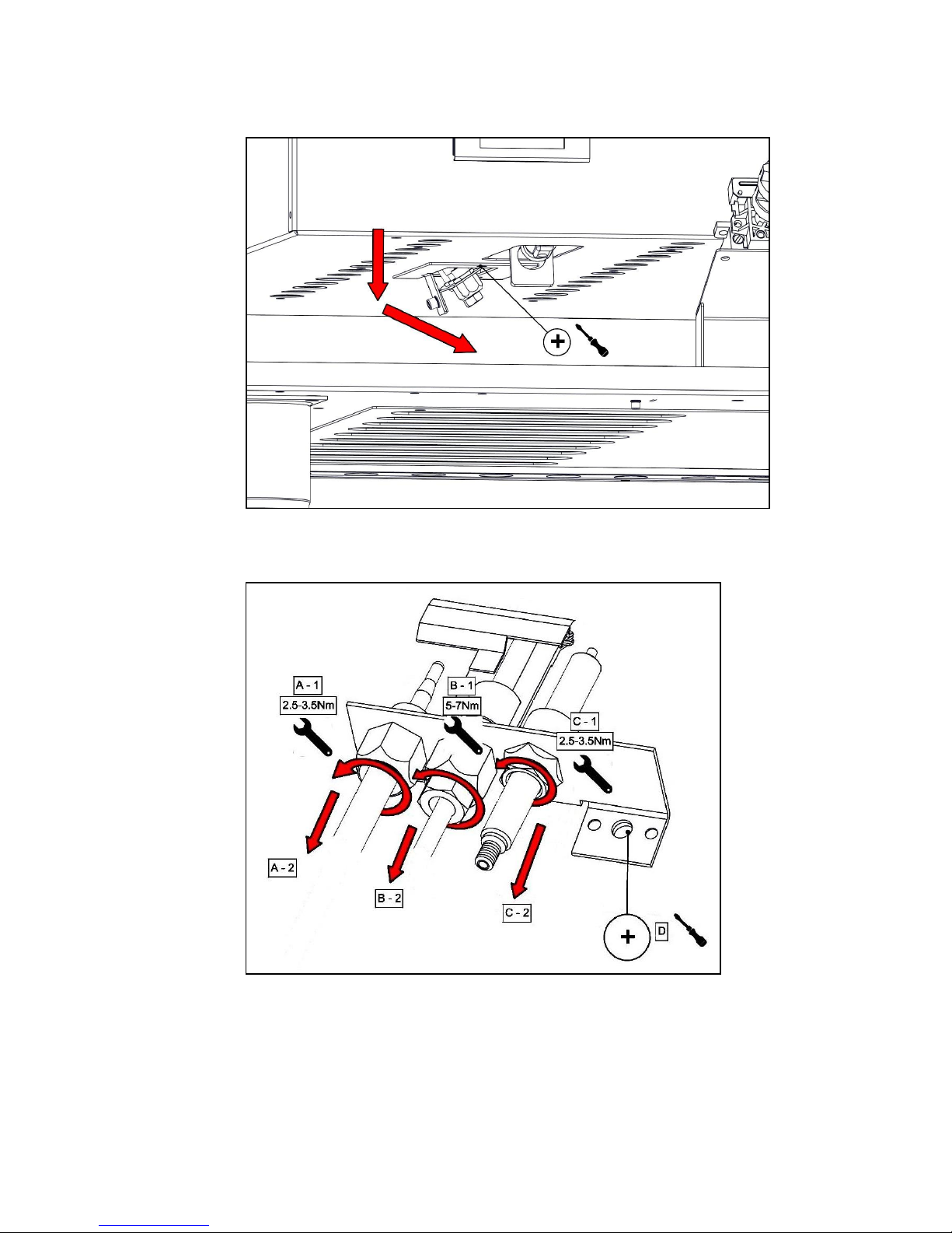
8.4 PILOT REMOVAL
8.4.1 Remove as shown.
8.5 PILOT ASSEMBLY
8.5.1 Remove pilot components as shown.
A – Thermocouple
B – Pilot Gas Pipe / Pilot Injector.
C – Spark Electrode
D – Pilot Bracket
Page 17
17
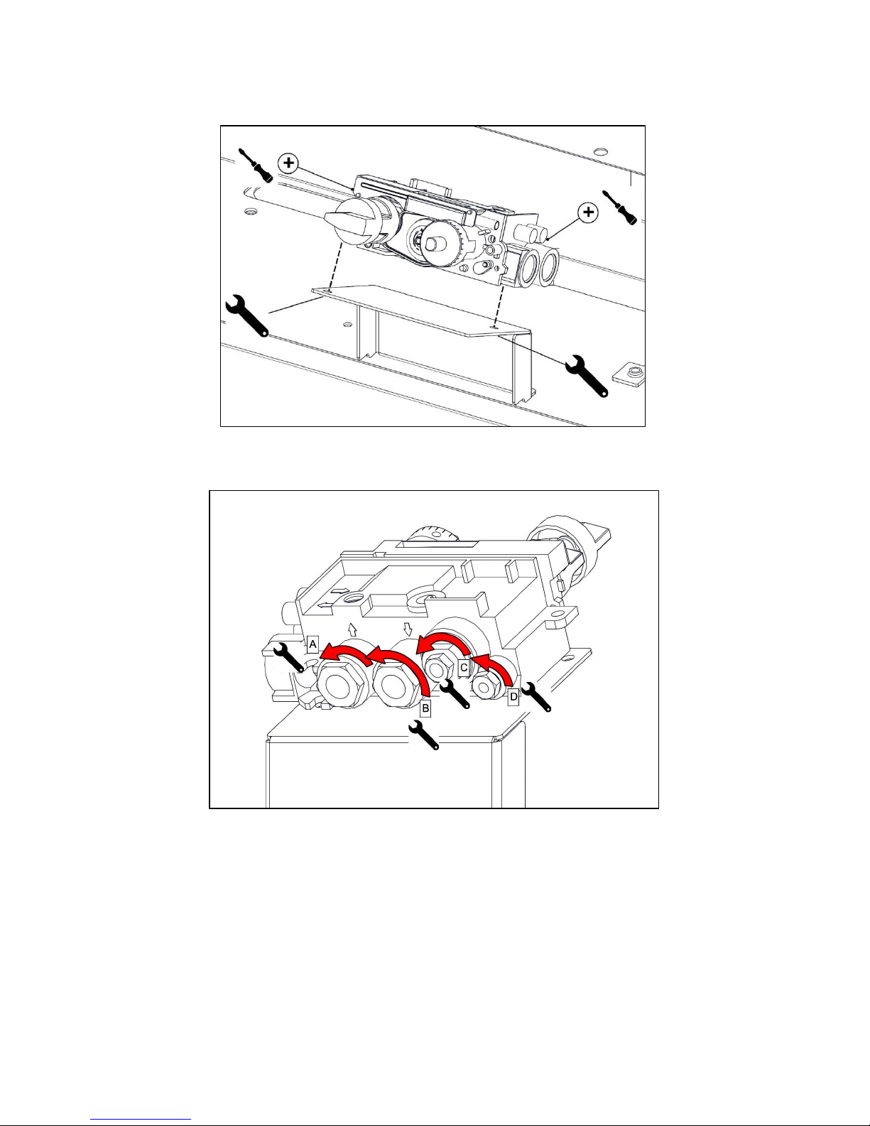
8.6 GAS VALVE
8.6.1 Remove gas valve as shown.
8.6.2 Remove connections as shown.
A – Gas In
B – Gas Out
C – Thermocouple
D – Pilot
Page 18
18
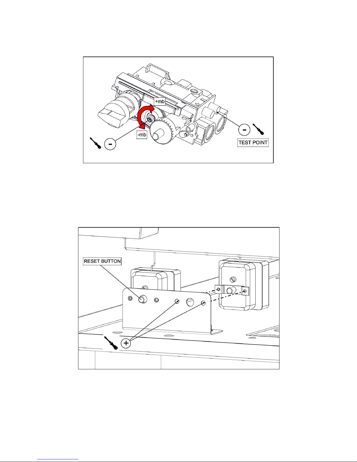
8.7 PRESSURE ADJUSTMENT
8.7.1 Adjust pressure as shown.
8.8 SAFETY THERMOSTAT REMOVAL
8.8.1 Remove safety thermostat as shown.
Page 19
19
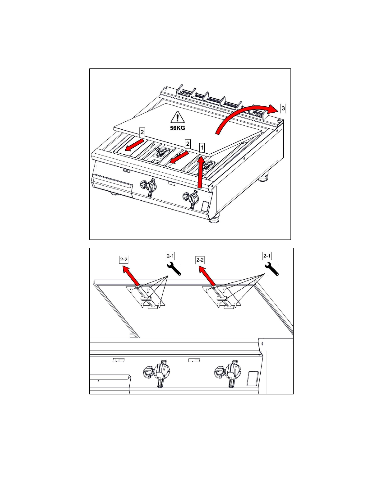
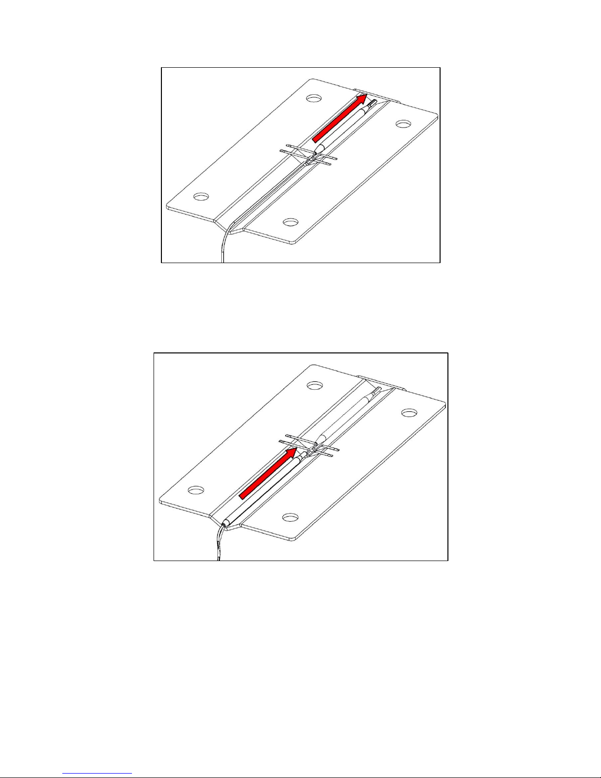
8.9 PLATE / THERMOSTAT BULB REMOVAL
8.9.1 Remove plate and thermostat phial(s) as shown.
Page 20
20
8.9.2 Replace safety thermostat phial, position as shown (Only for Chrome Griddles).
8.9.3 Replace operating thermostat phial, position as shown.
Page 21
21
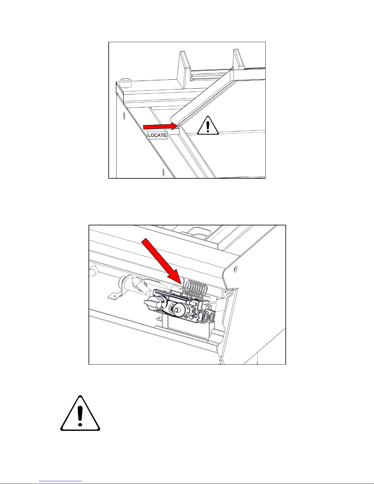
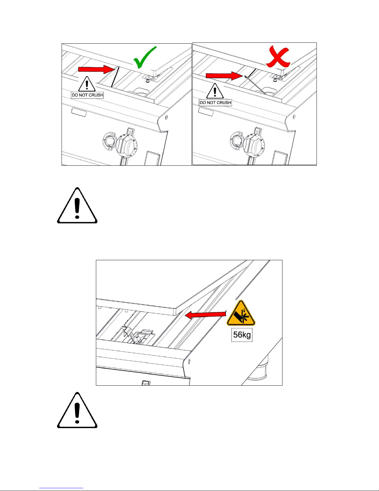
8.9.4 Replace the thermostat phial on to the plate and locate the plate as shown.
8.9.5 Ensure all excess capillary tube is located in the control panel area as shown.
DO NOT LEAVE EXCESS CAPILLARY TUBE INSIDE THE
BURNER BOX AREA.
Page 22
22
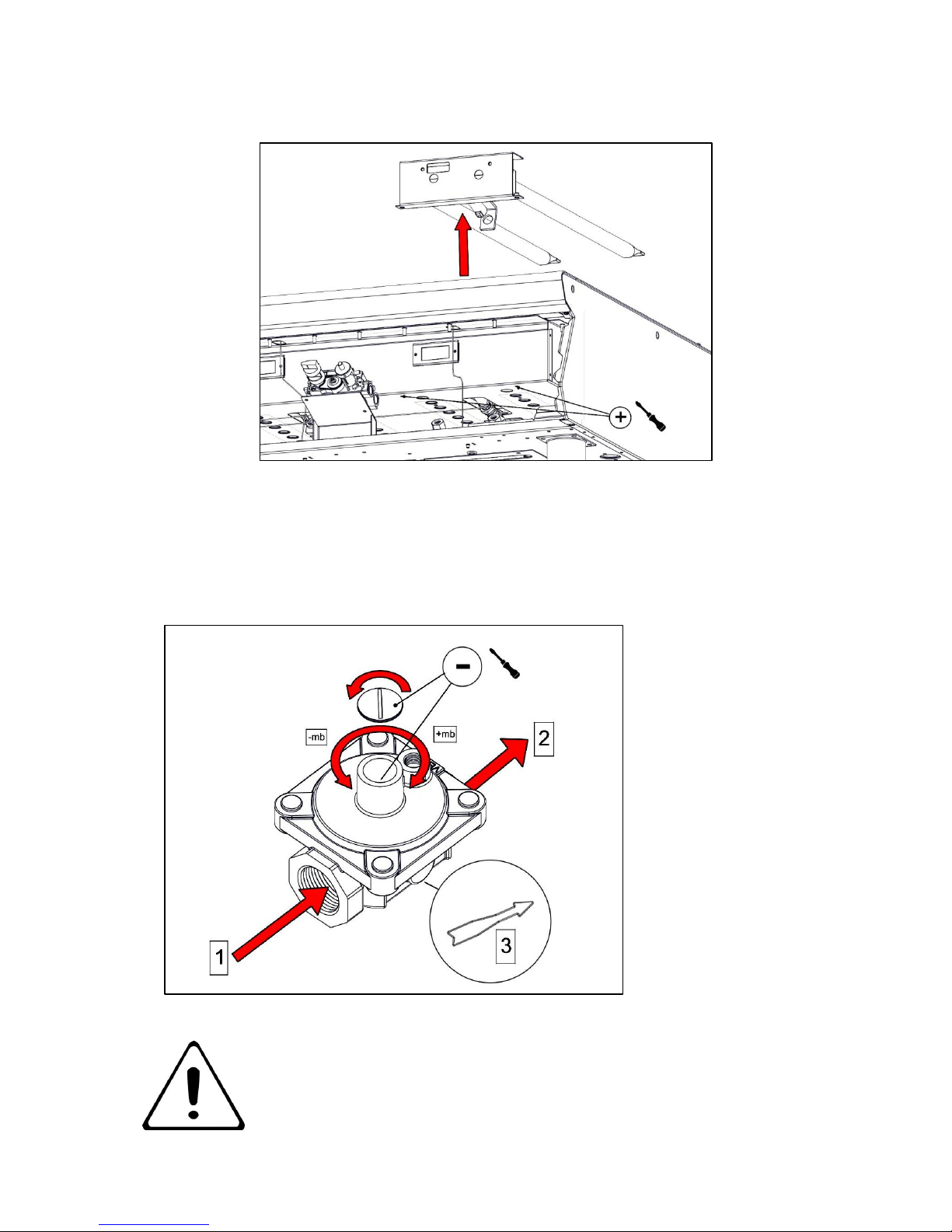
8.9.6 Lower the plate carefully ensuring the thermostat capillary tube does not get crushed.
DO NOT CRUSH THERMOSTAT CAPILLARY TUBE. ENSURE THE
TUBE GOES STRAIGHT DOWN THROUGH THE BURNER BOX
HOLE AS SHOWN ON THE LEFT. ENSURE IT DOES NOT BEND
INSIDE THE BURNER BOX AS SHOWN ON THE RIGHT.
RISK OF CRUSHING HANDS - REPLACE PLATE CAREFULLY.
Page 23
23
8.10 BURNER
8.10.1 Remove burner as shown.
8.11 GOVERNOR
8.11.1 This applies to G30 (50mb) models only.
GOVERNOR SUPPLIED IS MAINTENANCE FREE. ENSURE THE
BLUE DUST CAP COVERING THE VENT IS FITTED AND IN GOOD
CONDITION.
1 – Gas In
2 – Gas Out
3 – Direction of Flow
Page 24

24
9.0 FAULT FINDING
FAULT
POSSIBLE CAUSES
REMEDY
Pilot does not light.
No gas supply.
Restore supply.
Faulty spark igniter.
Test igniter button, lead
and electrode. Replace as
necessary.
Pilot does not stay lit.
Faulty thermocouple.
Check thermocouple is
tight and tip is in pilot
flame.
Main burner(s) does not
light.
Gas pressure too low.
Check pressure, adjust as
necessary.
Injector(s) blocked or
damaged.
Clear nozzle(s) or replace.
Burner ports blocked.
Clear ports or replace.
Gas tap(s) seized or
blocked.
Clear or replace as
necessary.
Slow/Poor heating.
Valve pressure wrong.
Check pressure and adjust
if necessary.
Burner ports blocked.
Check burner and clean if
dirty.
Low mains gas pressure.
Check with gas supplier.
Gas supply isolated/off.
Restore supply.
Check with gas supplier.
Page 25

25
10.0 SPARE PARTS
Main spare parts:
Gas Valve
Pilot Assembly
Thermocouple
Fat Jug
Control Knob
When ordering spares, quote the following:
Model Number
Serial number
Gas Type
This information is found on data plate on front panel. (See section 1.0)
Visit our website for further spares information.
11.0 SERVICE INFORMATION
It is recommended to have a maintenance contract with a local service provider.
SERVICELINE CONTACT:
(UK only)
Phone: +441438 363 000
Warranty Policy Shortlist
For our warranty policy please go to www.falconfoodservice.com
 Loading...