

Falcon G9440, G9490, G94120, G9460, F900 SERIES User, Installation And Servicing Instructions

1
F900 SERIES
User, installation and servicing instructions
GAS CHARGRILL
G9440, G9460, G9490, G94120
Read these instructions before use
T100873
DATE PURCHASED:
MODEL NUMBER:
SERIAL NUMBER:
DEALER:
SERVICE PROVIDER:
REV. 4
Published: 23/08/2016

2
Falcon Foodservice Equipment
HEAD OFFICE
Wallace View, Hillfoots Road, Stirling. FK9 5PY. Scotland.
WEEE Directive Registration No. WEE/DC0059TT/PRO
At end of appliance life, dispose of appliance and any replacement parts in a safe
manner, via a licensed waste handler. Appliances are designed to be dismantled
easily and recycling of all material is encouraged whenever practicable.
Dear Customer,
Thank you for choosing Falcon Foodservice Equipment.
This manual can be downloaded from www.falconfoodservice.com or scan
here.
IMPORTANT: Please keep this manual for future reference.

3
SYMBOLS
• SPANNER • SCREWDRIVER • COOKING OIL • GREASE
• SPARK IGNITION • FLAME • WARNING • VIEWPORT
• ALLEN KEY •IGNITER

4
These instructions are only valid if the country code appears on the
appliance. If the code does not appear on the appliance, refer to the
technical instructions for adapting the appliance to the conditions for use
in that country.
Installation must meet national or local regulations. Attention must be paid
to: gas safety (installation & use) regulations, health and safety at work act,
local and national building regulations, fire precautions act.
To prevent shocks, all appliances must be earthed.
This equipment is for professional use only and must be used by qualified
persons.
The installer must instruct the responsible person(s) of the correct
operation and maintenance of the appliance.
Only competent persons are allowed to service or convert the appliance to
another gas type.
Gas appliances must have a stop cock fitted in the supply pipe work. The
user must be familiar with the location and operation of this device in order
to turn off the supply of gas in the event of an emergency.
Unless otherwise stated, parts which have been protected by the
manufacturer must not be adjusted by the installer.
Take care when moving an appliance fitted with castors.
The appliance must be serviced regularly by a qualified person.
Service intervals should be agreed with the service provider.
This appliance may be discolored due to testing.

5
CONTENTS
1.0 APPLIANCE INFORMATION ..................................................................................... 6
2.0 OPERATION .............................................................................................................. 7
2.1 COMPONENT PARTS ............................................................................................ 7
2.2 CONTROLS ............................................................................................................ 7
2.3 USING THE APPLIANCE ........................................................................................ 8
3.0 CLEANING AND MAINTENANCE .............................................................................. 9
4.0 SPECIFICATION ...................................................................................................... 10
5.0 DIMENSIONS / CONNECTION LOCATIONS ........................................................... 12
6.0 INSTALLATION ................................ ................................................................ ........ 13
6.1 SITING / CLEARANCES ....................................................................................... 13
6.2 VENTILATION ....................................................................................................... 13
6.3 GAS SUPPLY & CONNECTION ........................................................................... 14
6.4 ASSEMBLY ........................................................................................................... 15
6.5 COMMISSIONING ................................................................................................ 15
6.6 SUITING ............................................................................................................... 16
7 CONVERSION ............................................................................................................. 18
7.4 GAS CONVERSION CHECK LIST ........................................................................ 18
8 SERVICING ................................................................................................................. 19
8.1 BURNERS ............................................................................................................. 19
8.2 INJECTORS .......................................................................................................... 21
8.3 CONTROL PANEL ................................................................................................ 22
8.4 PILOT ASSEMBLY ................................................................................................ 22
8.5 GAS VALVE .......................................................................................................... 23
8.6 GOVERNOR ......................................................................................................... 24
9 FAULT FINDING .......................................................................................................... 25
10 SPARE PARTS ........................................................................................................ 26
11 SERVICE INFORMATION ........................................................................................ 26
6
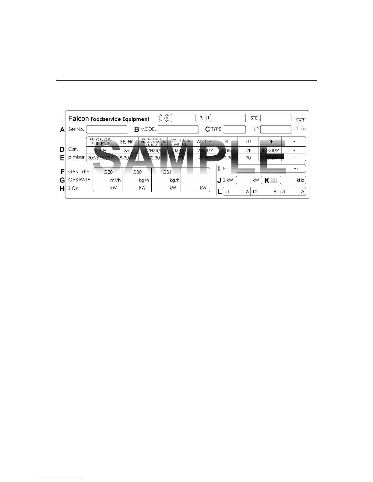
1.0 APPLIANCE INFORMATION
This appliance has been CE-marked on the basis of compliance with the relevant EU
directives for the heat inputs, gas pressures and voltages stated on the data plate.
A - Serial No
B - Model No
C - Flue Type
D - Gas Category
E - Gas Pressure
F - Gas Type
G - Gas Rate
H - Total Heat Input
I - Electrical Rating
J - Total Electrical Power
K - Magnetic Field Frequency
L - Electrical Phase Loading
7
2.0 OPERATION
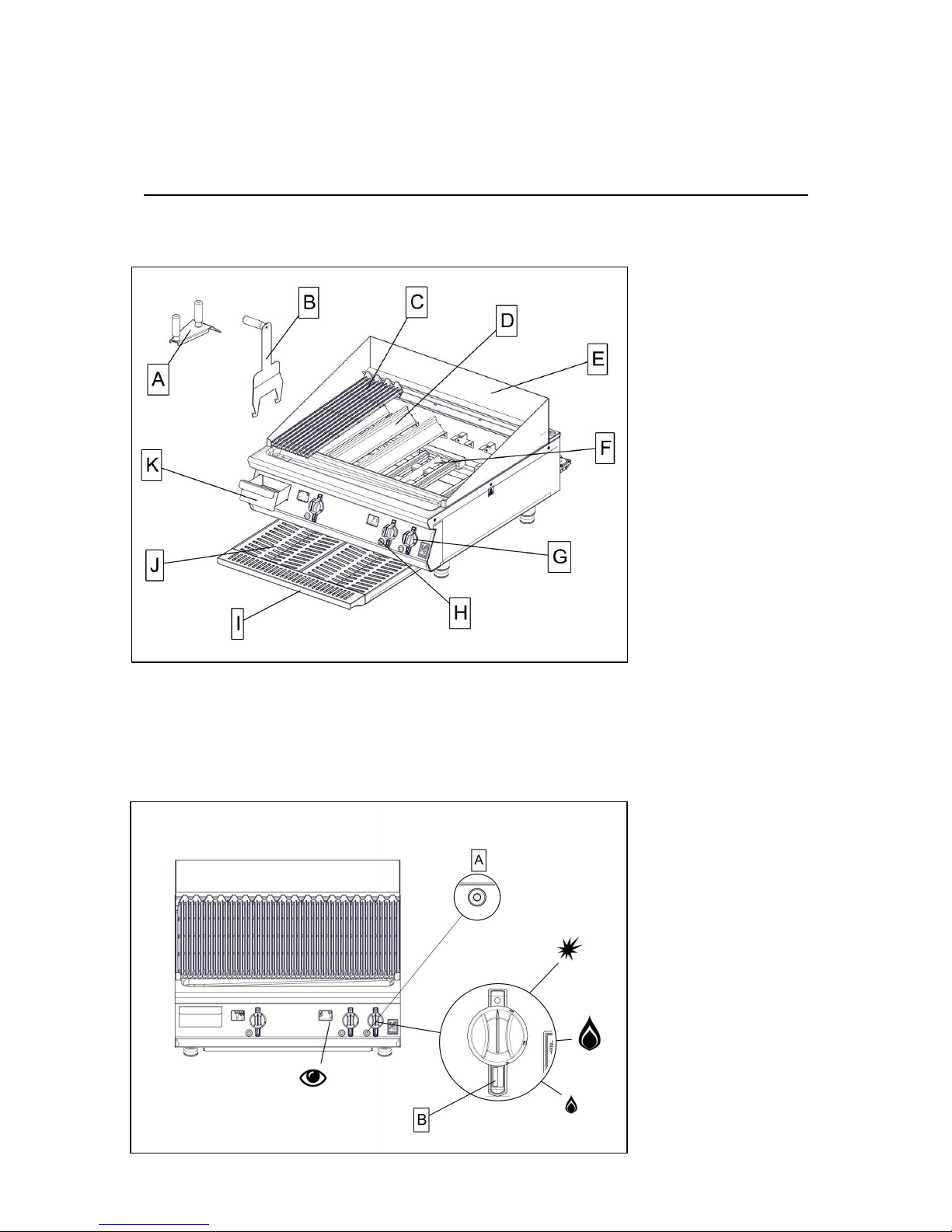
2.1 COMPONENT PARTS
A – Scraper
B – Lifting Tool
C – Brander Bar
D – Burner Baffle
E – Splashguard
F – Burner
G – Control Knob
H – Spark Igniter
I – Drip Tray
J* – Deflector
K – Fat Jug
* Not required in G9440.
2.2 CONTROLS
A – Spark Igniter
B – Zone Indicator
8
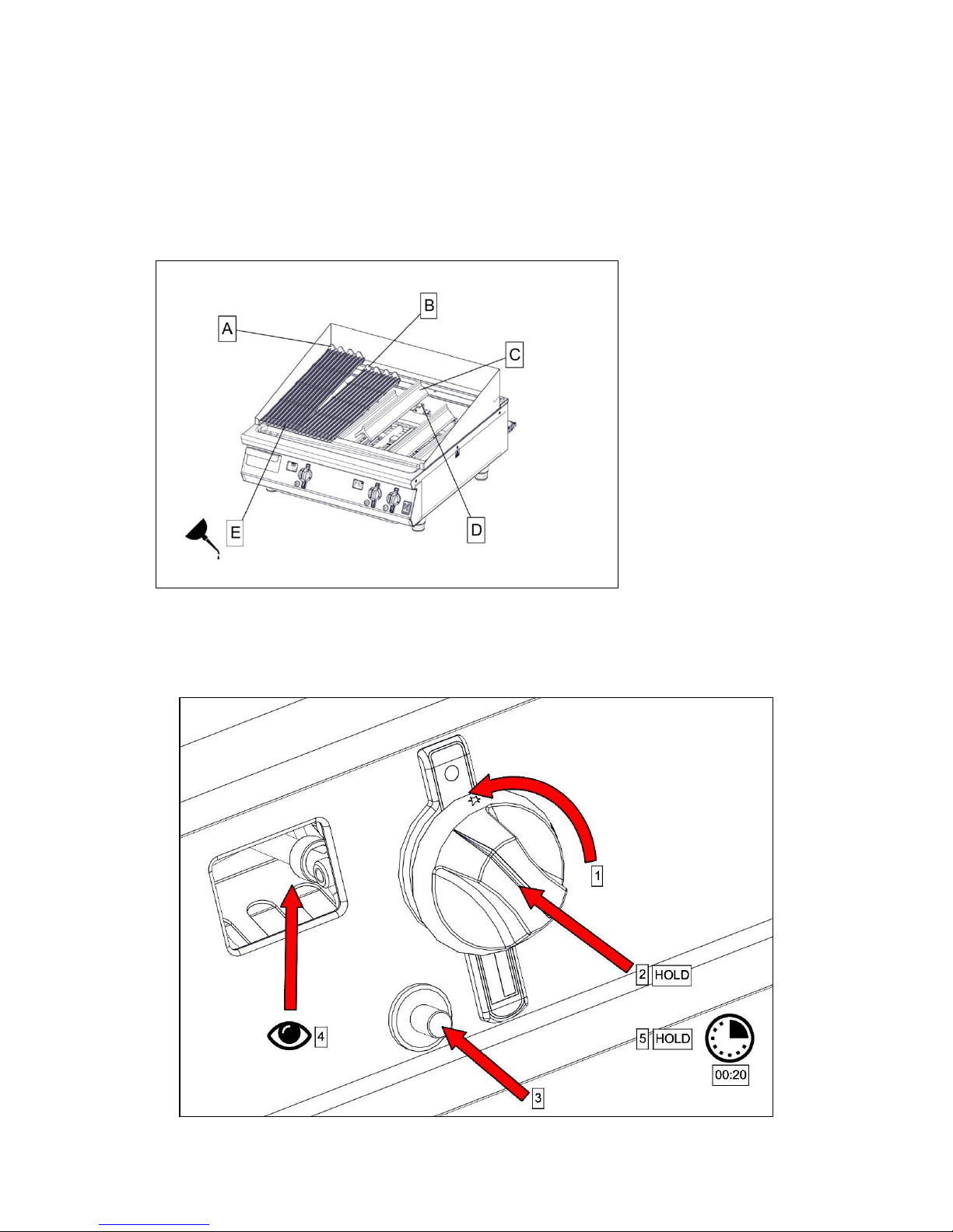
2.3 USING THE APPLIANCE
2.3.1 Before use, clean the appliance inside and out. See section 3.
2.3.2 Position burner baffles and brander bars correctly.
A - High position
B – Low position
C – Burner Baffle
D – Baffle support
E– Lightly oil bars
2.3.3 Fill about a 1/3 of the drip tray with water.
2.3.4 Ignite the burners as shown. Push the knob in to turn.
 Loading...