

Page 1

1
F900 SERIES
User, installation and servicing instructions
FRYER
G9341, G9341F
Read these instructions before use
T100889
DRAFT REV 9
Published: 08.09.16
DATE PURCHASED:
MODEL NUMBER:
SERIAL NUMBER:
DEALER:
SERVICE PROVIDER:
Page 2
2
Falcon Foodservice Equipment
HEAD OFFICE
Wallace View, Hill foots Road, Stirling. FK9 5PY. Scotland.
WEEE Directive Registration No. WEEE/DC0059TT/PRO
At end of appliance life, dispose of appliance and any replacement parts in a safe
manner, via a licensed waste handler. Appliances are designed to be dismantled
easily and recycling of all material is encouraged whenever practicable.
Dear Customer,
Thank you for choosing Falcon Foodservice Equipment.
This manual can be downloaded from www.falconfoodservice.com or scan
here
IMPORTANT: Please keep this manual for future reference.
Page 3

3
SYMBOLS•
• SPANNER • SCREWDRIVER • COOKING OIL • GREASE
• SPARK IGNITION • FLAME • WARNING • VIEWPORT
• ALLEN KEY • IGNITER
Page 4

4
This appliance may be discoloured due to testing.
These instructions are only valid if the country code appears on the
appliance. If the code does not appear on the appliance, refer to the
technical instructions for adapting the appliance to the conditions for
use in that country.
Installation must meet national or local regulations. Attention must be
paid to: gas safety (installation & use) regulations, health and safety at
work act, local and national building regulations, fire precautions act.
Gas appliances must have a stop cock fitted in the supply pipe work.
The user must be familiar with the location and operation of this device
in order to turn off the supply of gas in the event of an emergency.
This appliance has been CE- marked o the basis of compliance with the
Low voltage & EMC Directives for voltages stated on the Data Plates.
To prevent shocks, all appliances must be earth bonded.
The unit is fitted with equipotential connection at the rear on the base.
We recommend supplementary electrical protection with the use of a
residual current device. (RCD).
This equipment is for professional use only and must be used by
qualified persons.
The installer must instruct the responsible person(s) of the correct
operation and maintenance of the appliance.
Unless otherwise stated, parts which have been protected by the
manufacturer must not be adjusted by the installer.
Take care when moving an appliance fitted with castors.
The appliance must be serviced regularly by a qualified person. Service
intervals should be agreed with the service provider.
Check that no damage has occurred to the appliance or supply cord
during transit. If damage has occurred, do not use the appliance.
Ensure supply cord is routed free from appliance to avoid damage.
Only competent persons are allowed to service or convert the appliance
to another gas type.
Installation, periodic testing, repair & fixed wired connections should
only be undertaken by a competent electrician.
The appliance has been designed and approved to use Falcon Kick
plates: Non Falcon kick plates could potentially adversely affect the
performance of the appliance by restricting the air to the appliance.
Page 5

5
CONTENTS
1 APPLIANCE INFORMATION ......................................................................................... 6
2 OPERATION .................................................................................................................. 7
2.1 COMPONENT PARTS ............................................................................................ 7
2.2 CONTROLS G9341/F ............................................................................................. 8
2.3 USING THE APPLIANCES ..................................................................................... 9
3 CLEANING AND MAINTENANCE ............................................................................... 11
4 SPECIFICATION ......................................................................................................... 12
4.1 TABLE A ............................................................................................................... 12
4.2 TABLE B – G20 .................................................................................................... 13
4.3 TABLE B – G30/G31 ............................................................................................. 13
5 DIMENSIONS / CONNECTION LOCATIONS .............................................................. 14
6 INSTALLATION ........................................................................................................... 15
6.1 SITING / CLEARANCES ....................................................................................... 15
6.2 VENTILATION ...................................................................................................... 16
6.3 GAS /ELECTRIC SUPPLY & CONNECTION ........................................................ 16
6.4 ASSEMBLY .......................................................................................................... 17
6.5 COMMISSIONING ................................................................................................ 18
6.6 SUITING .............................................................................................................. 20
7 CONVERSION .............................................................................................................. 22
7.1 GAS CONVERSION CHECK LIST ....................................................................... 22
8 SERVICING .................................................................................................................. 24
8.1 DOOR ................................................................................................................... 24
8.2 CONTROL PANEL ............................................................................................... 24
8.3 FASTRON CONTROLLER & NEONS ................................................................... 25
8.4 SWITCH PANEL ................................................................................................ ... 26
8.5 SWITCH & NEON REMOVAL ............................................................................... 27
8.6 ACCESS TO SPARK BOX .................................................................................... 28
8.7 SIT GAS REGULATOR ACCESS ......................................................................... 29
8.8 PUMP & TIMER REMOVAL .................................................................................. 29
8.9 PUMP & TIMER REMOVAL .................................................................................. 30
8.10 TIMER PUMP SETTINGS ..................................................................................... 30
9 ACCESSORIES ........................................................................................................... 31
9.1 SPLASH GUARD.. ................................................................................................ 31
9.2 DRAIN HOSE.. ..................................................................................................... 31
10 FAULT FINDING........................................................................................................... 32
11 SPARE PARTS. ........................................................................................................... 33
12 SERVICE INFORMATION. ........................................................................................... 33
Page 6
6
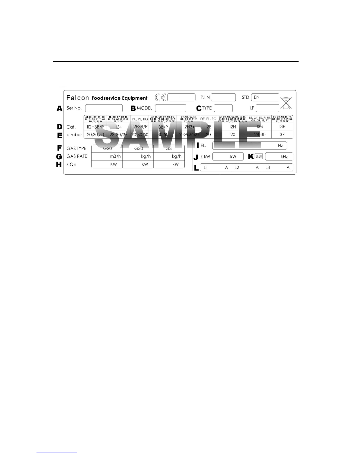
1 APPLIANCE INFORMATION
This appliance has been CE-marked on the basis of compliance with the relevant EU
directives for the heat inputs, gas pressures and voltages stated on the data plate.
A - Serial No
B - Model No
C - Flue Type
D - Gas Category
E - Gas Pressure
F - Gas Type
G - Gas Rate
H - Total Heat Input
I - Electrical Rating
J - Total Electrical Power
K - Magnetic Field Frequency
L - Electrical Phase Loading
Page 7

7
2 OPERATION
2.1 COMPONENT PARTS
FRYER
A – TEMPERATURE CONTROL F – DRAIN VALVE
B – POWER NEON (RED) G – OIL BUCKET
C – HEAT DEMAND NEON (AMBER) H – SAFETY LIMITER
D – BURNER RESET I – PUMP SWITCH
E – Power ON/OFF RESET J – QUICK RELEASE RETURN PIPE
Page 8
8
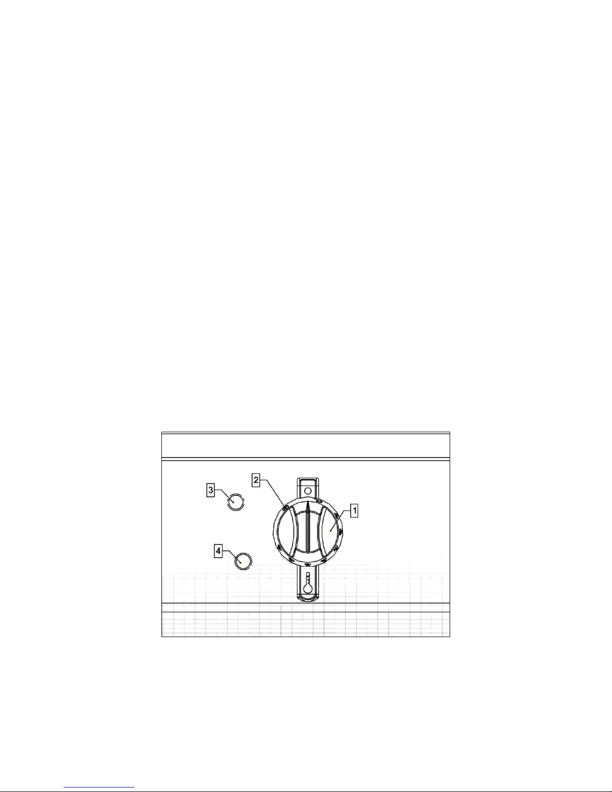
2.2 CONTROLS G9341/F
2.2.1 ON/OFF Temperature control knob
Temperature Selection (140 -190°C) (Unit off when control is in position
Indicated).
2.2.2 Fat Melting Position
2.2.3 Power on Indicator
2.2.4 Heat Demand Indicator
Illuminates when the thermostat demands heat, i.e. oil temperature is
more than
5⁰ C below temperature setting.
Extinguishes when desired temperature is reached.
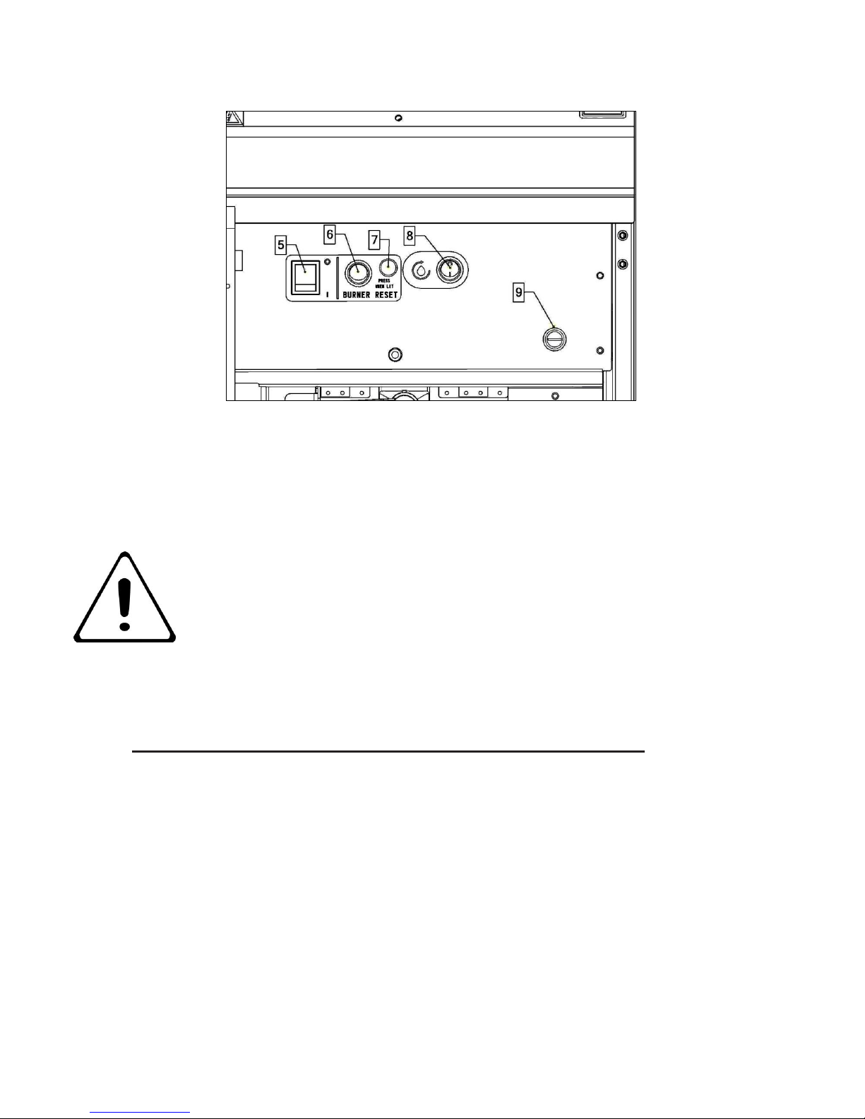
2.2.5 Burner and Temperature Controls on/off Switch
Cuts power and temperature controls
2.2.6 Burner Lock-out Switch
(Reset burner for further lighting attempts when burner lockout indicator is
Illuminated).
2.2.7 Burner lock-out Indicator (Indicates flame failure).
2.2.8 Filtration Pump Switch (G9341F only)
Energizes filtration pump when burner is in OFF (O) position.
2.2.9 Temperature Safety Limiter Reset Button
Located inside red recess below black cover.
Page 9
9
2.3 USING THE APPLIANCES
2.3.1 Always clean the appliance before use. See section 3.0
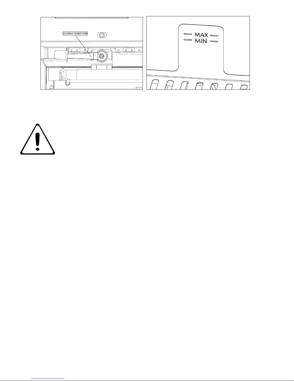
2.3.2 Ensure drain valve is closed. Fill pan with cooking medium to -MIN- (maximum cold
fill mark). Do not fill medium past MAX level mark.
MIN- Level Mark: Medium should NEVER be allowed to drop below this
mark. Should this occur, top up immediately or switch fryer OFF.
CAUTION: SUITABLE PROTECTIVE CLOTHING
MUST BE WORN when topping up whilst fat in fryer is hot.
Medium and Foodstuffs
Food will increase in volume during cooking - follow these rules:
NEVER ADD WATER TO FRYING MEDIUM AT ANY TIME!
Page 10
10
2.3.3 Switch power on 2.2.5
2.3.4 Set temperature 2.2.1. If solid fat is to be used, Ensure FAT MELT CYCLE is
selected for this process 2.2.2
Medium should not be overheated as this will increase the risk of fire.
Note: NEVER leave a working unit unattended.
Note: Fryer is fitted with a thermal safety device. This will stop heating of
medium if it becomes overheated. This appliance will always fail
safe.
2.3.5 Fryer maximum basket loading.
Pre-blanched chilled fries– 2 x 1.5kg baskets.
Frozen fries – 2 x 1.2kg baskets
2.3.6 Turn burner off. Set temperature control 2.2.1 as above and set 2.2.5 to
Off.
2.3.7 Filtration Instructions.
After filtering wait 30 seconds before removing bucket.
Switch burner off by means of burner ON/OFF Switch
Wait 15/20 mins to allow oil to cool
Lift safety drain cover
Open drain valve
Allow oil to drain from pan
Switch to filter pump
Cycle oil until pan is clear of debris
Close drain valve and allow pan to fill
Continue as indicated in lighting instructions
Page 11
11
3 CLEANING AND MAINTENANCE
3.1.1 Turn off and cool down.
3.1.2 All surfaces are easier to clean if spillage is removed before it becomes burnt on,
cleaned daily.
THE APPLIANCE MUST NOT BE STEAM CLEANED. DO NOT USE ACID OR
HALOGEN-BASED (e.g. chlorine) DESCALING LIQUIDS, FLAMMABLE
LIQUIDS, CLEANING AIDS OR CLEANING POWDERS.
Stainless Steel Surfaces
It should be noted that certain scouring pads including nylon types can easily mark
stainless steel. Care should be exercised during cleaning process.
When rubbing stainless steel with a cloth, always rub in grain direction.
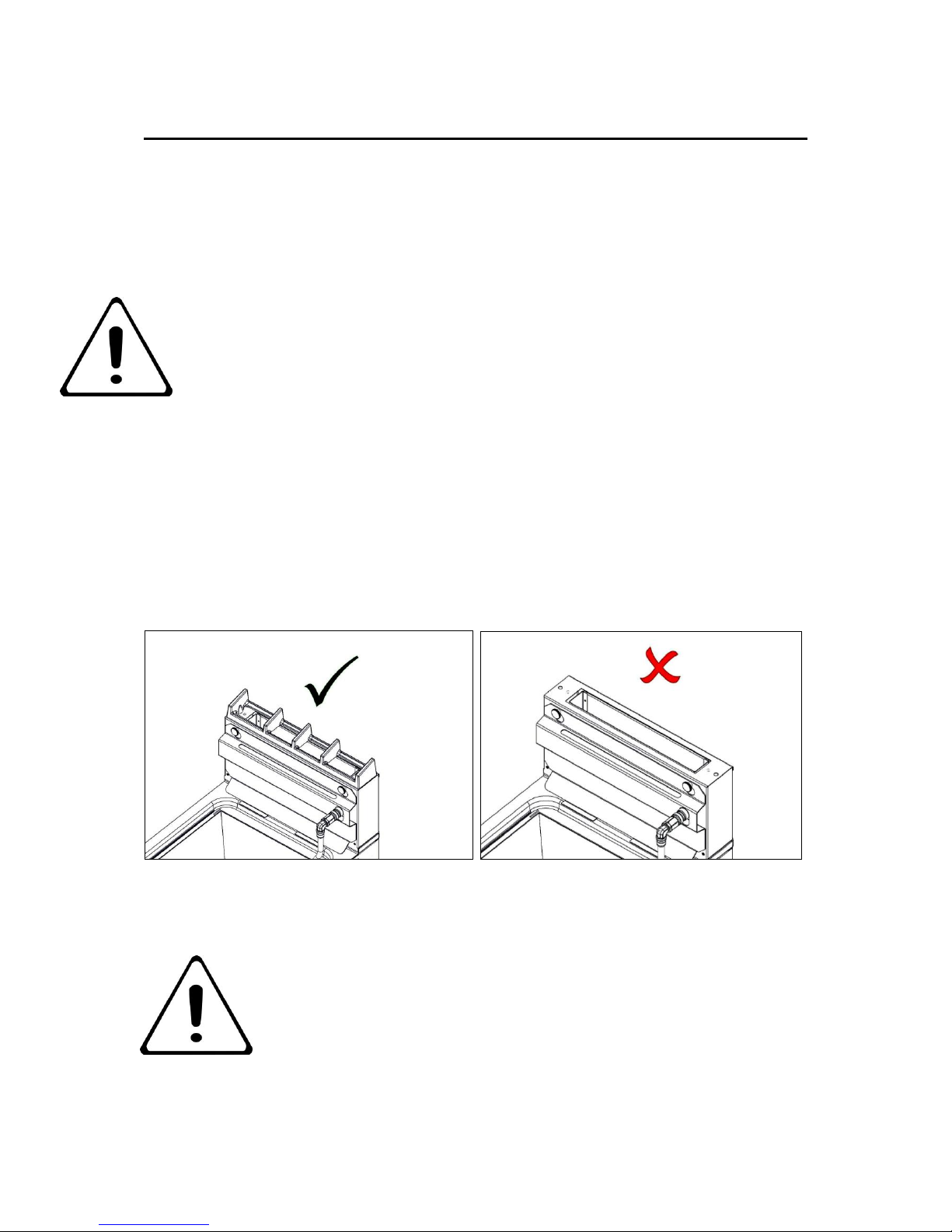
3.1.3 The flue capper can be removed for cleaning but must be replaced for use
FAILURE DUE TO LACK OF PROPER CLEANING IS NOT
COVERED BY WARRANTY
Page 12
12
4 SPECIFICATION
4.1 TABLE A
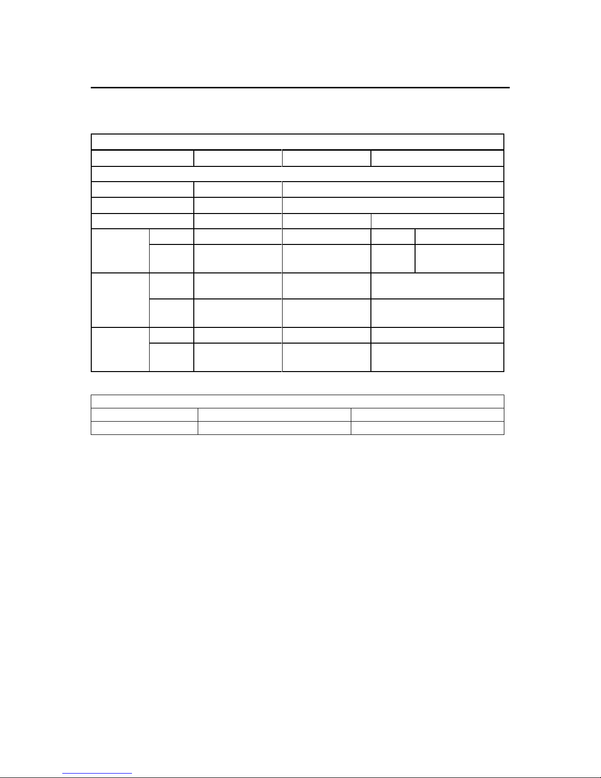
TABLE A
G20
G31
G30
G9341/F Fryer
Injector
Ø2.7
Ø1.7
Pilot Injectors
Polidora G31.2
Polidora G25
Low Rate Screw
N/A
Supply
Pressure
mbar
20
37
29
50
Inches
w.g
8.3
14.9
11.6
20.
Operating
Pressure
mbar
14
34.5
29
Inches
w.g
5.6
13.9
11.6
Low rate
Pressure
mbar
N/A
N/A
N/A
Inches
w.g
N/A
N/A
N/A
TABLE A -1
Rated Voltage
Rated Current
G9341/F
230V
3.55 amps
Page 13
13
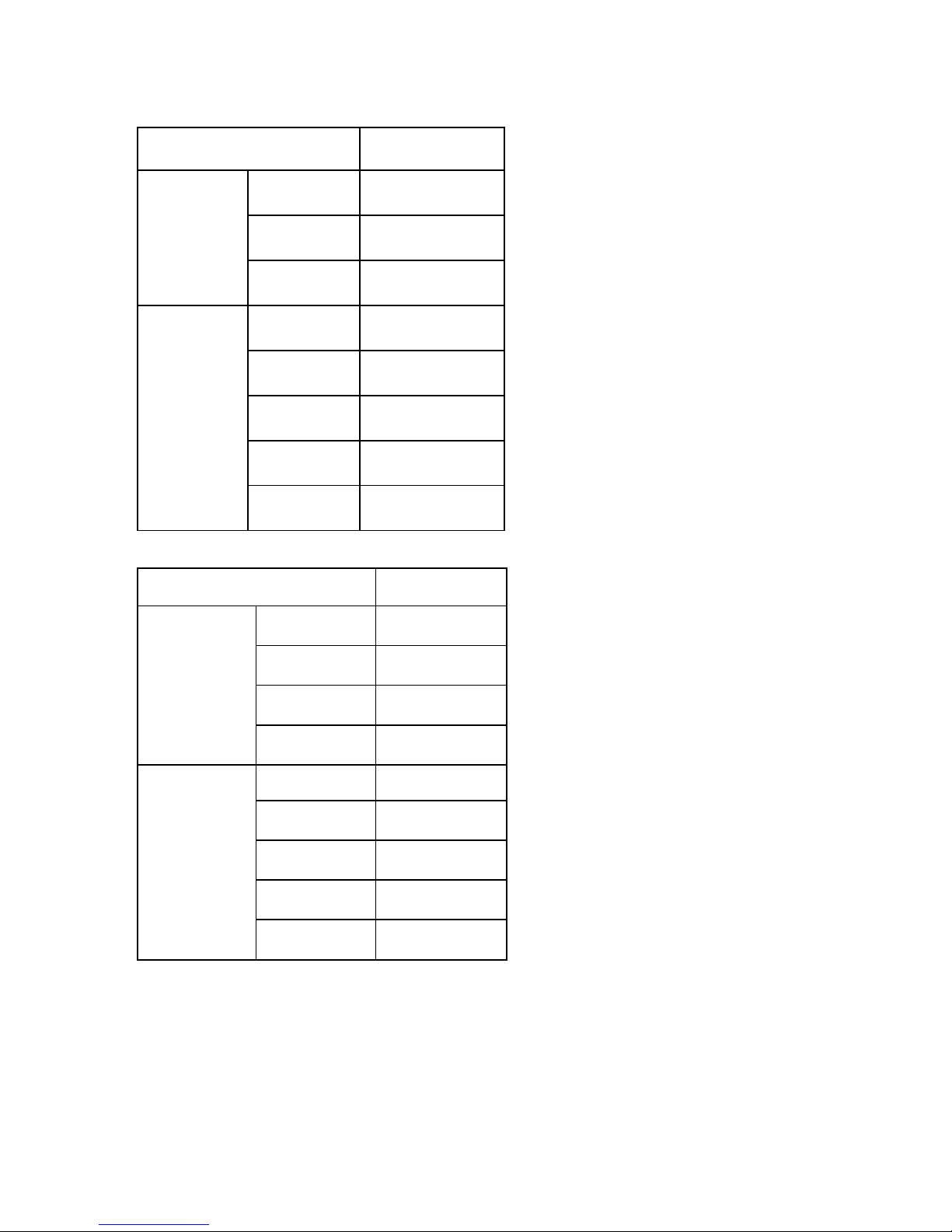
4.2 TABLE B – G20
G9341/F
Total Input
kW
net
23
Btu/hr
gross
86,348
m3/H
net
2.26
Test Limits
Max kW
24.15
Min KW
21.85
Max Btu/hr
90,666
Min Btu/hr
82,031
m3/H
net
4.3 TABLE B – G30/G31
G9341/F
Total Input
kW
net
22
Btu/hr
gross
82,594
kg/h G30
net
1.599
kg/h G31
net
1.573
Test Limits
Max kW
23.1
Min kW
20.9
Max Btu/hr
86,724
Min Btu/hr
78,464
Page 14

14
5 DIMENSIONS / CONNECTION LOCATIONS
G9341/F UNIT WEIGHT 94 Kg
Page 15
15
6 INSTALLATION
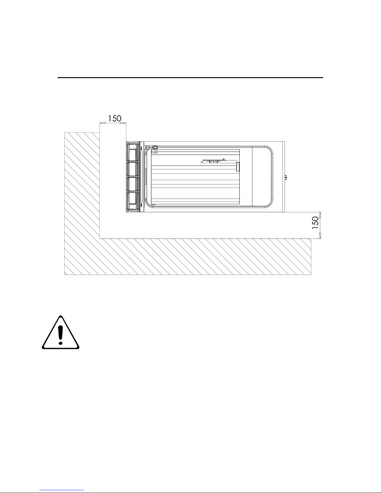
6.1 SITING / CLEARANCES
CAUTION: WALLS CLOSER THAN 150mm TO THE APPLIANCE MUST BE
NON COMBUSTABLE. IF SUITING THE NECESSARY CLEARANCES TO ANY
CUMBUSTIBLE WALL MUST BE THE LARGEST FIGURE GIVEN FOR
INDIVIDUAL APPLIANCES INSTRUCTIONS.
Page 16
16
6.2 VENTILATION
The appliances must to be installed with sufficient ventilation to prevent the occurrence of
unacceptable concentrations of substances harmful to health in the room in which they are
installed. Installer must consult any additional local / national regulations.
COMBUSTION AIR REQUIREMENTS
G9341
G9341F
G20
21m³h
21m³h
G30
20m³h
20m³h
G31
19m³h
19m³h
6.3 GAS /ELECTRIC SUPPLY & CONNECTION
6.3.1 A qualified installer should be called to install the appliance and if necessary to
convert it for other gases.
Installation pipe work should be fitted in accordance with local / national standards. The pipe
work must not be smaller than unit gas inlet connection, i.e. Rp¾ (¾” B.S.P.). If using
flexible hosing, the length must not exceed 1.5m. An isolating valve must be located close by
for shut-down during an emergency or servicing.
If flexible hose is used, it shall comply with national requirements. These must be
periodically examined and replaced as necessary. If a retention chain is required then attach
the fixing on the rear top panel.
The unit is equipped with a 3-core flexible cord with standard 3 pin plug fitted with a 13A
fuse. A regular 13A socket outlet can be used.
If supply is provided through a distribution fuse box, it must be via a fuse with a maximum
rating of 13A.
In the event of mains cable being replaced, any new cable should comply with 60245 IEC 57
designations. (H05 RN - F).
Page 17
17
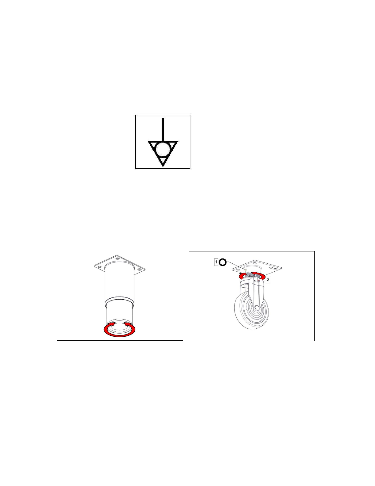
6.3.2 This appliance is also provided with a terminal for connection of an external
equipotential conductor. This terminal is in effective electrical contact with all fixed
exposed metal parts of the appliance, and shall allow the connection of conductor
having a nominal cross-section area of up to 10mm².
It is located at the rear of the unit and identified by the following label and must only
be used for bonding purposes.
6.4 ASSEMBLY
6.4.1 Position appliance and level using feet or castor adjusters as shown below. Fit anti tilt
device.
Page 18
18
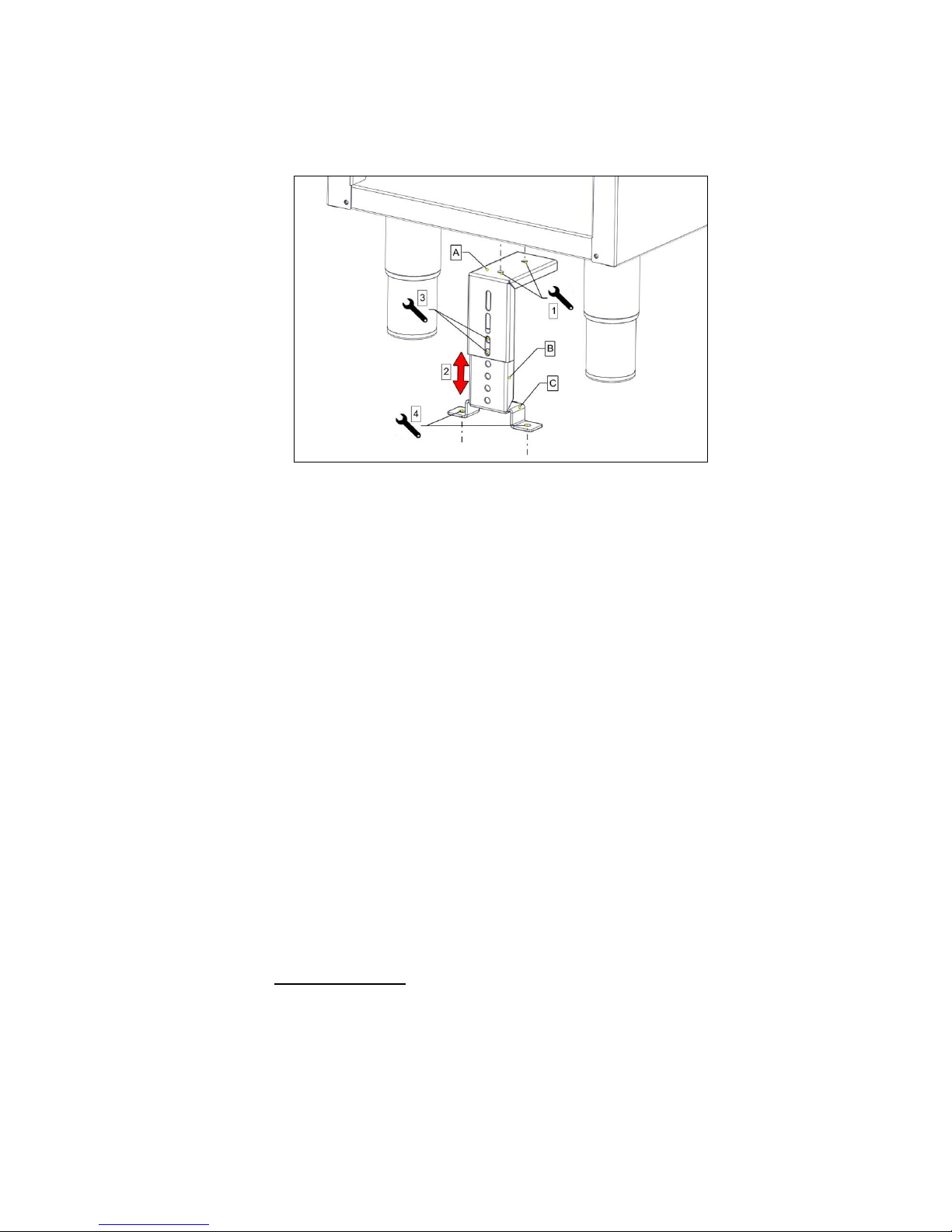
Appliances with castors should be fitted with accessories supplied according to
separate instructions provided.
Connect appliance to gas supply and test for gas tightness as stated in 7.4.
6.5 COMMISSIONING
6.5.1 With gas supply still shut off, turn on electrical mains supply.
6.5.2 Open door and press temperature limit thermostat reset button (red) refer to section
2.6. Set burner switch to ‘I’ (on position)
6.5.3 Turn control knob to desired temperature (180°) and heat demand indicator will
illuminate.
6.5.4 Fryer ignition sequence will commence and spark may be heard before unit locks out
Note: Ignition system will attempt a second sequence, 14 seconds after completion
of first try if no flame is detected during first attempt. (Unit will only lock out after 2nd
attempt).
6.5.5 Neon next to burner switch inside door will illuminate to indicate lockout has occurred
and that no burner flame is present. G9341 / G9341F.
6.5.6 Turn gas supply on.
6.5.7 Press lockout reset switch. (Lock out neon will extinguish).
6.5.8 Burner will ignite and heat indicator will illuminate to signify that burner is on.
If lockout should occur, repeat Steps 8 -9 until air is bled from supply and burner
lights.
6.5.9 When burner flame is established, check for gas leaks. Care should be taken
because MAINS VOLTAGE is present. Isolate after gas checks.
Page 19

19
TEMPERATURE LIMIT THERMOSTAT
The unit is equipped with an additional temperature limit thermostat, independent of main
controller.
In the case of operating thermostat failure, allowing oil temperature to rise above
predetermined legislation safe zone (230°C),a limit device will activate and cut power to
controller. It will also stop the flow of gas to burner, refer to 2.2.
a) Turn burner and temperature controls ON/OFF knob to OFF position.
b) Allow oil to cool below 180°C
c) Reset red button on limit thermostat with a pen or similar item, refer to 2.2.9.
d) Turn burner and temperature controls ON/OFF knob to ON position.
e) Re-select temperature.
f) If limit thermostat reactivates carry out fault finding on temperature control circuitry.
PLEASE FILL OUT THE INFORMATION TABLE ON THE FRONT
COVER AFTER COMMISSIONING.
Page 20
20
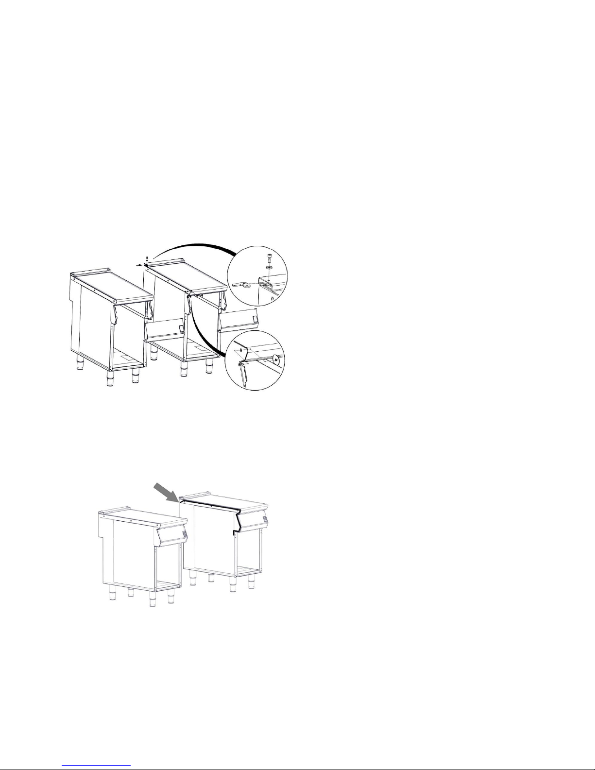
6.6 SUITING
“Patent pending, application no. GB 1511389.7”
6.6.1 Before leveling and suiting units ensure the units are fully built, including all
accessories and castings.
6.6.2 Undo the 4 fixing screws on the control panel and remove.
6.6.3 Remove the hob rear infill and replace with rear suiting plate and fixings.
6.6.4 Remove the front side panel countersunk screw and suiting plate.
NOTE: The DLS system is designed to give a quick and easy suiting solution. If
you require an improved seal between appliances we recommend you
use, a food grade, high temperature silicon sealant. This can be
supplied by Falcon part no – 523400021
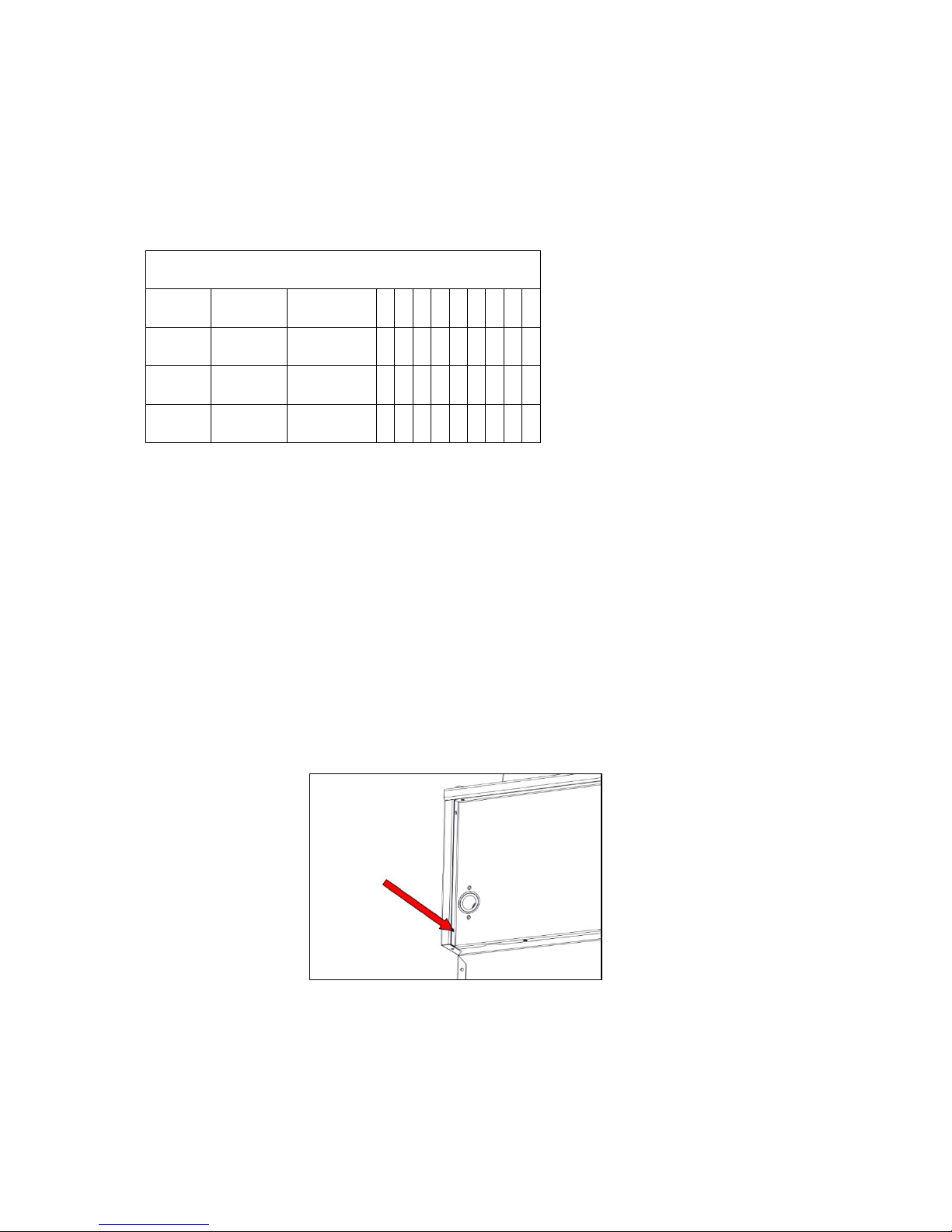
6.6.5 Run a bead of silicon 5mm from profile edge as highlighted below.
Fig. 1
Page 21
21
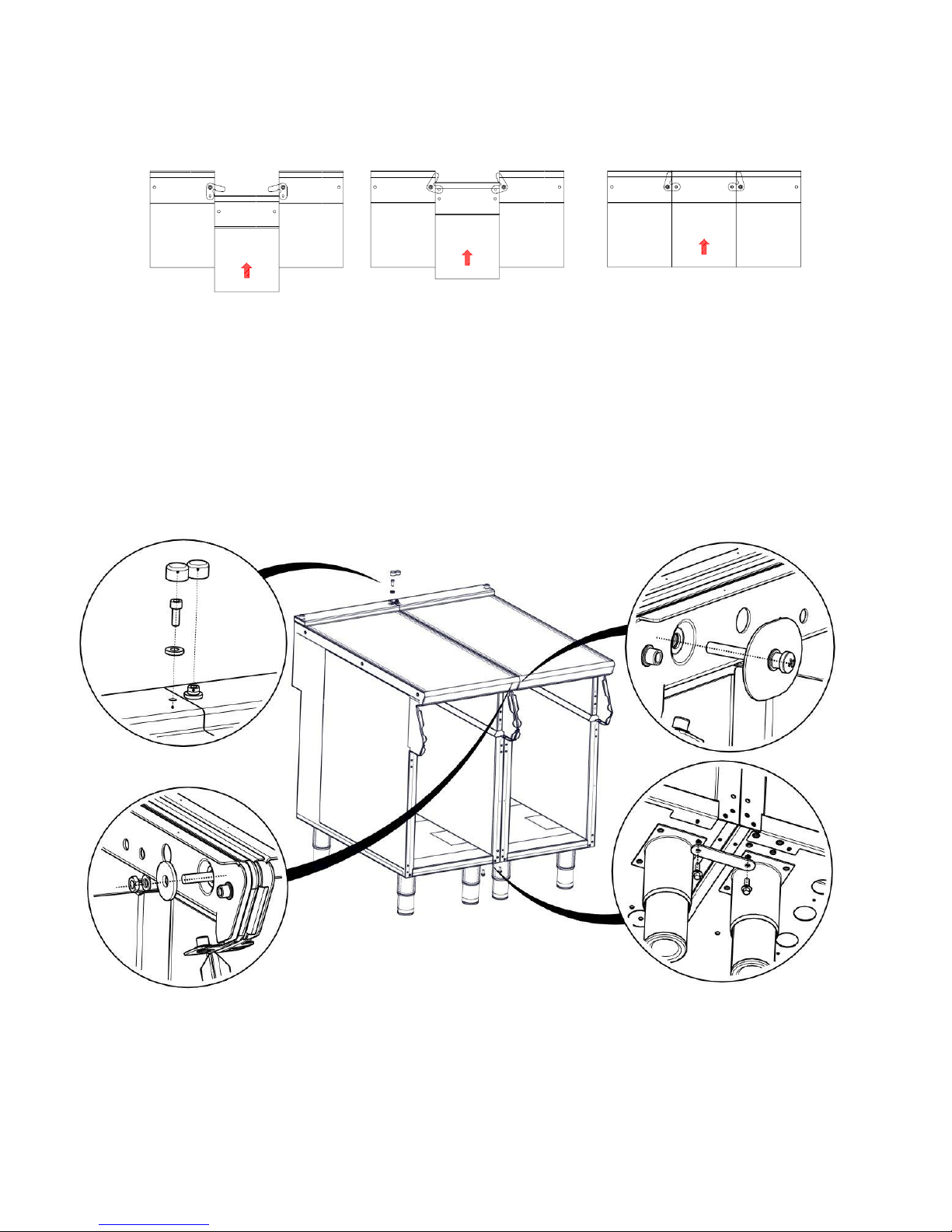
6.6.6 Slide suited units into position.
6.6.7 (A) Right hand unit: Screw the M5 x 40 screw (supplied in the kit) into one of the
suiting plates as shown and then insert through the front fixing holes of both units.
6.6.8 (B) Left hand unit: Slide the penny and lock washer on to the screw and secure using
the M5 nut.
6.6.9 (C) Remove the front bolts from feet, insert base tie plate and secure the bolts back
into position.
6.6.10 (D) Replace fixings on the rear hob and tighten screw caps into position.
6.6.11 Replace control panel.
A B C
D
Page 22
22
7 CONVERSION
BEFORE INSPECTION, SERVICING OR CONVERSION, TURN OFF
GAS AND ELECRTIC AT ISOLATORS.
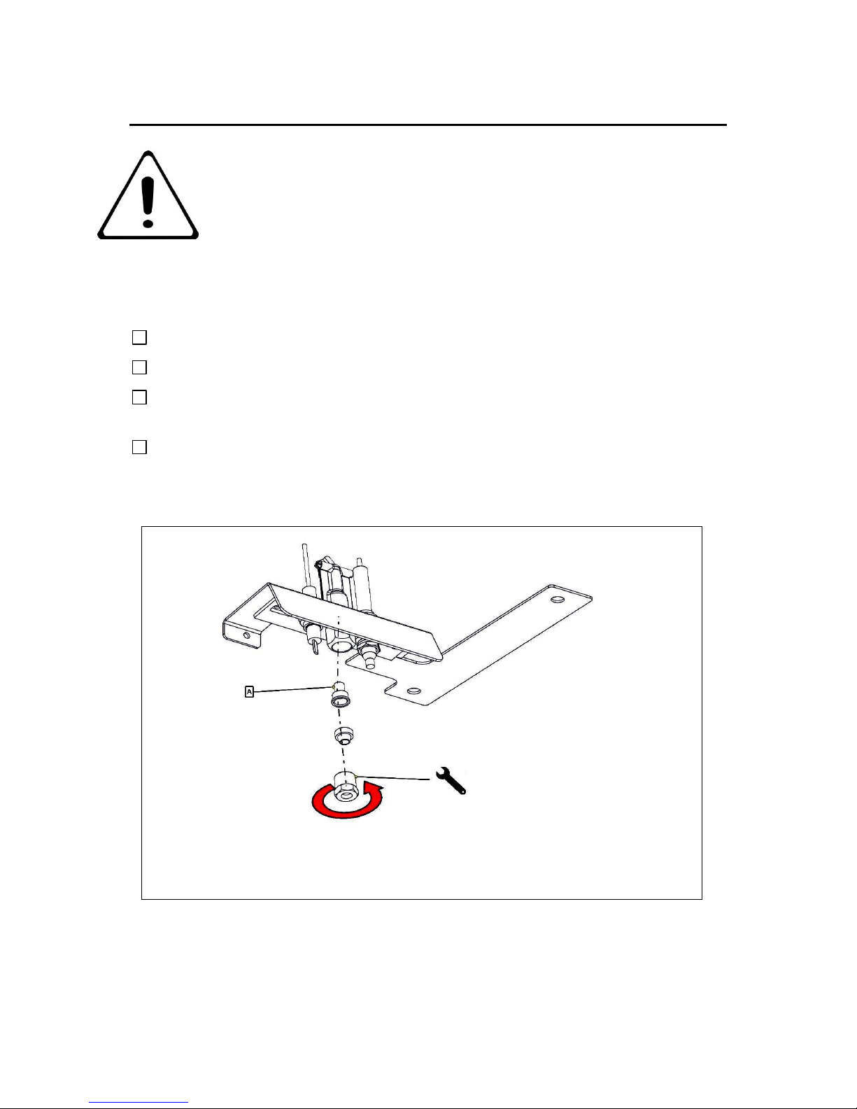
7.1 GAS CONVERSION CHECK LIST
Change injectors in burner(s) and pilots
Change gas type label.
G30, 29mb at the burner or adjust SIT onboard governor if supply pressure is higher
than 29mb.
.
G31 the pressure is 34.5mb at burner. (Adjust SIT onboard governor clockwise to
Maximum adjustment
A – PILOT INJECTOR
Page 23
23
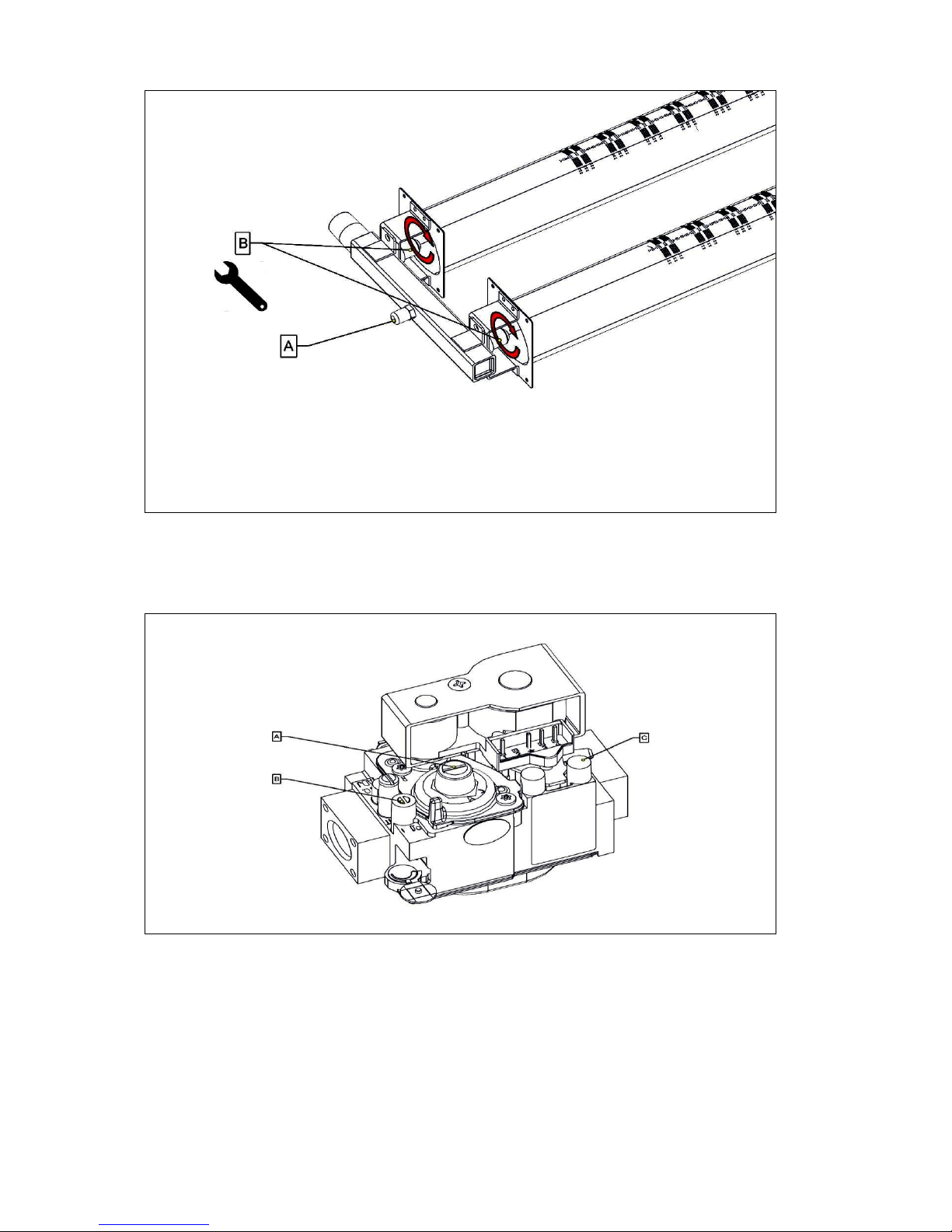
A - PRESSURE TEST NIBBLE
B- INJECTORS
A- PRESSURE ADJUSTMENT SCREW
B- OUTLET PRESSURE
C- INLET PRESSURE
Page 24
24
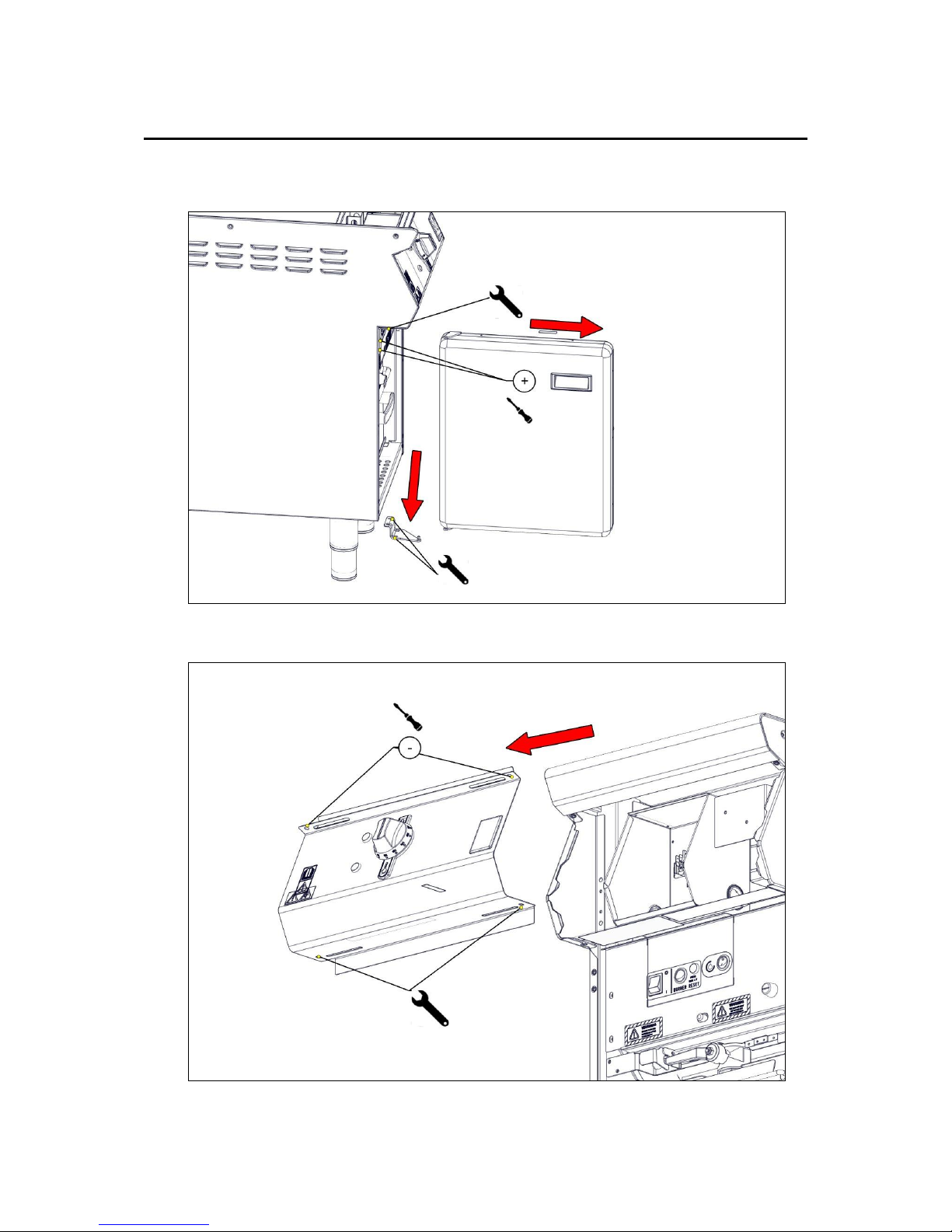
8 SERVICING
Turn off Electrical Power & Gas before Servicing
8.1 DOOR
8.2 CONTROL PANEL (REMOVE DOOR FIRST)
Page 25
25
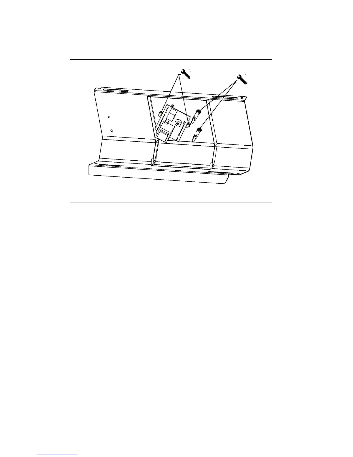
8.3 FASTRON CONTROLLER & NEONS
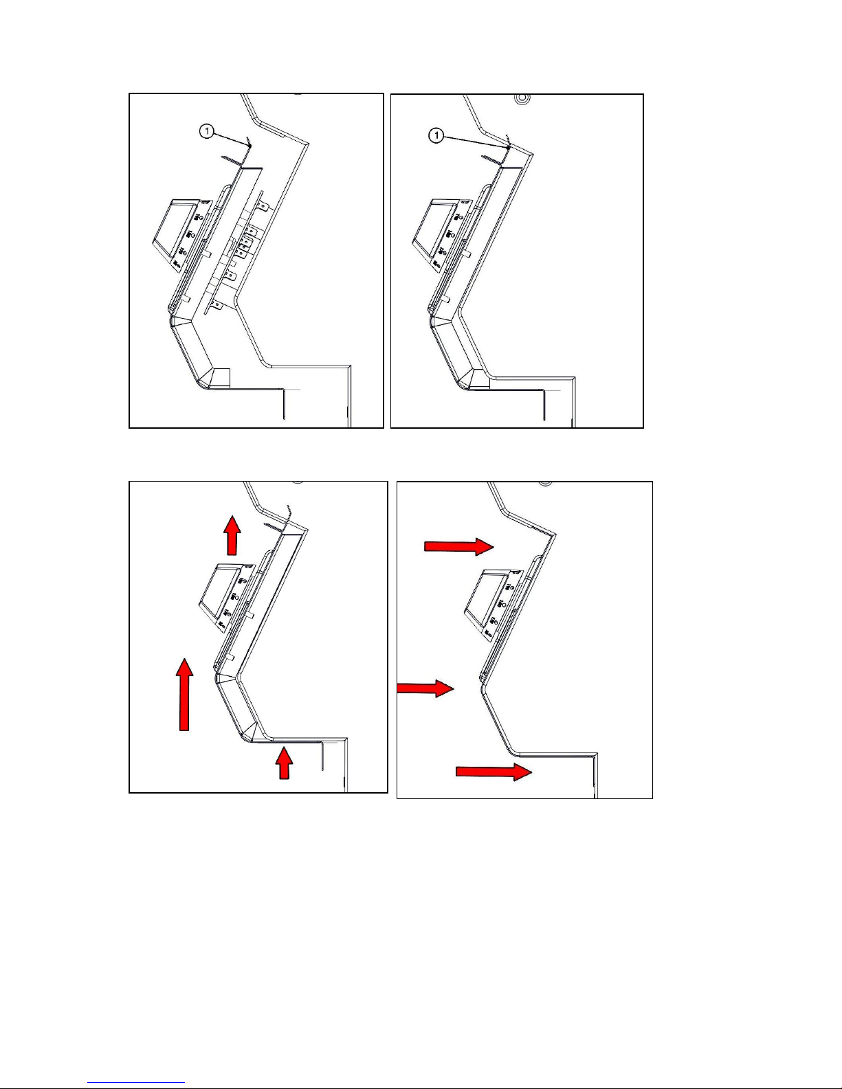
8.3.1 REFITTING CONTROL PANEL.
Align control panel with the front of unit.
Hook point 1 under hob as shown in diagram 2.
Slide panel up until base of panel hits side panels as shown in diagram 3.
Push panel in as shown in diagram 4 and fit screws.
Page 26
26
Diagram 1 Diagram 2
Diagram 3 Diagram 4
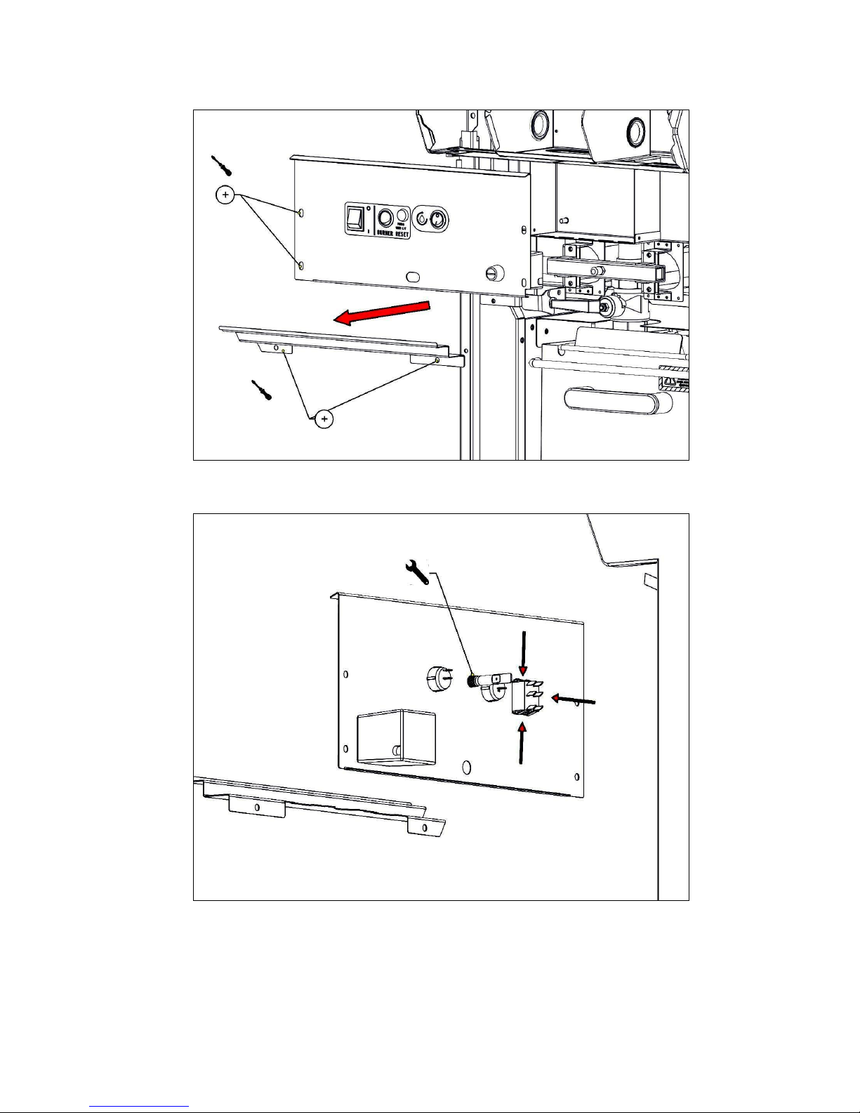
8.4 SWITCH PANEL
Page 27
27
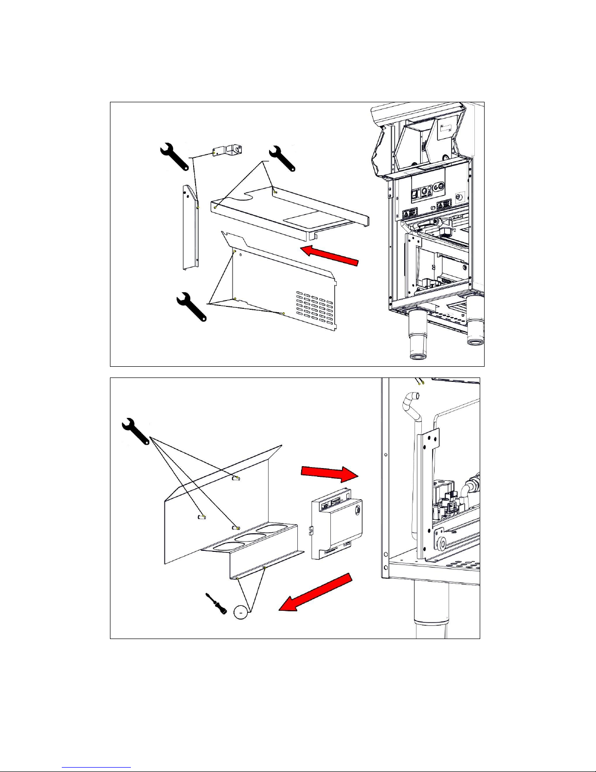
8.5 SWITCH & NEON REMOVAL
Page 28
28
8.6 ACCESS TO SPARK BOX
Page 29
29
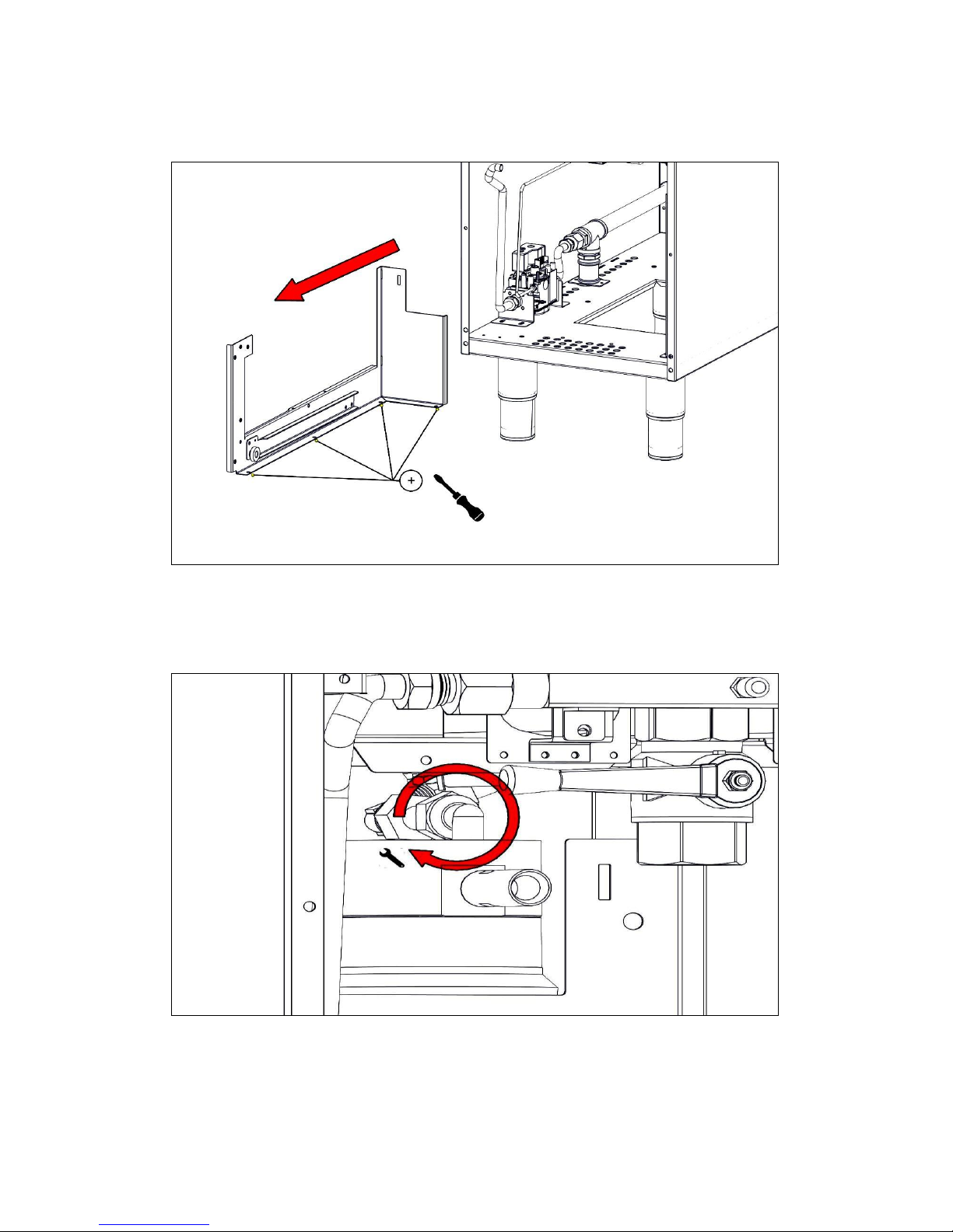
8.7 SIT GAS REGULATOR ACCESS
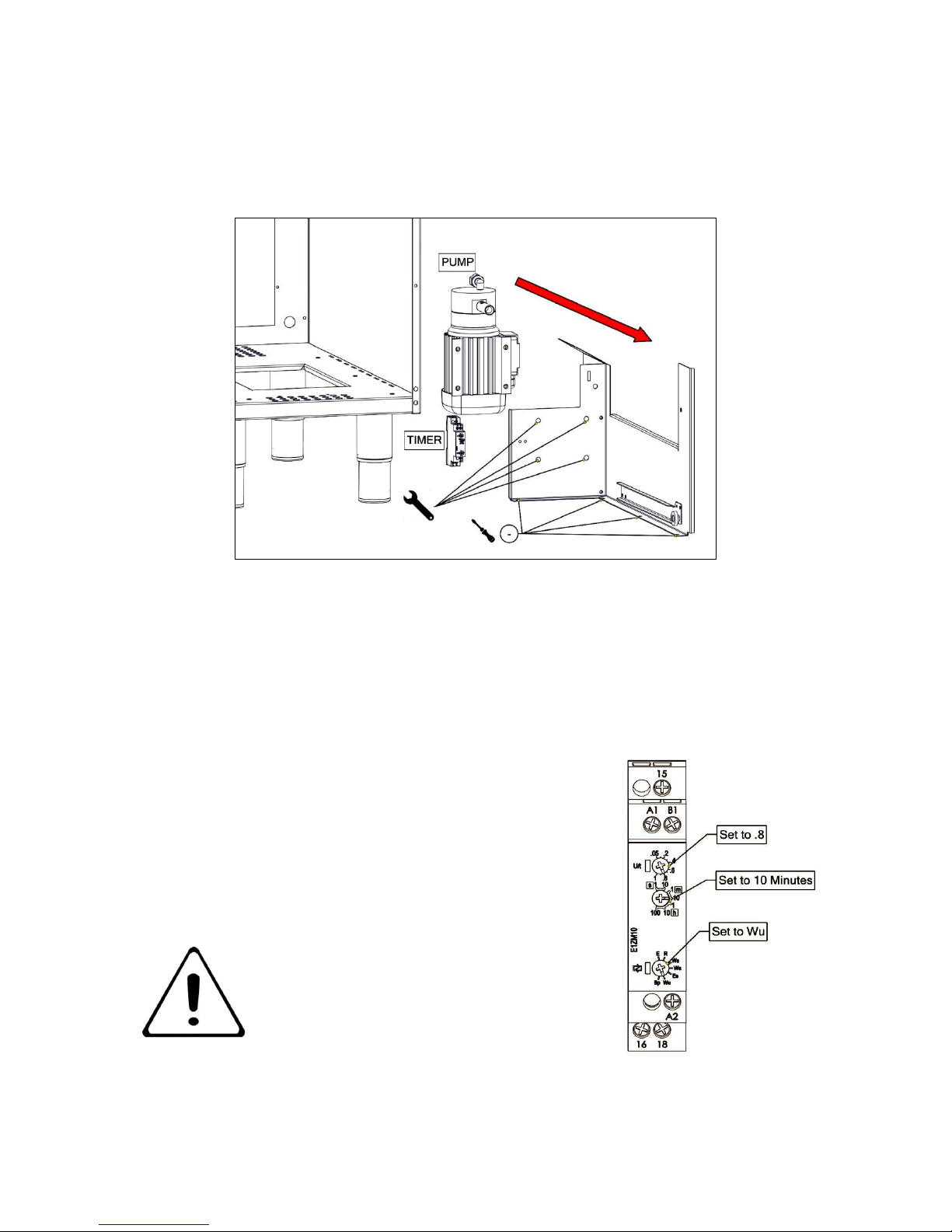
8.8 PUMP & TIMER REMOVAL
Page 30
30
8.9 PUMP & TIMER REMOVAL
8.10 Timer Pump Settings for 230 volts
The settings are top function set to 0.8
Middle function to 10 minutes
Base function set to Wu
GOVERNOR SUPPLIED IS PART OF THE
SIT GAS VALVE
Page 31
31
9 ACCESSORIES
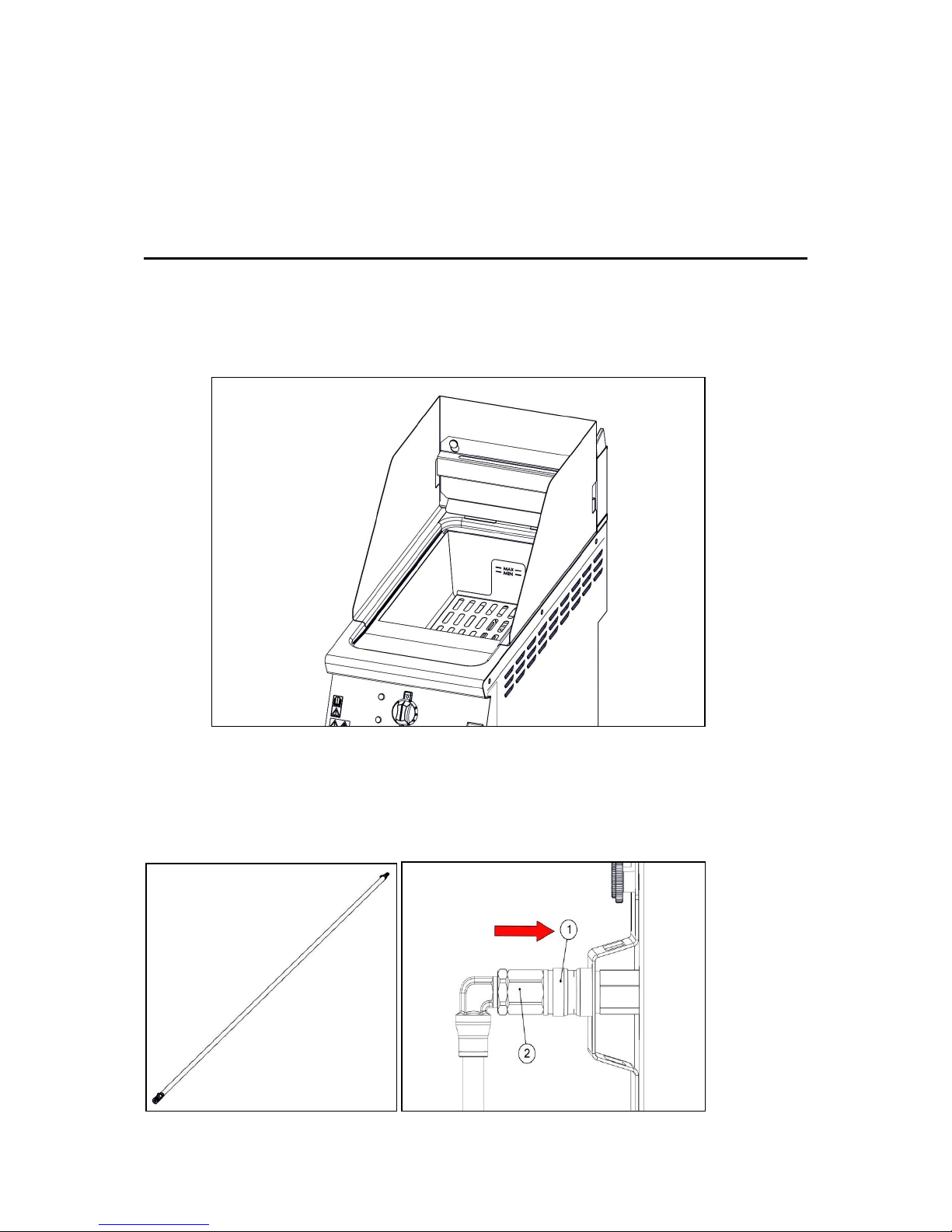
9.1 SPLASH GUARD. Remove basket hanging panel, position splash guard and refit
basket hanging panel.
9.2 DRAIN HOSE. Push quick release connection (1), remove part (2) and fit to hose then
fit hose to unit (1).
Page 32
32
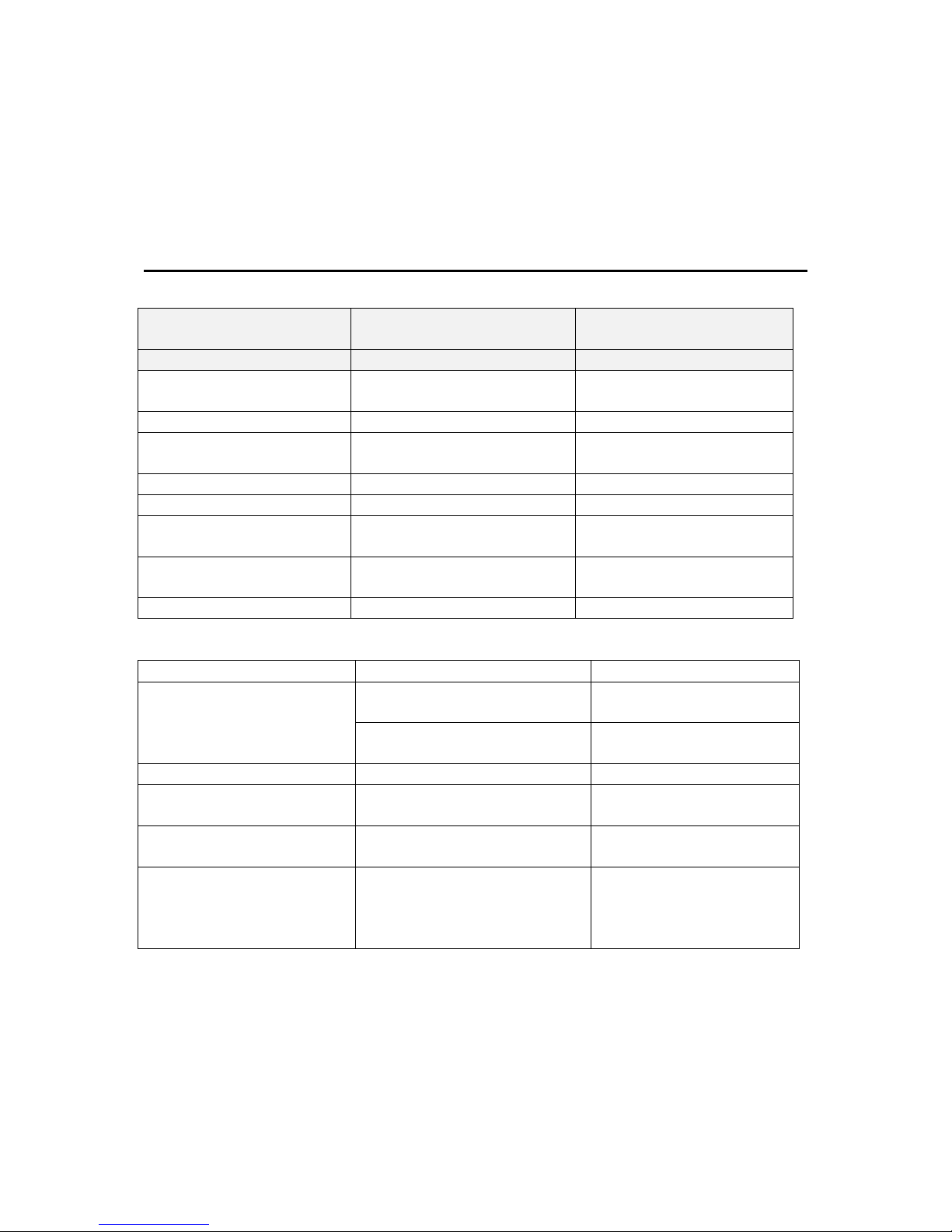
10 FAULT FINDING
FAULT
POSSIBLE CAUSES
REMEDY
Unit will not turn ON
No power to unit
Check mains power is
connected and turned on
Unit will not light
No gas to unit
Turn gas on
Safety cut out Neon is on
No gas has reached pilot
Press reset button for
further lighting attempts
Safety cut out activated
Overheating
Allow to cool below 180°c
Safety cut out activated
Low oil level
Add oil to min level mark
Pump will not run
Only runs when burner
switch is in off (0) position
Turn off (0) burner switch
Pump stops running
Pump has ran cycle
Allow the pump to cool
and then run once more
Pump stops running
Blocked pump
Clean Filters Regularly
Problem
Possible Cause
Possible Solution
Surge Boiling
Over loading with wet food
Reduce the amount of
wet food
Overloading with oil
Reduce the amount of
oil to the Min Level
Pan Not Draining
Blocked with debris
Clean drain hole
Oil not Filtering
Blocked filters with debris
Clean filters inside the
oil bucket
Debris in crumb tray in
fry pot
Fryer use
Clean crumb tray
Debris in being returned
to pan after filtering
Blocked filters in fryer
bucket and overflowing,
allowing unfiltered oil back
to pan
Ensure oil has time to
filter through strainer.
Heavily unfiltered oil can
block pump
Page 33

33
11 SPARE PARTS
PART NAME
FASTRON CONTROLER
NEON RED
NEON AMBER
PLIOT INJECTOR
BURNER INJECTOR
OPERATING THERMOCOUPLE
SAFETY THERMOCOUPLE
ON/OFF SWITCH
RESET SWITCH
PUMP SWITCH
PUMP
TIMER
PILOT ASSEMBLY
When ordering spare parts please quote the following;
Model Number
Serial number
Gas Type
This information will be found on data plate attached to the appliance
Visit our website for further spares information.
12 SERVICE INFORMATION
It is recommended to have a maintenance contract with a local service provider.
SERVICELINE CONTACT:
(UK only)
Phone: +441438 363 000
Warranty Policy Shortlist
For our warranty policy please go to www.falconfoodservice.com
Page 34
34
Page 35
35
Page 36
36
Page 37
37
Page 38

38
 Loading...