

Falcon G9081, F900 SERIES, G9181, G9042A, G9042 User, Installation And Servicing Instructions
...
1
F900 SERIES
User, installation and servicing instructions
SOLID TOP & RANGES
G9081/G9181
Read these instructions before use
T100892
Rev 9
Published: 08/09/2016
DATE PURCHASED:
MODEL NUMBER:
SERIAL NUMBER:
DEALER:
SERVICE PROVIDER:
2
Falcon Foodservice Equipment
HEAD OFFICE
Wallace View, Hillfoots Road, Stirling. FK9 5PY. Scotland.
WEEE Directive Registration No. WEEE/DC0059TT/PRO
At end of appliance life, dispose of appliance and any replacement parts in a safe
manner, via a licensed waste handler. Appliances are designed to be dismantled
easily and recycling of all material is encouraged whenever practicable.
Dear Customer,
Thank you for choosing Falcon Foodservice Equipment.
This manual can be downloaded from www.falconfoodservice.com Or scan
here
IMPORTANT: Please keep this manual for future reference.
3
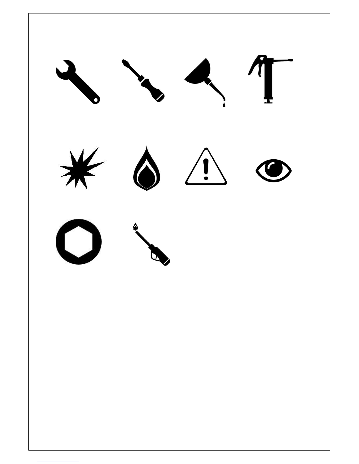
SYMBOLS
• SPANNER • SCREWDRIVER • COOKING OIL • GREASE
• SPARK IGNITION • FLAME • WARNING • VIEWPORT
• ALLEN KEY •IGNITER
4
These instructions are only valid if the country code appears on the appliance.
If the code does not appear on the appliance, refer to the technical instructions
for adapting the appliance to the conditions for use in that country.
Installation must meet national or local regulations. Attention must be paid to:
gas safety (installation & use) regulations, health and safety at work act, local
and national building regulations, fire precautions act.
To prevent shocks, all appliances must be earthed.
This equipment is for professional use only and must be used by qualified
persons.
The installer must instruct the responsible person(s) of the correct operation
and maintenance of the appliance.
Only competent persons are allowed to service or convert the appliance to
another gas type.
Gas appliances must have a stop cock fitted in the supply pipe work. The user
must be familiar with the location and operation of this device in order to turn
off the supply of gas in the event of an emergency.
Unless otherwise stated, parts which have been protected by the manufacturer
must not be adjusted by the installer.
Take care when moving an appliance fitted with castors.
The appliance must be serviced regularly by a qualified person.
Service intervals should be agreed with the service provider.
This appliance may be discolored due to testing.

5
Contents
1.0 APPLIANCE INFORMATION ......................................................................................................... 6
2.0 OPERATION ................................................................................................................................. 7
2.1 COMPONENT PARTS ............................................................................................................... 7
2.2 CONTROLS ............................................................................................................................... 8
2.3 USING THE APPLIANCE ............................................................................................................ 9
2.4 TURNING THE BURNERS OFF ................................................................................................ 11
3.0 CLEANING AND MAINTENANCE ................................................................................................ 11
3.1 HOB ....................................................................................................................................... 11
3.2 OVEN ..................................................................................................................................... 11
3.3 FLUE CAPPER ......................................................................................................................... 12
4.0 SPECIFICATION .......................................................................................................................... 13
4.1 TABLE A – Technical Data ...................................................................................................... 13
4.2 TABLE B – Heat Inputs ........................................................................................................... 14
5.0 DIMENSIONS / CONNECTION LOCATIONS ................................................................................ 15
6.0 INSTALLATION ........................................................................................................................... 16
6.1 SITING / CLEARANCES ........................................................................................................... 16
6.2 VENTILATION ......................................................................................................................... 16
6.3 GAS SUPPLY & CONNECTION ................................................................................................ 17
6.4 ASSEMBLY ............................................................................................................................. 17
6.5 COMMISSIONING - HOB ........................................................................................................ 18
6.6 COMMISSIONING – OVEN ..................................................................................................... 18
6.7 SUITING ................................................................................................................................. 19
7.0 CONVERSION ............................................................................................................................. 21
7.1 GAS CONVERSION CHECK LIST .............................................................................................. 21
8.0 SERVICING ................................................................................................................................. 22
8.1 CONTROL PANEL ................................................................................................................... 22
8.2 INJECTOR (HOB) .................................................................................................................... 23
8.3 PILOT (HOB) ........................................................................................................................... 23
8.4 REMOVAL OF DOOR .............................................................................................................. 24
8.5 INJECTOR (OVEN) .................................................................................................................. 25
8.6 PILOT (OVEN) ........................................................................................................................ 26
8.7 AERATION (HOB) ................................................................................................................... 26
8.8 GAS VALVE (HOB) .................................................................................................................. 27
8.9 GAS VALVE (OVEN) ................................................................................................................ 28
8.10 PRESSURE ADJUSTMENT ....................................................................................................... 29
8.11 GOVERNOR ............................................................................................................................ 29
9.0 FAULT FINDING ......................................................................................................................... 30
10.0 SPARE PARTS ............................................................................................................................. 31
11.0 SERVICING INFORMATION ........................................................................................................ 32
6
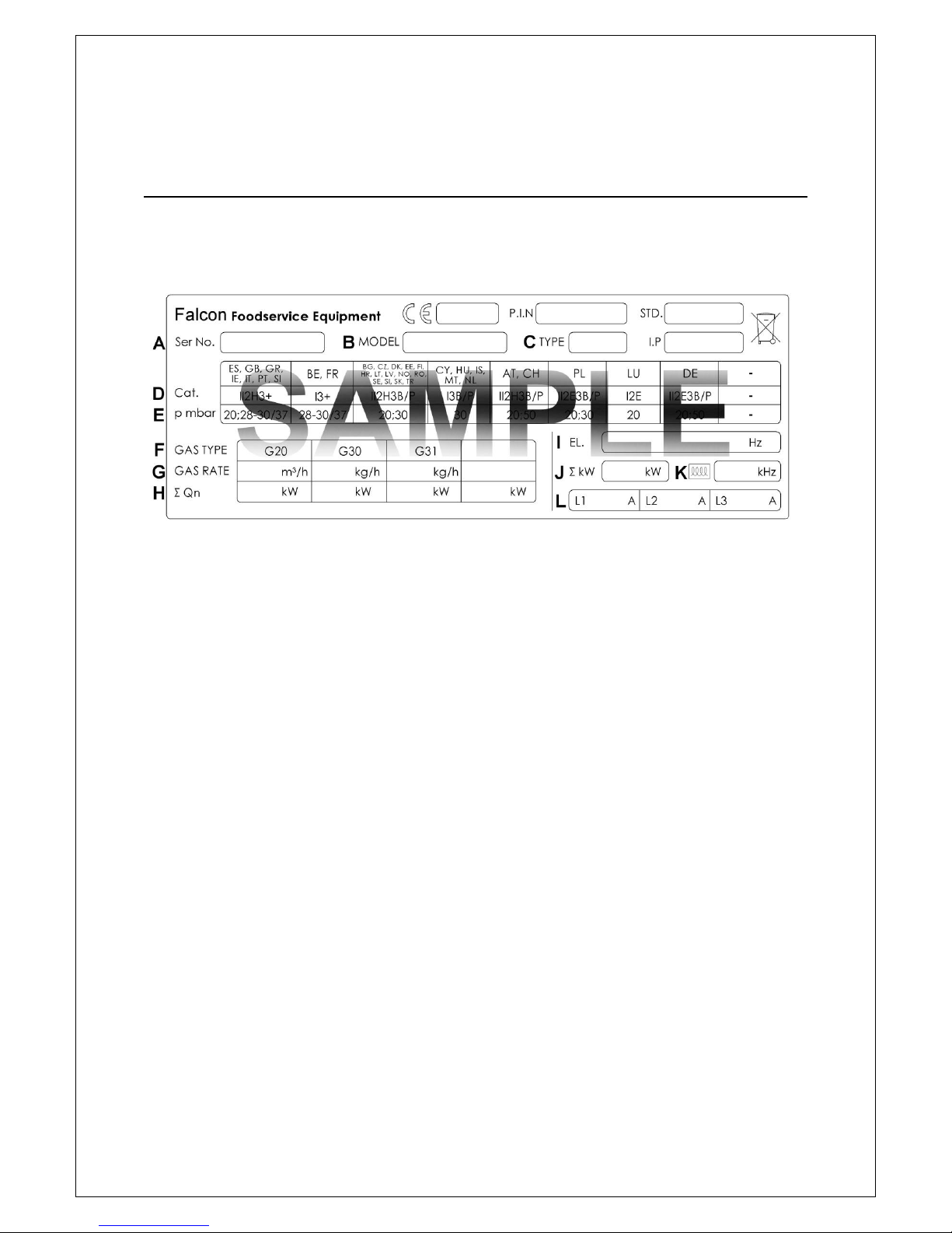
1.0 APPLIANCE INFORMATION
This appliance has been CE-marked on the basis of compliance with the relevant EU
directives for the heat inputs, gas pressures and voltages stated on the data plate.
A - Serial No
B - Model No
C - Flue Type
D - Gas Category
E - Gas Pressure
F - Gas Type
G - Gas Rate
H - Total Heat Input
I - Electrical Rating
J - Total Electrical Power
K - Magnetic Field Frequency
L - Electrical Phase Loading
7
2.0 OPERATION
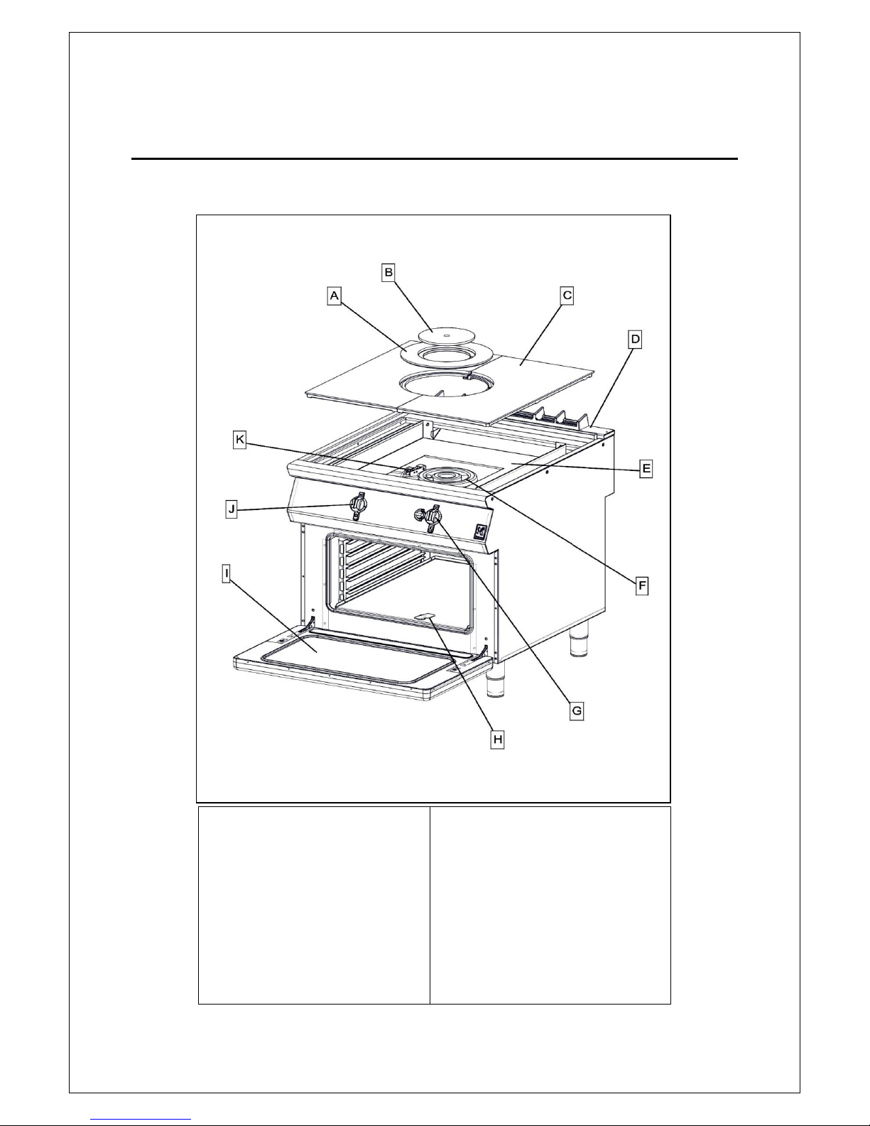
2.1 COMPONENT PARTS
A – Outer Ring
B – Inner Ring
C – Cast Plate
D – Flue Capper
E – Hob Tray
F – Hob Burner
G – Oven Control
H – Viewport
I – Door
J – Hob Control
K – Hob Pilot
8
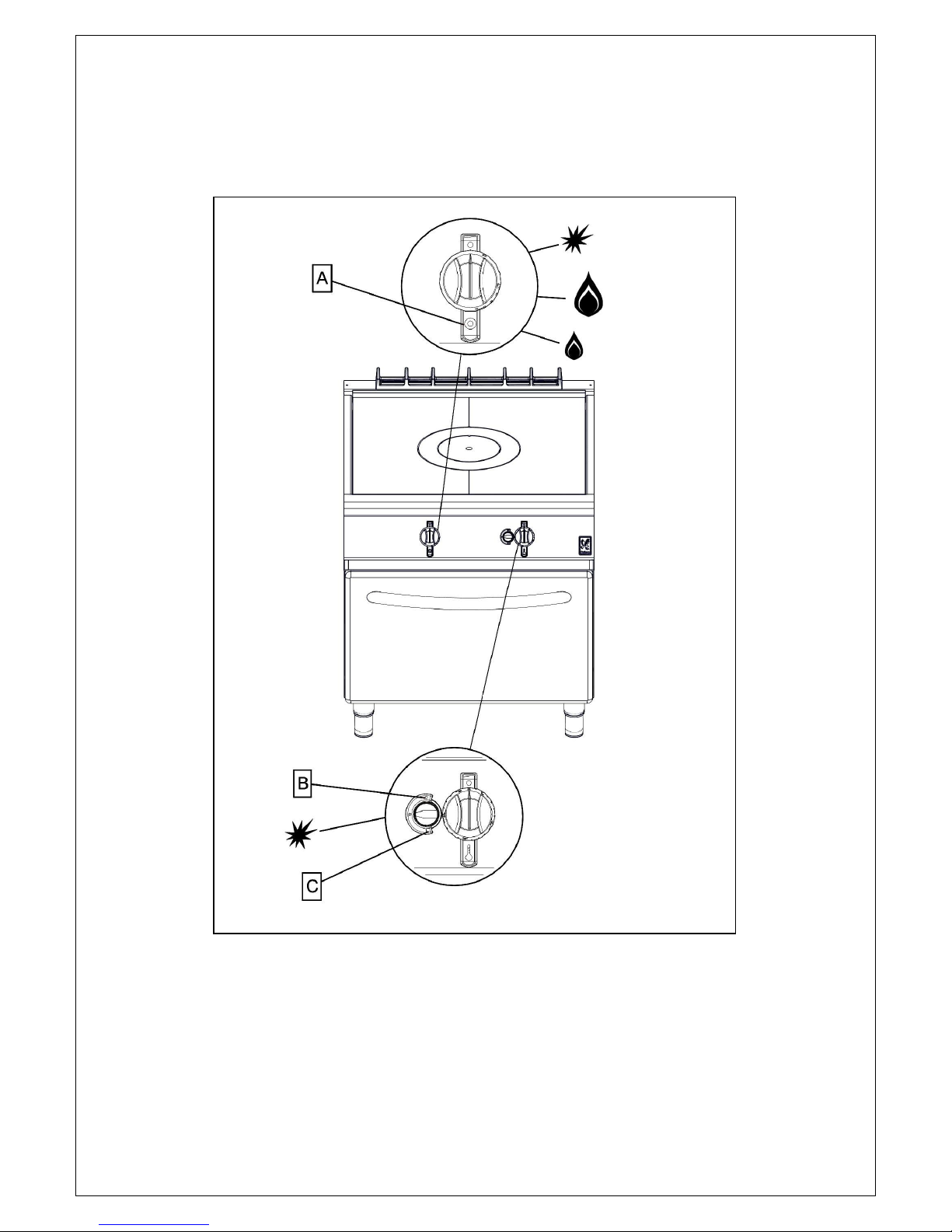
2.2 CONTROLS
A – Solid Top Burner
B – Oven Pilot OFF
C – Oven Pilot ON
9
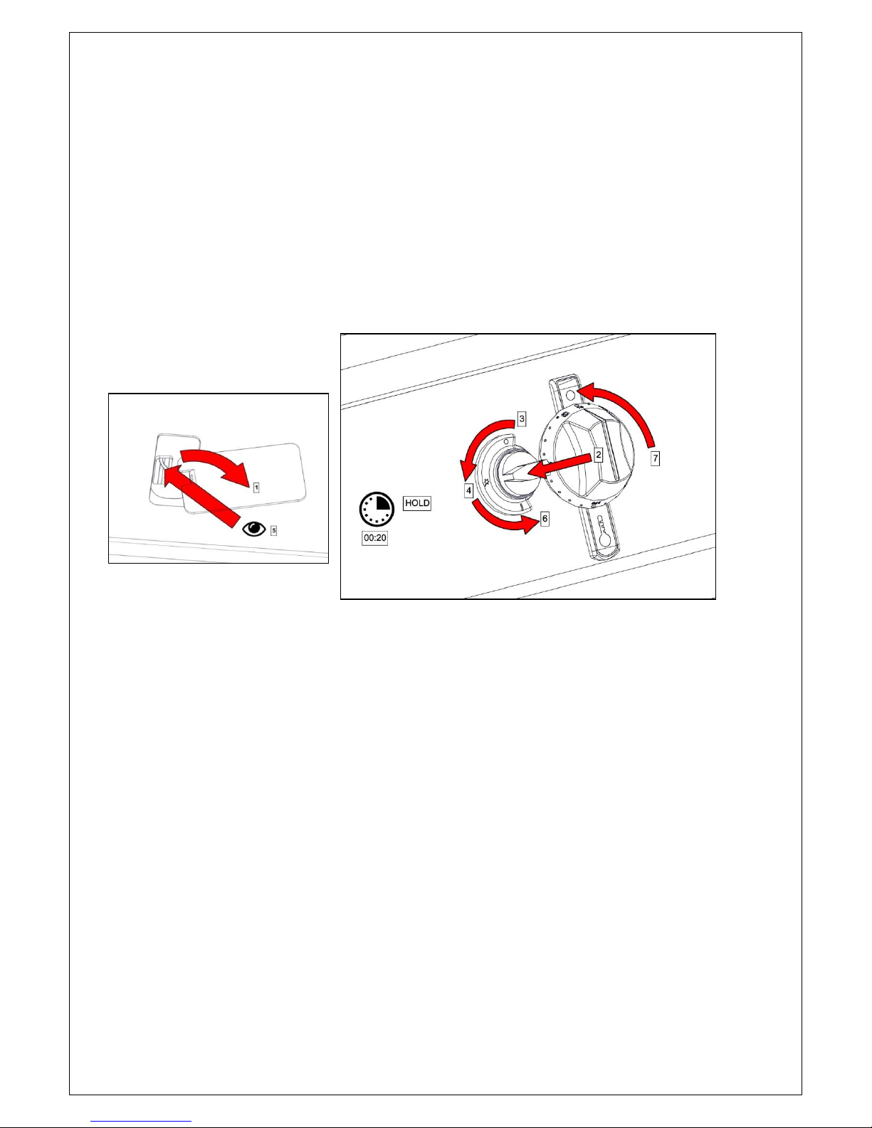
2.3 USING THE APPLIANCE
2.3.0 Before use, clean the appliance. See section 3.0.
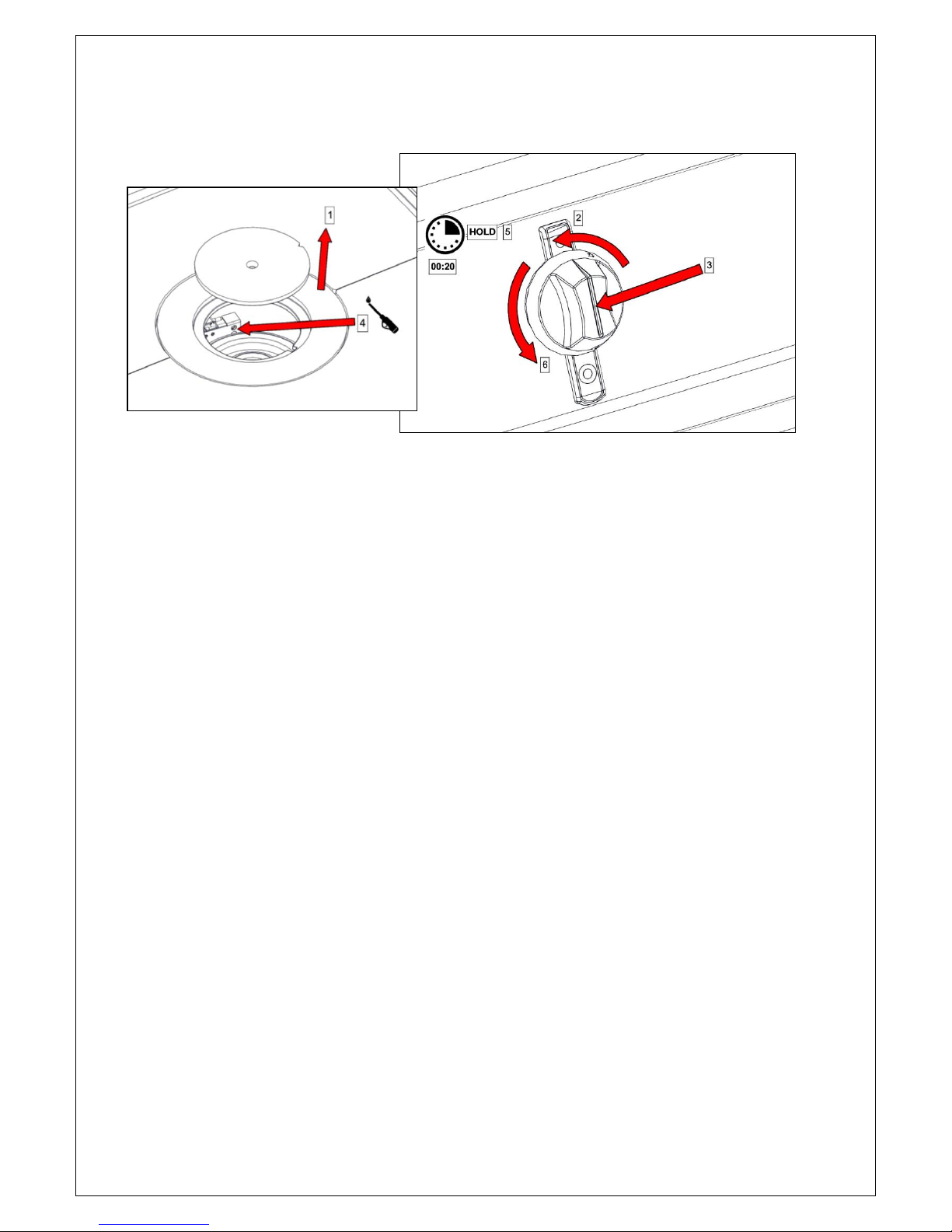
2.3.1 Oven - Ignite the Pilot burners as shown. Push the knob in to turn.
2.3.2 Use temperature control knob to adjust temperature. (Oven only)
Initial oven heat up time will be approximately 30 minutes from ambient.
Caution: Opening the oven door will result in the escape of hot air. Care should be taken to avoid
being burned by such action.
10
2.3.3 Hob – Ignite the Pilot burners as shown. Push the knob in to turn.
The minimum temperature of the hottest point of the solid top is 270˚C.
 Loading...