

Falcon G6478 Installation And Servicing Instructions
RZZ 349 Ref. 1
G6478 STEAMING OVEN
INSTALLATION and
SERVICING INSTRUCTIONS
The appliance must be installed and serviced by a competent person as stipulated by the Gas Safety
(Installation & Use) Regulations.
IMPORTANT
The installer must ensure that the installation of the appliance is in conformity with these instructions and
National Regulations in force at the time of installation. Particular att ention MUST be paid to -
Gas Safety (Installation & Use) Regulations
Health And Safety At Work etc. Act
Local and National Building Regulations
Fire Precautions Act
The appliance has been CE-marked on the basis of compliance with the Gas Appliance Directive for the
Countries, Gas Types and Pressures as stated on the Data Plate.
WARNING - TO PREVENT SHOCKS, ALL APPLIANCES WHETHER
GAS OR ELECTRIC, MUST BE EARTHED
On completion of the installation, these instructions should be left with the Engineer-in-Charge for reference
during servicing. Further to this, The Users Instructions should be handed over to the User, having had a
demonstration of the operation and cleaning of the appliance.
IT IS MOST IMPORTANT THAT THESE INSTRUCTIONS BE CONSULTED BEFORE INSTALLING AND
COMMISSIONING THIS APPLIANCE. FAILURE TO COMPLY WITH THE SPECIFIED PROCEDURES MAY
RESULT IN DAMAGE OR THE NEED FOR A SERVICE CALL.
PREVENTATIVE MAINTENANCE CONTRACT
In order to obtain maximum performance from this unit we would recommend that a Maintenance Contract be
arranged with AFE SERVICELINE. Visits may then be made at agreed intervals to carry out adjustments and
repairs. A quotation will be given upon request to the contact numbers below.
Falcon Foodservice Equipment
HEAD OFFICE AND WORKS
PO Box 37, Foundry Loan, Larbert.
Stirlingshire. Scotland. FK5 4PL
AFE SERVICE LINE CONTACT -
PHONE - 01438 363 000 FAX - 01438 369 900
Detailed recommendations are contained
in Institute of Gas Engineers
published documents :
IGE/ UP/ 1, IGE/ UP/ 2
BS6173 and BS5440
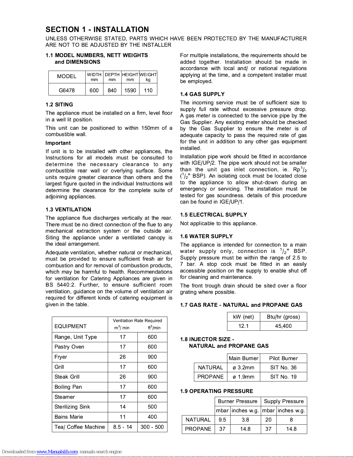
kW (net) Btu/hr (gross)
12.1 45,400
Main Burner Pilot Burner
SIT No. 36
SIT No. 19
ù 3.2mm
ù 1.9mm
NATURAL
PROPANE
mbar inches w.g.
3.8
14.8
9.5
37
NATURAL
PROPANE
mbar inches w.g.
20 8
37 14.8
Burner Pressure Supply Pressure
SECTION 1 - INSTALLATION
1.2 SITING
The appliance must be installed on a firm, level floor
in a well lit position.
This unit can be positioned to within 150mm of a
combustible wall.
Important
If unit is to be installed with other appliances, the
Instructions for all models must be consulted to
determine the necessary clearance to any
combustible rear wall or overlying surface. Some
units require greater clearance than others and the
largest figure quoted in the individual Instructions will
determine the clearance for the complete suite of
adjoining appliances.
1.3 VENTILATION
The appliance flue discharges vertically at the rear.
There must be no direct connection of the flue to any
mechanical extraction system or the outside air.
Siting the appliance under a ventilated canopy is
the ideal arrangement.
Adequate ventilation, whether natural or mechanical,
must be provided to ensure sufficient fresh air for
combustion and for removal of combustion products,
which may be harmful to health. Recommendations
for ventilation for Catering Appliances are given in
BS 5440:2. Further, to ensure sufficient room
ventilation, guidance on the volume of ventilation air
required for different kinds of catering equipment is
given in the table.
For multiple installations, the requirements should be
added together. Installation should be made in
accordance with local and/ or national regulations
applying at the time, and a competent installer must
be employed.
1.4 GAS SUPPLY
The incoming service must be of sufficient size to
supply full rate without excessive pressure drop.
A gas meter is connected to the service pipe by the
Gas Supplier. Any existing meter should be checked
by th e Gas Supplier to ensu re the meter is of
adequate capacity to pass the required rate of gas
for the unit in addition to any other gas equipment
installed.
Installation pipe work should be fitted in accordance
with IGE/UP/2. The pipe work should not be smaller
than the unit gas inlet connection, ie. Rp
1
/
2
(1/2" BSP). An isolating cock must be located close
to the appliance to allow shut-down during an
emergency or servicing. The installation must be
tested for gas soundness. details of this procedure
can be found in IGE/UP/1.
1.5 ELECTRICAL SUPPLY
Not applicable to this appliance.
1.6 WATER SUPPLY
The appliance is intended for connection to a main
water supply only, connection is
1
/2" BSP.
Supply pressure must be within the range of 2.5 to
7 bar. A stop cock must be fitted in an easily
accessible position on the supply to enable shut off
for cleaning and maintenance.
The front trough drain should be sited over a floor
grating where possible.
1.7 GAS RATE - NATURAL and PROPANE GAS
1.8 INJECTOR SIZE -
NATURAL and PROPANE GAS
1.9 OPERATING PRESSURE
EQUIPMENT
Ventilation Rate Required
m
3
/ min ft3/min
Range, Unit Type 17 600
Pastry Oven 17 600
Fryer 26 900
Grill 17 600
Steak Grill 26 900
Boiling Pan 17 600
Steamer 17 600
Sterilizing Sink 14 500
Bains Marie 11 400
Tea/ Coffee Machine 8.5 - 14 300 - 500
UNLESS OTHERWISE STATED, PARTS WHICH HAVE BEEN PROTECTED BY THE MANUFACTURER
ARE NOT TO BE ADJUSTED BY THE INSTALLER
MODEL
WIDTHmmDEPTHmmHEIGHTmmWEIGHT
kg
G6478 600 840 1590 110
1.1 MODEL NUMBERS, NETT WEIGHTS
and DIMENSIONS
A
B
C
3
1
2
A pressure test point is provided on burner inlet
supply, accessible when facia panel is removed.
1.10 BURNER ADJUSTMENT
The burner has a fixed air inlet and gas injector.
NO ADJUSTMENT IS REQUIRED.
The pressure must be checked as detailed in
Section 1.9.
SECTION 2 - ASSEMBLY and
COMMISSIONING
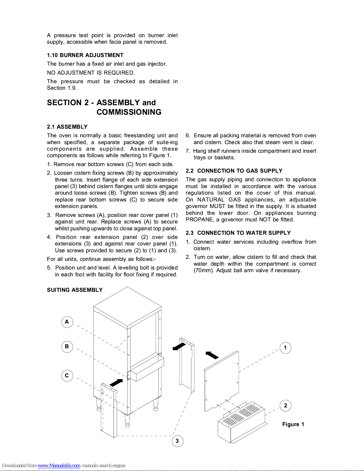
2.1 ASSEMBLY
The oven is normally a basic freestanding unit and
when specified, a separate package of suite-ing
components are supplied. Assemble these
components as follows while referring to Figure 1.
1. Remove rear bottom screws (C) from each side.
2. Loosen cistern fixing screws (B) by approximately
three turns. Insert flange of each side extension
panel (3) behind cistern flanges until slots engage
around loose screws (B). Tighten screws (B) and
replace rear bottom screws (C) to secure side
extension panels.
3. Remove screws (A), position rear cover panel (1)
against unit rear. Replace screws (A) to secure
whilst pushing upwards to close against top panel.
4. Position rear extension panel (2) over side
extensions (3) and against rear cover panel (1).
Use screws provided to secure (2) to (1) and (3).
For all units, continue assembly as follows:-
5. Position unit and level. A levelling bolt is provided
in each foot with facility for floor fixing if required.
SUITING ASSEMBLY
6. Ensure all packing material is removed from oven
and cistern. Check also that steam vent is clear.
7. Hang shelf runners inside compartment and insert
trays or baskets.
2.2 CONNECTION TO GAS SUPPLY
The gas supply piping and connection to appliance
must be installed in accordance with the various
regulations listed on the cover of this manual.
On NATURAL GAS appliances, an adjustable
governor MUST be fitted in the supply. It is situated
behind the lower door. On appliances burning
PROPANE, a governor must NOT be fitted.
2.3 CONNECTION TO WATER SUPPLY
1. Connect water services including overflow from
cistern.
2. Turn on water, allow cistern to fill and check that
water depth within the compartment is correct
(70mm). Adjust ball arm valve if necessary.
Figure 1
 Loading...