

Page 1

G3441/G3641/G3941
G3441R/G3641R/G3941R
G3641FR/G3941FR Griddles
USERS INSTRUCTIONS
SECTION 1 - GENERAL DESCRIPTION
SECTION 2 - LIGHTING and OPERATIONS
SECTION 3 - COOKING HINTS
SECTION 4 - CLEANING and MAINTENANCE
This appliance has been CE-marked on the basis of compliance with the Gas Appliance
Directive for the Countries, Gas Types and Pressures as stated on the data plate.
The appliance MUST BE installed by a competent person in compliance with the INSTALLATION AND
SERVICING INSTRUCTIONS and National Regulations in force at the time. Particular attention MUST
be paid to the following:
Gas Safety (Installation & Use) Regulations
Health and Safety at Work Act
Furthermore, if a need arises to convert the appliance for use with another gas, a competent person
must be consulted. Those parts which have been protected by the manufacturer MUST NOT be
adjusted by the User.
Users should be conversant with the appropriate provisions of the Fire Precautions Act and the
requirements of the Gas Safety Regulations. in particular the need for regular servicing by a
competent person to ensure the continued safe and efficient performance of the appliance.
WARNING - TO PREVENT SHOCKS, ALL APPLIANCES WHETHER GAS OR ELECTRIC,
MUST BE EARTHED.
Upon receipt of the User's Instruction manual, the installer must instruct the responsible person(s) of
the correct operation and maintenance of the Appliance. This equipment is ONLY FOR
PROFESSIONAL USE, and shall be operated by QUALIFIED persons. It is the responsibility of the
Supervisor or equivalent to ensure that users wear SUITABLE PROTECTIVE CLOTHING and to draw
attention to the fact that, some parts will, by necessity, become VERY HOT and will cause burns if
touched accidentally.
WEEE Directive Registration No. WEE/DC0059TT/PRO
At end of unit life, dispose of appliance and any replacement
parts in a safe manner, via a licenced waste handler.
Units are designed to be dismantled easily and recycling of all
material is encouraged whenever practicable.
Falcon Foodservice Equipment
HEAD OFFICE AND WORKS
Wallace View, Hillfoots Road, Stirling. FK9 5PY. Scotland.
SERVICELINE CONTACT
Phone: 01438 363 000 Fax: 01438 369 900
T100765 Ref. 2
Page 2
SECTION 1 GENERAL DESCRIPTION
DOMINATOR PLUS griddles are 400mm, 600mm and
900mm wide respectively. These appliances may be
installed on a counter, table or on the special purpose
floor stand supplied by Falcon. Units are of modular
dimensions which enable suites of appliances to be
installed in a matching line, either counter-mounted,
as these or floor mounted i.e. ranges and fryers.
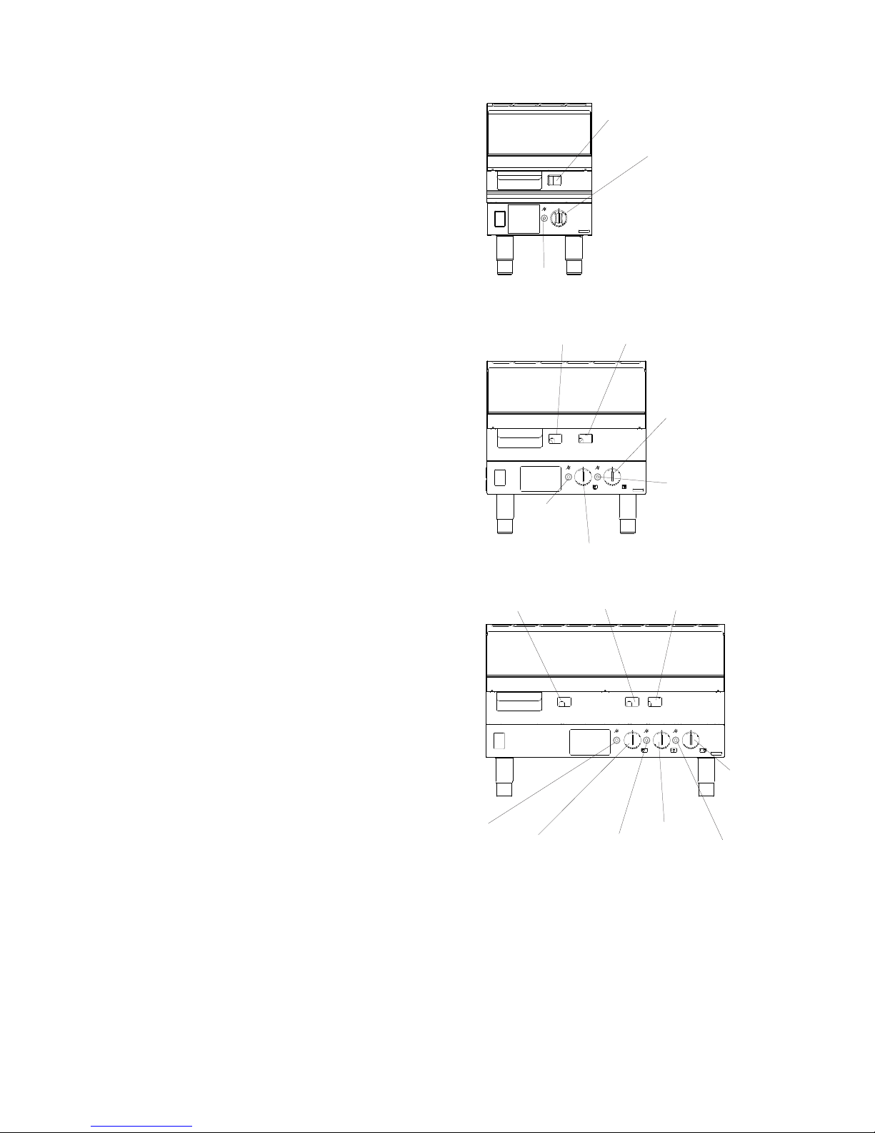
G3441 (400mm) has a rating of 5.3kW (nett) / 19,900
btu/hr (gross), controlled by combined thermostat and
flame failure device. Refer to Figure 1. Burner ignition is
by pilot, lit manually using the built-in piezo igniters.
Numbered gradients are identified on thermostat knob.
The fully ribbed G3441FR is identical in terms of rating.
G3641 (600mm) has a rating of 11kW (nett) / 41,800
btu/hr (gross). Controlled as detailed for G3441. Refer to
Figure 2. The half-ribbed G3641R and fully ribbed
G3641FR are identical in terms of rating.
The G3941 (900mm) griddle has three burners with a
rating of 16.5kW (nett) / 62,000 btu/hr (gross). Controlled
as detailed for G3441. Refer to Figure 3. The half-ribbed
G3941R and fully ribbed G3941FR are identical in terms
of rating.
Numbered gradients are identified on thermostat knobs.
Refer to Figure 4.
Thermostat control
Viewport
Figure 2
Figure 3
Centre viewportLH viewport
RH viewport
RH
thermostat
control
LH piezo
igniter
Centre
piezo igniter
RH piezo
igniter
Centre
thermostat
control
LH
thermostat
control
Piezo
igniter
Figure 1
LH viewport
RH viewport
LH piezo
igniter
LH
thermostat
control
RH
thermostat
control
RH piezo
igniter
G3441
G3641
G3941
Page 3

2.2 TURNING OFF THE BURNER
Refer to Figures 1, 2 & 3 and proceed as follows.
For Short Periods
To turn off burner leaving pilot lit, push knob in and turn
it clockwise to ignition symbol.
For Long Periods (e.g. overnight)
To turn off burner and pilot, push in knob and turn
it clockwise to OFF position.
Note - It can be seen from the above instructions that
every turn movement of the tap has to be preceded by
pushing it in.
SECTION 3 - COOKING HINTS
3.1 SEASONING THE GRIDDLE
Wash surface of griddle thoroughly to remove grease.
Rinse dry. Cover with a layer of salt to a depth of at least
one centimetre. Switch to LOW and heat for 1 hour and
allow to cool. Remove salt without scratching surface.
Wipe thoroughly with a dry cloth. Re-oil and heat gently
on low setting for 10 minutes.
3.2 HINTS ON USING THE GRIDDLE PLATE
Getting the best use out of this type of appliance is largely
a matter experience coupled with the particular task in
hand. It is impractical to provide detailed instructions for
cooking every type of food but obviously the plate surface
temperature must be regulated for different needs.
For example, some food products need a low
temperature whereas meat, i.e. steaks, chops,
beefburgers etc. require a considerably higher
temperature to achieve successful results.
It must also be borne in mind that food will absorb heat
from plate therefore when griddle is cooking large
quantities, it may be found necessary to have a higher
gas setting than may be required for small batches.
DO NOT leave griddle with the gas at HIGH setting when
not actually cooking. If it is desired to maintain plate heat
under these conditions it is important to turn down to the
LOW setting. This will effect economy of gas and prevent
the plate from overheating.
From cold, allow approximately 22 minutes pre-heat to
enable griddle to be ready for high temperature cooking.
The plate temperature will be approximately 320°C after
this duration.
When using intermediate tap settings, endeavour to
adjust all taps similarly to achieve even heating over the
entire plate. When turned to LOW position, this condition
will be achieved automatically and provides a
maximum temperature of 160°C.
Off
Pilot Ignition
Maximum Position
Minimum Position
SECTION 2 LIGHTING and OPERATIONS
The minimum temperature at the hottest point of the
griddle plate is 273°C
Safety Precautions
A stopcock must be fitted in gas pipe supplying the unit.
The User must be familiar with the location and operation
of this to enable it to turned off in an emergency.
2.1 Lighting The Burner
Refer to Figure 4 for control positions.
a) Push tap in and turn it anti-clockwise to ignition
position (stylised star symbol)
b) While holding tap in fully at ignition position, press
igniter button; repeat as necessary until pilot lights
(visible through window in control panel)
c) Once pilot is lit, hold tap in fully for a further
20 seconds then release it. If pilot goes out,
wait 3 minutes, and then repeat from (b).
d) When pilot is established, push tap in and turn
anti-clockwise to first gradient (next to Position 4)
to light burner.
e) Plate temperature can then be set by pushing tap in
and turning it anti-clockwise to desired location.
Repeat steps (a) through (e) for all burners.
If a wax taper is used, ensure taper is inserted in hole for
a maximum of 3 seconds at a time. This will prevent
dripping wax from blocking pilot hole. Repeat procedure
until pilot flame becomes lit.
If the burner is extinguished either intentionally or
otherwise, NO ATTEMPT to re-light the gas should be
made until at least 3 minutes have elapsed.
Figure 4 - Control Knob Details
Page 4

SECTION 4 CLEANING and MAINTENANCE
1. Turn unit off and allow to cool down.
2. Use a scraper to remove food debris.
3. Drain any liquid fat present into the drain jug.
4. Allow plate to cool until it is "just warm".
5. Use warm water and detergent on a non-abrasive
scourer to wash down the plate surface.
6. Drain excess soiled water into drain jug.
7. Rinse and dry plate surface thoroughly.
8. Lubricate plate surface by applying some cooking oil.
9. Drain, wash, rinse and dry jug before replacing it.
SECTION 5 - SPARE PARTS
The following parts may require replacing during the life
of this appliance.
Thermocouple
Gas ignition electrode
Piezo igniter
Thermostat
Note: Thermostat is supplied as standard with a natural
gas bypass screw. When replacing this component on
propane models, the bypass screw needs to be removed
from faulty control to be replaced.
 Loading...