

Page 1
DOMINATOR
PLUS
GAS RANGE APPLIANCES
(Refer to Section 1.1 for models covered by this document)
INSTALLATION and SERVICING
INSTRUCTIONS
This appliance must be installed and serviced by a competent person as stipulated by the Gas
Safety (Installation & Use) Regulations.
IMPORTANT
The installer must ensure that the installation of the appliance is in conformity with these instructions and
National Regulations in force at the time of installation. Particular attention MUST be paid to:
Gas Safety (Installation & Use) Regulations
Detailed recommendations are contained in
Institute of Gas Engineers published documents:
IGE/UP1, IGE/UP/2
BS6173 and BS5440
Health And Safety At Work etc. Act
Local and National Building Regulations
Fire Precautions Act
These appliances have been UKCA/CE-marked based on compliance with the Gas Appliance Regulations/
Product Safety and Metrology Regulations for the Countries, Gas Types and Pressures as stated on the data
plate.
WARNING: - TO PREVENT SHOCKS, ALL APPLIANCES WHETHER GAS OR ELECTRIC, MUST BE
EARTHED.
On completion of the installation, these instructions should be left with the Engineer-in-Charge for
reference during servicing. Further to this, The Users Instructions should be handed over to the User,
having had a demonstration of the operation and cleaning of the appliance.
IT IS MOST IMPORTANT THAT THESE INSTRUCTIONS BE CONSULTED BEFORE INSTALLING
AND COMMISSIONING THIS APPLIANCE. FAILURE TO COMPLY WITH THE SPECIFIED
PROCEDURES MAY RESULT IN DAMAGE OR THE NEED FOR A SERVICE CALL.
PREVENTATIVE MAINTENANCE CONTRACT
To obtain maximum performance from this unit regular servicing of the appliance should be undertaken to
ensure correct operation, it is functioning as intended, and safe to use. We recommend servicing in
accordance with SFG20 Maintenance Schedules and as a minimum, after 2,500 hours of use, or annually,
whichever comes first and that a maintenance contract be arranged with an appointed service contact. Visits
may then be made at agreed intervals to carry out adjustments and repairs.
WEEE Directive Registration No.
WEE/DC0059TT/PRO At end of unit life, dispose of
appliance and any replacement parts in a safe
manner, via a licensed waste handler.
Units are designed to be dismantled easily and recycling
of all material is encouraged whenever practicable.
Falcon Foodservice Equipment
HEAD OFFICE AND WORKS
Wallace View, Hillfoots Road, Stirling. FK9 5PY. Scotland.
Phone: 01786 455200
T100753 Ref. 12
Page 2
2
SECTION 1 - INSTALLATION
UNLESS OTHERWISE STATED, PARTS WHICH HAVE BEEN PROTECTED BY THE MANUFACTURER ARE
NOT TO BE ADJUSTED BY THE INSTALLER.
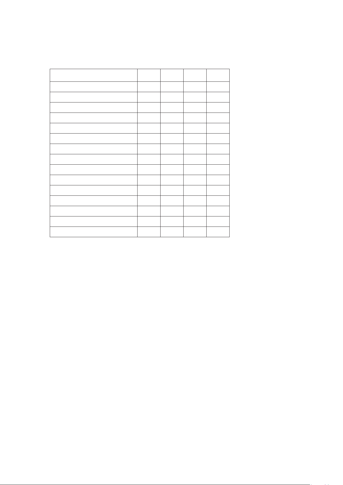
1.1 MODEL NUMBERS, NETT WEIGHTS and DIMENSIONS
Model
Width
(mm)
Depth
(mm)
Height
(mm)
Weight
(kg)
G3101 Six Burner Range
900
770
890
114
G3101D Six Burner Range
900
770
890
114
G3107 Solid Top Range
900
770
890
137
G3107D Solid Top Range
900
770
890
114
G3117 General Purpose Oven
900
770
890
120
G3117 GP Oven on Stand
900
770
1310
129
G3117/2 Two Tier GP Oven
900
770
1715
158
G3117D General Purpose Oven
900
770
890
120
G3117D GP Oven on Stand
900
770
1310
129
G3121 Six Burner Boiling Top
900
770
890
75
G3122 Two Burner Boiling Top
400
770
890
28.5
G3124 Four Burner Boiling Top
600
770
890
54
G3127 Solid Top Boiling Table
900
770
890
103
G3161 Four Burner Range
600
770
890
88
G3161D Four Burner Range
600
770
890
88
1.2 SITING
The appliance should be installed on a level, fireproof surface, in a well lit and draught free position.
If the floor is constructed of combustible material, then local fire requirements should be checked
to ensure compliance. A clear space of 150mm should be left between rear and side of unit and
any combustible wall.
Important
If a unit is to be installed in suite formation with other matching appliances, the instructions for all
models must be consulted to determine the necessary clearances to any combustible rear wall or
overlying surface. Some models require greater clearances than others and the largest figure quoted
in individual instructions will therefore determine the clearance for the complete suite of adjoining
appliances.
The oven flue discharges vertically through hob rear. There must be no direct connection of flue to
any mechanical extraction system or to the outside air. Open top burners discharge combustion
products directly into the room.
Care should be taken not to disturb the air combustion admission nor the combustion products
evacuation of appliances fitted with open burners .
1.3 VENTILATION
Adequate ventilation must be provided to supply sufficient fresh air for combustion and allow easy
removal of combustion products which may be harmful to health. Recommendations for Ventilation
of Catering Appliances are given in BS5440:2.
For multiple installations the requirements for individual appliances should be added together.
Installation should be made in accordance with local and/or national regulations applying at the
time. A competent installer MUST be employed.
Page 3

3
1.4 GAS SUPPLY
The incoming service must be of sufficient size to supply full rate without excessive pressure drop.
A gas meter is connected to the service pipe by gas supplier. Any existing meter should be
checked by supplier to ensure it is of adequate capacity to pass required rate for appliance in
addition to any other gas equipment installed.
Installation pipe work should be fitted in accordance with IGE/UP/2. The pipe work should be of
adequate size but not smaller than unit gas inlet connection, ie. Rp¾ (¾” B.S.P.). An isolating cock
must be located close by to allow shut-down during an emergency or servicing.
If flexible tube is used, the gas supply tubing or hose shall comply with national requirements in force.
These will be periodically examined and replaced as necessary.
The installation must be tested for gas tightness. Procedure details can be found in IGE/UP/1.
The adjustable governor supplied must be fitted to natural gas appliances.
1.5 ELECTRICAL SUPPLY
Not applicable to this appliance.
1.6 WATER SUPPLY
Not applicable to this appliance.
1.7 HEAT INPUTS - NATURAL and PROPANE GAS (kW net & Btu/hr gross)
1.7.1 Total Inputs
Model
kW
Btu/hr
I3B/P
I3+
G3101/3101D Six Burner
38.9
146,000
30.8
G3161 Four Burner
26
97,600
21.8
G3107/3107D Solid Top
17.4
65,400
15.6
G3121 Six Burner BT
31.8
120,000
25.5
G3122 Two Burner BT
10.6
40,000
8.5
G3124 Four Burner BT
21.2
79,600
17
G3127 Solid Top
10.3
38,700
10.3
G3117/3117D Oven
7.1
26,700
5.3
G3117/3117D On Stand
7.1
26,700
5.3
G3117/2 Two Tier
14.2
53,400
10.6
1.7.2 Individual Inputs (kW nett & Btu/hr gross)
Model
Natural
I2H
Propane
I3P
Butane
I3+ and I3B/P
Open Top
5.3
5.3
4.25
900mm
7.1
7.1
5.3
600mm
4.8
4.8
4.8
Solid Top
10.3
10.3
10.3
1.7.3 Individual Low Inputs (kW nett & Btu/hr gross)
Model
kW
Btu/hr
Open Top
1.1
4,100
Solid Top
4.8
18,000
Page 4
4
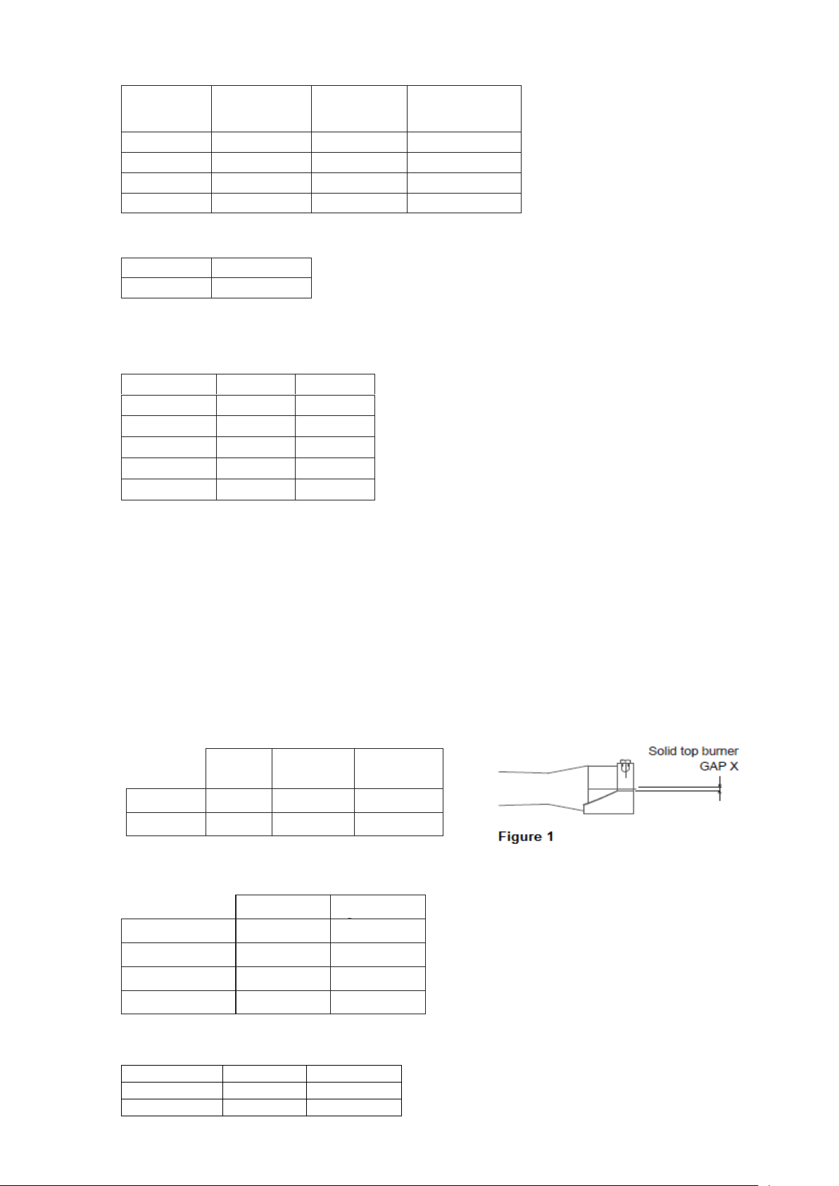
1.8 INJECTOR DIAMETERS
Model
Natural
I2H
Propane
I3P
Butane
I3+ and I3B/P
Open Top
Ø1.93mm
Ø1.2mm
Ø1.05mm
900mm
Ø2.2 mm
Ø 1.35mm
Ø1.15mm
600mm
Ø1.8mm
Ø 1.09mm
Ø1.0mm
Solid Top
Ø2.65mm
Amal 360
Amal 360
1.8.1 Solid Top Pilot Injectors
Natural Gas
Propane Gas
SIT No. 36
SIT No. 19
1.9 GAS PRESSURE ADJUSTMENT NATURAL and PROPANE GAS
The following supply pressures apply to all units :-
Gas type
mbar
Inches w.g.
Natural Gas
20
8
Propane Gas
37
14.8
I3+ Propane
37
14.8
I3+ Butane
29
11.6
I3B/P
29
11.6
Pressure test point is located on RH side of gas manifold situated behind front control facia.
An adjustable governor (¾" BSP) is provided on Natural Gas units. This should be adjusted to
achieve an operating pressure at control manifold of 15mbar (6 inches w.g.).
For multi-burner systems, approximately half of the burners should be on when setting governor
pressure.
1.10 BURNER ADJUSTMENT NATURAL and PROPANE GAS
1.10.1 Burner Aeration
Open top and oven burners are fitted with fixed injectors and set aeration apertures. NO
ADJUSTMENT is possible.
Solid top burners have fixed injectors and aeration shroud. Shroud adjustment required
(see Fig 1).
1.10.2 Bypass Screw Diameters
Minimum gas flow to burner is governed by size of fixed by-pass screw hole as follows:-
Natural Gas
Propane
Model
Marked
Marked
Open Top
76
51
900mm Oven
93
55
600mm Oven
76
51
Minimum gas flow for solid top is set by adjustment. Connect a manometer to burner pressure
test point on injector block and test adjustment.
Natural
Gas
Propane
Gas
I3B/P
I3+
Model
Gap X
Gap X
Gap X
Solid Top
4mm
4mm
10mm
Gas type
mbar
Inches w.g
Natural Gas
2
0.8
LP Gases
6
2.4
Page 5
5
SECTION 2 - ASSEMBLY and COMMISSIONING
Note - Take care when removing cast iron components as they are heavy items.
Pan Support – 5kg
2.1 ASSEMBLY Note
The following paragraphs should be read as applicable to the unit being assembled.
a) Unpack appliance and place it in position using feet adjusters to level appliance.
b) Units with castors should be fitted with accessories supplied according to separate
instructions provided.
c) Open oven door, pull out shelves and base panel. Check burner spark igniter arrangements
are correctly located and secured. Ensure ALL packing, etc. is removed from oven.
Replace all parts in reverse sequence.
d) Check open top and remove tape, packing, etc. from hob area and ensure that all burners and
pan supports are secured in position. The open top burner heads fit loosely upon aluminium
bases of lift-off construction.
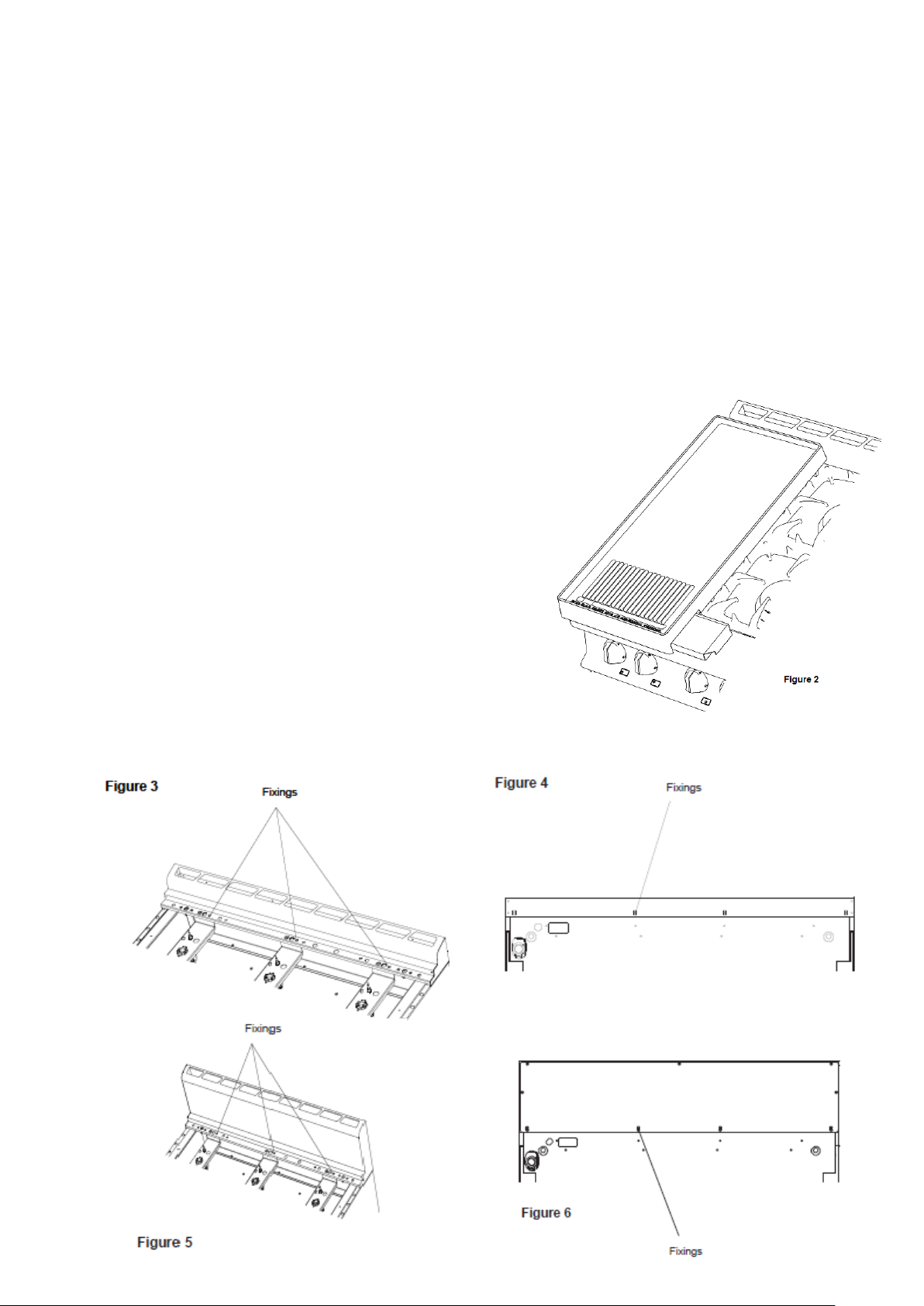
2.1.1 Fryplate Accessory
If fryplate (Figure 2) is supplied, refer to user instructions for
details. Important note: this should be operated on a low
flame setting only.
2.1.2 Flue Accessory
A tall flue is available as an accessory that may be
substituted for standard type supplied with unit.
Details of the alteration process are indicated in Figures 3
through 6.
Remove hob as detailed in Sections 3.2.2 and 3.2.3. Undo
and remove fixings at locations shown in Figure 3.
Remove fixings at rear detailed in Figure 4.
Install replacement flue as detailed in Figure 5 and
secure using existing fixings at hob and rear at positions indicated in Figures 5 and 6.
Important Note: It is not possible to fit a splashplate / plateshelf to a unit fitted with a tall flue.
Page 6

6
2.2 CONNECTION TO GAS SUPPLY
Connect appliance to gas supply and ensure that the governor supplied is fitted on NATURAL gas
installations. Test for gas tightness.
The integral gas supply downstream of gas valve may be checked by applying leak detection spray with
burner lit. Appliance inlet connection terminates at upper rear RH side in Rp¾ (¾" BSP female).
2.3 CONNECTION TO ELECTRICAL SUPPLY
Not applicable to these appliances.
2.4 CONNECTION TO WATER SUPPLY
Not applicable to these appliances.
2.5 COMMISSIONING THE APPLIANCE
Important - Prior to operation, ensure that ALL packing material has been removed.
2.5.1 Setting the Gas Pressure
a) It is necessary to check gas pressure during commissioning and a suitable gauge must
be connected to test point on RH side of supply manifold (situated behind front control facia).
b) Turn on main gas valve at supply to unit.
c) Light three open top burners as detailed in Section 2.5.3. Gas supply pipes may contain air
so repeat procedure until burner lights.
d) Adjust governor (Natural gas installations only) at unit rear to relevant pressure setting found in
Section 1.9. To increase pressure - turn screw clockwise (or anti-clockwise to decrease).
Check again after 15 minutes of operation.
e) Disconnect gauge. Replace test point sealing screw and test for gas tightness.
2.5.2 Checking Performance of the Controls
a) Light open top or oven as detailed in Section 2.5.3. Check ignition is smooth and without
delay. Repeat operation several times.
b) Place a thermocouple at oven centre and select 210°C setting. Allow oven to heat up and check
temperature is 210°C (+/-10°C). If reading is outwith specified range, the thermostat may
be faulty. In this case, unit should be serviced (see thermostat replacement and calibration
procedure). Turn gas supply to oven OFF and allow a sufficient cool-down period before
removing thermostat.
2.5.3 Lighting Sequence Important
Prior to operation, ensure ALL packing material has been removed from appliance.
Open Top
1.
Ensure mains gas is turned on.
2.
To light hob burners, press knob and turn to full flame position. Ignite burners using taper or
match. Hold in knob for 20 seconds and then release. Burner will remain lit. Turn knob to
required position.
Oven
1.
Ensure mains gas is turned on.
2.
Open oven doors.
3.
Turn thermostat knob to maximum setting and push in. This will establish a flow of gas to oven
burner.
4.
Continue to press knob in and at the same time, push piezo spark ignitor button situated on
control panel to provide a spark at oven burner. Press at 1 sec intervals for 8 times only.
5.
Having established burner flame, maintain pressure on knob for a further 20 seconds before
release.
6.
Burner should remain lit. Should burner fail to remain lit, wait 3 minutes then return to Step
2 and repeat ignition procedure.
7.
When burner remains lit, turn thermostat to required temperature setting.
To Shut Oven OFF
To extinguish oven flame, turn thermostat to OFF position.
2.6 INSTRUCTION TO USER
The installer must ensure that user thoroughly understands the instructions for lighting, cleaning
and correct use of unit. It is also important to ensure that gas isolating cock location is known to
user and that the procedure to follow in event of emergency is demonstrated.
Page 7
7
SECTION 3 - SERVICING AND CONVERSION
SERVICE INFORMATION
This unit carries an extensive mainland UK warranty. The warranty is in addition to and does not
change your statutory or legal rights.
The warranty policy can be found on our website which details the conditions of the warranty and the
exclusions.
https://www.falconfoodservice.com/info-centre/policy
Service calls to equipment under warranty will be carried out in accordance with the conditions of
sale.
Warranty calls can be made between 8:30 am and 5:00 pm weekdays only.
To ensure your warranty enquiry is handled as efficiently as possible, ensure you have the following
appliance information prior to calling us:
1. Model number – found on data plate
2. Serial number – found on data plate
3. Brief description of the issue
To contact Falcon for a warranty issue dial (UK only) 01786 455 200 and select Warranty Issues
from the menu.
MAINTENANCE CHECK
Regular servicing of the appliance should be undertaken to ensure correct operation, it is functioning as
intended, and safe to use. We recommend servicing after 2,500 hours of use, or annually, whichever comes
first.
Any maintenance schedule should be carried out in accordance with SFG20 Maintenance Schedules. Should
any issues with the integrity of the components be identified these should be replaced. If the appliance is not
considered safe the unit should be removed from service and the responsible person advised why the unit is
not safe to use and what remedial action is needed. Contents of the maintenance schedule should be agreed
with the maintenance provider.
Important
BEFORE ATTEMPTING ANY SERVICING, ENSURE ISOLATING COCK IS TURNED OFF AND CANNOT
BE INADVERTENTLY TURNED ON. AFTER ANY MAINTENANCE TASK, CHECK APPLIANCE TO
ENSURE THAT IT PERFORMS CORRECTLY AND CARRY OUT ANY NECESSARY ADJUSTMENTS AS
DETAILED IN SECTION 1.
After carrying out any servicing or exchange of gas carrying component. - ALWAYS CHECK FOR GAS
TIGHTNESS!
Page 8
8
3.1 GAS CONVERSION CHECK LIST
For All Appliances
CHANGE INJECTORS
CHANGE BY-PASS SCREW AND SET LOW RA TE .
Refer to Section 1.10. CHANGE DATA PLATE
Ensure gas supply is disconnected before commencing.
Only reconnect gas supply after all conversion work has been completed.
Natural to Propane
Remove governor from appliance inlet pipe-work.
Propane to Natural
Fit governor to appliance inlet pipe-work and follow details in Section 2.5.
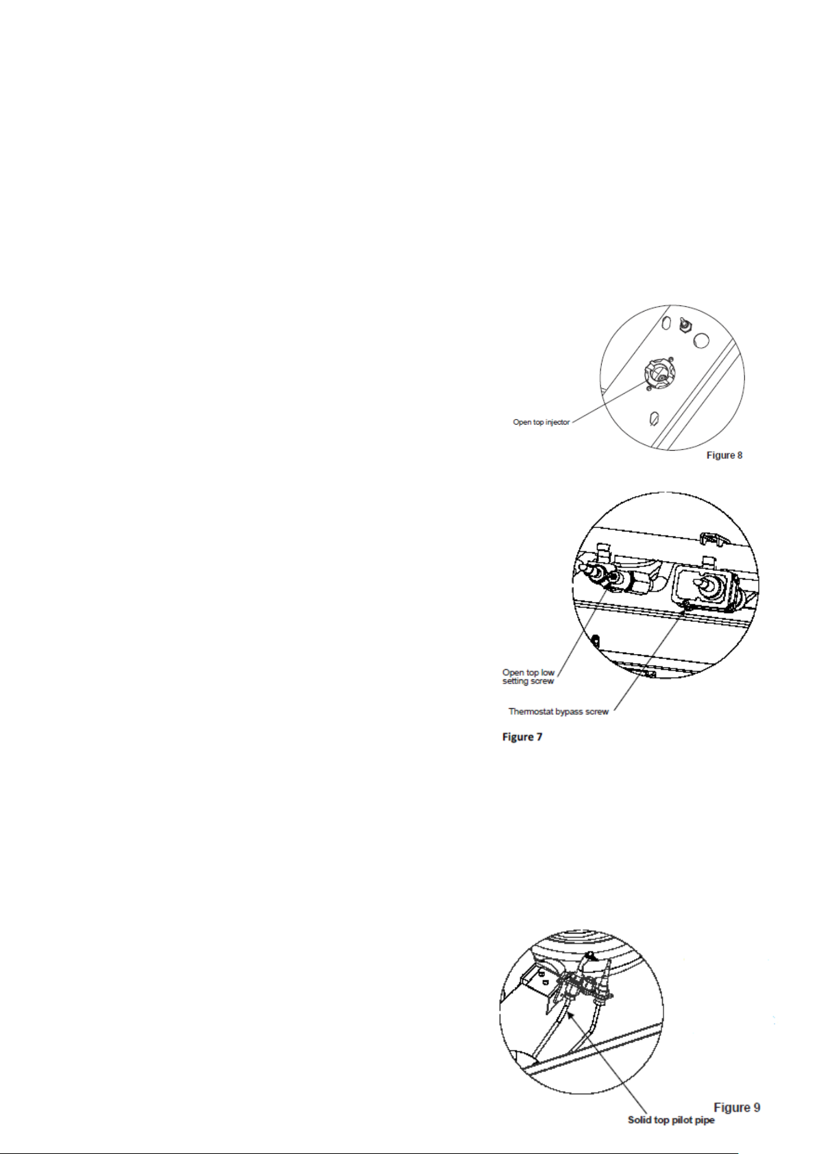
3.1.1 Open Top Burners - To Replace Injector (Figure 8)
a) Remove pan supports.
b) Remove burner heads and burner bezels.
c) Remove pressed hob by pulling upwards.(Do not
remove screws in hob.)
d) Leaving injector holders in situation, unscrew existing
injectors.
e) Remove injectors.
f ) Insert replacement injectors and secure. Repeat for all
taps
g) Refit removed parts.
3.1.2 Open Top Low setting Screw - To Replace (Figure 7)
a) Remove control panel.
b) Unscrew and remove existing low position screw from open
top tap.
c) Insert replacement screw into open top tap and secure.
Repeat for all taps.
d) Refit control panel.
3.1.3 Oven Burner - To Replace Injector
a) Remove oven shelves and base plate.
b) Disconnect Gas supply pipe.
c) Unscrew and remove existing injector.
d) Insert and screw in replacement injector.
e) Re-connect Gas supply pipe.
3.1.4 Thermostat - To Replace Bypass Screw (Figure 7)
a) Remove control panel.
b) Unscrew and remove existing bypass screw from
thermostat.
c) Insert replacement bypass screw and secure into
thermostat.
d) Re-assemble in reverse order.
3.1.5 Solid Top Burner - To Replace Injector (Figure 9)
a) Remove solid top castings.
b) Release pilot assembly from burner.
c) Remove burner.
d) Unscrew and remove existing injector.
e) Insert and screw in replacement injector.
f) Refit burner and ensure burner aeration adjustment.
(see Section 1.10)
Page 9
9
Pilot injector
a
) Remove pilot pipe from pilot assembly.
b) Remove existing pilot injector from pilot pipe.
c) Fit replacement injector over pipe
d) Refit pilot pipe to pilot assembly.
e) Refit pilot assembly to burner.
f) Leave solid top castings off to allow manometer to be fitted to burner test point.
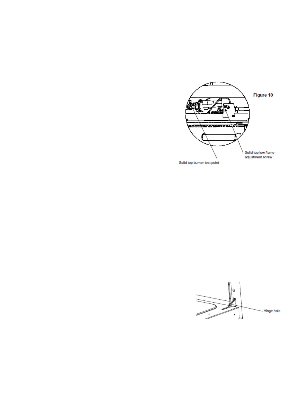
3.1.6 Resetting Low Rate Screw (Figure 10)
a) Remove control panel.
b) Fit manometer to burner test point.
c) Connect replacement gas supply to appliance.
d) Light solid top burner.
e) While burner is ignited turn solid top tap to the
low flame position.
f ) Turn screw until manometer reading is stated
in the table indicated in Section 1.10.2.
g) Refit control panel.
h) Remove manometer from burner test point,
ensuring no gas leaks. Reassemble solid top
castings.
Ensure data plate with correct information is fitted after conversion.
3.2 REMOVAL OF CONTROL PANELS
Various panels are removed as follows:
3.2.1 To Remove Facia Panel
Remove control knob(s). Open oven doors and undo fixings along underside and top. Pull facia
panel forward while slightly easing bottom edge upward to remove.
3.2.2 To Remove Open Top Hob Components
Remove pan supports and burner heads complete with aluminium bezels and venturi that sit
loosely upon injector holder.
The hob is retained by ballstud fixings at each corner. Lift hob clear to access burner support
brackets.
3.2.3 To Remove Hob
Remove fixings that secure front hob support and fixings that secure flue to back panel. Lift full hob
area – including flue – clear of unit.
3.3 REMOVAL OF DROP-DOWN DOOR
Open door completely and insert a suitable pin into
marked hole on both hinges.
The action of closing door will result in the hinge pulling out
of bracket to allow door to be removed.
Due to hinge springs being under tension, do not disturb pins
while door is removed from range.
Replace in reverse order.
Page 10
10
3.4 BURNERS
3.4.1 Open Top
Remove hob components as Section 3.2.2. Undo burner pipe compression fitting.
Undo injector holder fixings. Withdraw burner body.
Replace in reverse order.
3.4.2 Oven
Open oven doors and remove base panel. Undo Gas connection.
Remove tie wrap, pull back insulated sleeving and disconnect
igniter lead at spark electrode end.
Undo FFD thermocouple at burner.
Undo fixings that secure burner feet to base panel.
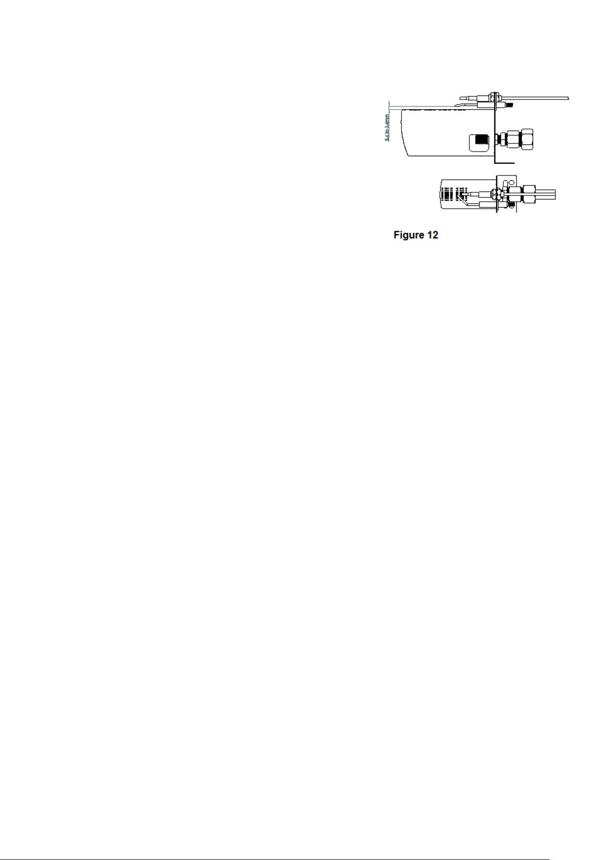
Remove oven burner.
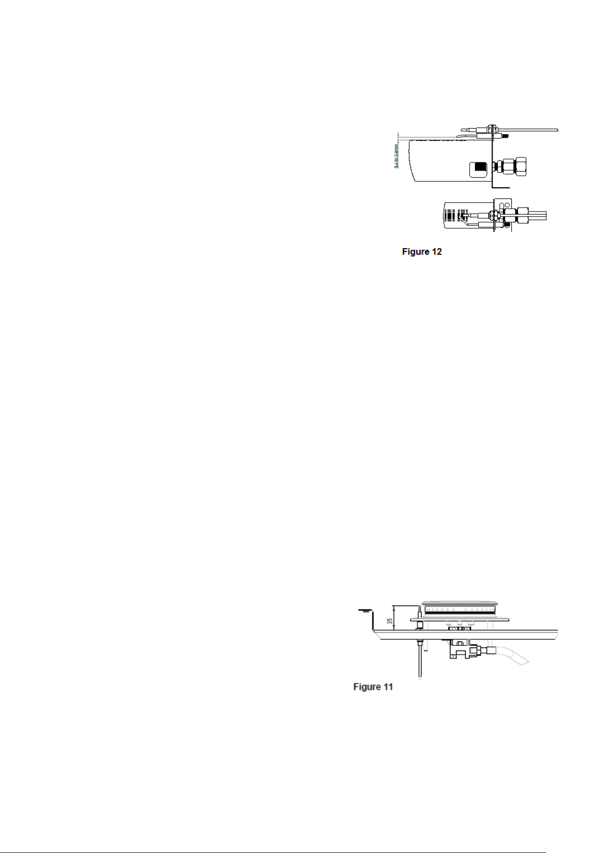
Replace in reverse order, ensuring correct dimensions for Spark
electrode and FFD Thermocouple. (fig 12)
3.5 CLEANING
3.5.1 Burners
Burners should be cleaned daily to maintain maximum performance. Open top burners should
be cleaned as detailed in User Instructions. Additional burners are best cleaned with a wire brush;
port blockage should be freed using a metal broach, any loose material being shaken out via burner
shank.
Ensure burners are dry and free from any cleaning material before replacing.
Check adjustment as detailed in Section 1.
3.5.2 Injectors
Injectors are best cleaned with a wooden splinter or soft fuse wire. Metal reamers may distort or
increase orifice size and their use should be avoided.
3.6 THERMOCOUPLES and FLAME FAILURE DEVICE (FFD)
3.6.1 Open Top Flame Failure Device Magnet Unit
To remove and replace FFD magnet unit, the following procedures must be followed. Isolate Gas
supply.
Remove hob components as detailed in Section 3.2.2. Undo FFD thermocouple at rear of tap, undo FFD
section at tap rear and withdraw.
Replace in reverse order.
3.6.2 Open Top Thermocouple
Remove hob as detailed in Section 3.2.2.
Remove nut that secures thermocouple to burner
support bracket and pull thermocouple through
support bracket from underside.
Undo thermocouple connection at FFD section of gas
tap and carefully remove thermocouple.
Replace in reverse order, taking care to position
tip correctly in relation to burner ports.
Thermocouple tip should be 35mm above
support bracket. Ensure thermocouple does not
touch any part of burner when fully re-assembled. (Fig 11)
3.6.3 Oven Flame Failure Device Magnet Unit
The oven FFD magnet unit is an integral thermostat part. Remove hob components as detailed in
Section 3.2.2 to gain access to FFD. Isolate Gas supply.
Undo FFD thermocouple at thermostat rear. Undo rear FFD section and withdraw. Replace in reverse
order.
Page 11
11
3.6.4 Oven Thermocouple
To Remove Thermocouple
Remove facia panel as detailed in Section 3.2.1. Remove hob fitments. See Sections 3.2.2 or 3.2.3
as required.
Remove RH side panel.
Undo thermocouple nut at thermostat rear.
Open over doors. remove shelves and base plate. Undo nut
that secures thermocouple to burner bracket. Remove
sensor from burner bracket. Release thermocouple from clips
in oven chamber. Remove Thermocouple by feeding through
slot in oven side panel. Replace in reverse order, taking
care not to over tighten, ensure side wall insulation around
thermocouple access slot is undamaged then ensuring
position as indicated in Figure 12.
3.7 OVEN IGNITERS and ELECTRODES
Igniter is piezo spark type and contains no batteries. Unit comprises piezo spark igniter, lead and
electrode assembly. Lead and earth lead are push-fit at igniter end. Oven igniter electrode,
Thermocouple, and burner ports should be aligned as indicated in Figure 12.
3.7.1 Oven Igniter
Remove facia panel as detailed in Section 3.2.1. Disconnect igniter earth wire and .Pull back
insulated sleeve and remove igniter lead connection from spark igniter.Undo nut that secures igniter
in position. Remove Igniter. Replace in reverse order,
3.7.2 Oven Electrode
Remove oven shelves and base plate. Remove tie wraps and pull back insulated
sleeve.
Disconnect igniter lead from electrode.
Undo fixing that secures electrode to burner bracket. Remove electrode and replace in reverse order
ensuring position is as indicated in Figure 12.
Note: Care should be taken not to damage electrode
Important: if spark is present but burner will not light, ensure gas is present and dimensions are as
(Fig 12)
3.8 OVEN THERMOSTAT
Remove control knobs and fascia panel as detailed in Section 3.2.1.
Remove hob fitments as detailed in Sections 3.2.2 and 3.2.3 as appropriate.
Undo thermocouple connection at thermostat rear. Disconnect oven burner pipe.
From inside oven, release clips that secures thermostat capillary to oven side wall. Undo fixings
that secure thermostat to manifold.
Remove thermostat by carefully feeding capillary and phial through crown plate.
Replace all parts in reverse order. Renew manifold gasket if necessary.
3.8.1 Thermostat Calibration
The thermostat should not be calibrated. If temperature is outwith specified tolerances, replace
thermostat and return faulty thermostat to Falcon Quality Department.
3.9 OPEN TOP and SOLID TOP GAS TAPS
Note - Plugs and bodies are machined in pairs and are therefore not interchangeable.
Always clean one tap at a time.
3.9.1 Service - Isolate from gas supply.
Remove control knobs and fascia panel as detailed in Section 3.2.1.
Remove fixings from front of tap body. Withdraw spindle and niting arrangement to allow plug to be
eased out. Clean gas tap plug with a soft rag and regrease using an approved high temperature
lubricant. Take care not to over-grease as surplus may cause gasway blockage.
Replace parts in correct order and check gas tightness.
Page 12

12
3.9.2 Removal – isolate from gas supply.
Remove control knobs and fascia panel as detailed in Section 3.2.1.
Remove hob fitments as detailed in Sections 3.2.2 and 3.2.3 as appropriate.
Disconnect thermocouple connection at gas tap rear.
3.10 GOVERNOR (Natural Gas Models Only)
The governor supplied is maintenance free. Check that blue dust cap is covering vent and in good
condition as this protects the breather hole.
When checking for gas leaks around governor, be aware that unburned gas may be vented
occasionally to release pressure on diaphragm. This should not be confused with a gas leak.
3.11 FAULT CHECK LIST
If a flame is not established on any burners (hob or oven), follow this check list.
1.
Check mains gas is ON.
2.
Check pressure at test point to ensure gas is flowing to unit.
3.
If pressure does not register then check governor is fully operational or check for line blockage.
4.
If gas is present, check burner injector for blockage.
5.
If injector is OK then check FFD is engaging and passing gas.
6.
OVEN ONLY - Check for spark at spark electrode.
7.
OVEN ONLY - If there is no spark then check spark dimensions (fig12) and HT lead
connections. Also check igniter.
8.
OVEN ONLY – Note: Spark may be present but will still not light burner unless dimensions relative to
burner are as Fig 12.
Note: If after adjusting the electrode to the correct dimensions (fig 12), a spark is not present, or is
present but will not light burner, check the following:
Check Spark lead and return earth wire connections at piezo spark igniter body.
Check for clean contact between burner fixing feet and oven base, using spring washers under
screw heads.
9.
If flame is still not present, then re-check from start.
If flame is established but not maintained, follow this check list.
1.
Check thermocouple is positioned correctly in burner flame. (fig 12) Burner ports must be clean.
2.
Check thermocouple is not damaged and is secured to gas valve FFD section to allow FFD to
energise.
3.
Check FFD is energising and maintaining flame.
4.
If, after carrying out the above, burner is still not maintaining flame then re-check from start.
SECTION 4 - SPARES and ACCESSORIES
When ordering spare parts, always quote appliance type and serial number.
This information will be found on data badge attached to base plate.
 Loading...