

Page 1
DOMINATOR
PLUS
GAS RANGE APPLIANCES
USERS INSTRUCTIONS
SECTION 1 - GENERAL DESCRIPTION
SECTION 2 - LIGHTING and OPERATIONS
SECTION 3 - COOKING HINTS
SECTION 4 - CLEANING and MAINTENANCE
These appliances have been UKCA/CE-marked based on compliance with the Gas Appliance Regulations/ Product
Safety and Metrology Regulations for the Countries, Gas Types and Pressures as stated on the data plate.
The appliance MUST BE installed by a competent person in compliance with the INSTALLATION AND SERVICING
INSTRUCTIONS and National Regulations in force at the time. Particular attention MUST be paid to the following:
Gas Safety (Installation & Use) Regulations
Health and Safety at Work Act
Furthermore, if a need arises to convert the appliance for use with another gas, a competent person must be
consulted. Those parts which have been protected by the manufacturer MUST NOT be adjusted by the User.
Users should be conversant with the appropriate provisions of the Fire Precautions Act and the
requirements of the Gas Safety Regulations.
PREVENTATIVE MAINTENANCE CONTACT
To obtain maximum performance from this unit regular servicing of the appliance should be undertaken to ensure
correct operation, it is functioning as intended, and safe to use. We recommend servicing in accordance with
SFG20 Maintenance Schedules and as a minimum, after 2,500 hours of use, or annually, whichever comes first
and that a maintenance contract be arranged with an appointed service contact. Visits may then be made at
agreed intervals to carry out adjustments and repairs.
WARNING - TO PREVENT SHOCKS, ALL APPLIANCES WHETHER GAS OR ELECTRIC, MUST BE EARTHED.
Upon receipt of the User's Instruction manual, the installer must instruct the responsible person(s) of the correct
operation and maintenance of the appliance. This equipment is ONLY FOR PROFESSIONAL USE, and
shall be operated by QUALIFIED persons. It is the responsibility of the Supervisor or equivalent to ensure that
users wear SUITABLE PROTECTIVE CLOTHING and to draw attention to the fact that, some parts will, by
necessity, become VERY HOT and will cause burns if touched accidentally.
WEEE Directive Registration No.
WEE/DC0059TT/PRO At end of unit life, dispose of
appliance and any replacement parts in a safe manner,
via a licensed waste handler.
Units are designed to be dismantled easily and recycling
of all material is encouraged whenever practicable.
Falcon Foodservice Equipment
HEAD OFFICE AND WORKS
Wallace View, Hillfoots Road, Stirling. FK9 5PY. Scotland.
Phone: 01786 455200
T100753 Ref. 9
Page 2

2
Training and Competence
To help ensure the safe use of this appliance there is a requirement for you to provide whatever information,
instruction, training and supervision as is necessary to ensure, so far as is reasonably practicable, the health
and safety of all users.
For further help and information on training and competence we would refer you the Health and Safety
Executive website; www.hse.gov.uk document ref: health and safety training INDG345. International
customers should default to the health and safety guidelines provided by your government body.
Risk Assessment
As part of managing the health and safety of your business you must control any risks identified in your
commercial kitchen. To do this you need to think about what might cause harm to people and decide whether
you are taking reasonable steps to prevent that harm. This is known as risk assessment. It is important to
consider the environment around the product as well as the product itself. For example oil or food spills will
present a significant risk so users so the need to immediately clean up such spills must be reflected in staff
training.
For further help and information on risk assessments we would refer you to you the Health and Safety
Executive website; www.hse.gov.uk document ref: risk assessment INDG163. International customers should
default to the health and safety guidelines provided by your government body.
SECTION 1 - GENERAL DESCRIPTION
This group of products consists of the following models.
G3101 six burner open top range
G3101D six burner open top range
G3107 solid top range
G3107D solid top range
G3117 general purpose oven
G3117 general purpose oven on stand G3117/2 two tier general purpose oven
G3117D general purpose oven
G3117D general purpose oven on stand
G3121 six burner open top boiling top
G3122 two burner open top boiling top
G3124 four burner open top boiling top
G3127 solid top boiling table
G3161 four burner open top range
Units are fitted with flame failure devices to shut off gas supply to burners if flames are extinguished.
The oven is thermostatically controlled.
Controls
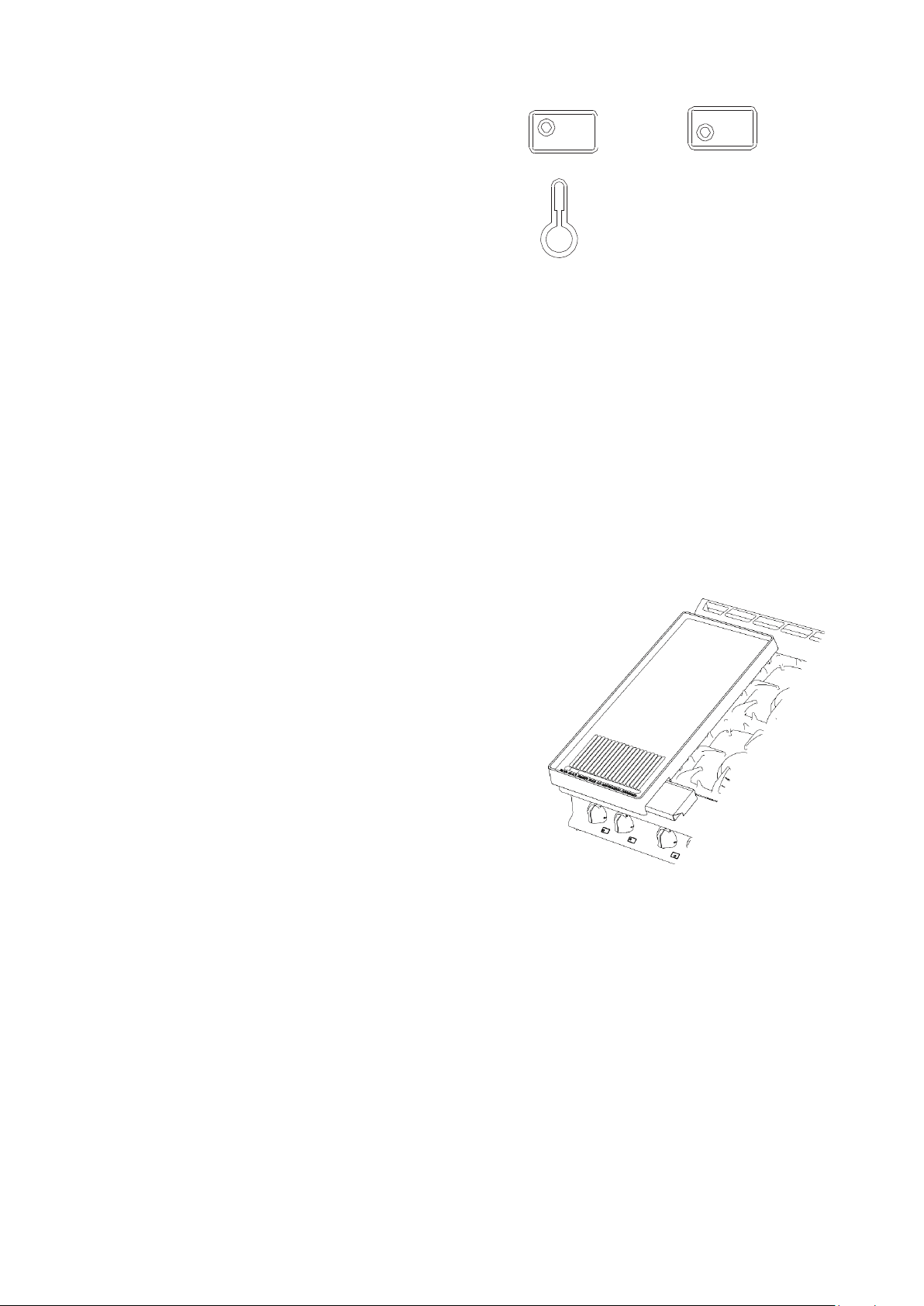
All taps are the safety type with fixed HIGH and LOW settings. The markings are illustrated below.
Open Top Gas Tap Solid Top Gas Tap Oven Gas Tap
Figure 1
Figure 2
Figure 3
Page 3
3
Each tap may be identified with the corresponding burner.
The oven is thermostatically controlled. Control knob
markings are in degrees Celsius and the control is identified
by this symbol.
Note - Spark ignition button is located on control panel.
SECTION 2 - LIGHTING and OPERATIONS
Warning - Never leave products that are being used unsupervised and always turn products off at the end of
service.
Open Top
1.
Ensure mains gas is turned on.
2.
Press and turn knob to full flame position.
3.
Light burner using taper or match and continue to hold knob in for a further 20 seconds before release.
4.
Burner should remain lit; if burner goes out return to Step 1 and repeat ignition procedure.
5.
When burner remains lit, turn knob to required position.
To Shut Open Top Burner OFF
Turn knob to OFF position.
Using the Fryplate Accessory (Figure 6)
Important Note - Caution
This should only ever be used with hob burners on low flame
setting.
The plate locates across any of the 3 banks of front and rear
burners of the pan support casting.
A drain slot is located at plate front and a drainage tray slides
below this from either side.
Allow plate to cool prior to any handling. To remove or replace
fryplate, lift it on and away from desired location as
appropriate.
Solid Top
The solid hotplate is composed of two filling plates, a ring and centre bullseye. A double-ring burner is
located below the hotplate.
1.
Ensure mains gas is turned on.
2.
Remove both bullseye castings from solid top hob.
3.
Turn control anti-clockwise to pilot ignition position and push knob in.
4.
Holding knob in fully, apply taper to pilot and observe pilot lights.
5.
When pilot is lit, continue to hold knob in fully for 20 seconds then release. If pilot is
extinguished, turn control off and wait three minutes. Repeat from Step 3.
6.
Having established pilot condition, turn control knob anti-clockwise to FULL FLAME position. This
will light main burner.
7.
For LOW FLAME operation, turn control knob further anti-clockwise to LOW FLAME position.
8.
Replace bullseye castings.
9.
Minimum temperature of hottest solid top area is 295°C.
Figure 4
Figure 5
Figure 6
Page 4

4
To Shut Solid Top Burner OFF
1.
Turn to pilot position, ready for next operation.
2.
To extinguish completely, turn to OFF position.
Oven
1.
Ensure mains gas is turned on.
2.
Open oven doors.
3.
Turn thermostat knob to maximum setting and push in. This will establish a flow of gas to oven
burner.
4.
Continue to press knob in and at the same time, push piezo ignitor button situated on control panel
to provide a spark at oven burner. Press at 1 sec intervals for 8 times only.
5.
Should burner fail to light, wait 3 minutes then return to Step 2 and repeat ignition procedure.
6.
Having established burner flame, maintain pressure on knob for a further 20 seconds before
release.
7.
Burner should remain lit. Should burner fail to remain lit, wait 3 minutes then return to Step 2
and repeat ignition procedure.
8.
When burner remains lit, turn thermostat to required temperature setting.
To Shut Oven OFF
To extinguish burner, turn thermostat control knob to OFF position.
SECTION 3 - COOKING HINTS
Warning: Caution must be used when opening the oven door when the cooking chamber is hot
Open Top
All open top burners are rated at 5.3kW nett.
The pan supports will safely accommodate pans from 125mm diameter (minimum) to 380mm diameter
(maximum).
It should be noted that it is not advisable to use
6 pans of maximum size as this will impede performance and combustion.
Note - For maximum efficiency, place pan centrally over burner head. Adjust control setting to avoid flames
licking up pan sides.
If using fryplate accessory, this requires to be seasoned prior to use.
Important Note – Caution - Fryplate should only ever be used with hob burners on low flame setting.
Solid Top
It is normal practice to leave burner full on for entire time that hotplate is in use.
As much of the heat is concentrated at the centre, tapering away towards the edges, this area should
be used for rapid boiling. The pan may then be moved away from main heat source to simmer at a desired
intensity.
Hints on Using a Solid Hotplate
Getting the best out of this type of heat source is largely a matter of experience coupled with the needs of
a particular task in hand. For certain applications, such as heating a pot quickly, it will be found expedient to
remove centre ring and place pot
directly over burner. Ring must be in position if it is necessary to heat the entire surface.
In the interests of fuel economy, it is recommended that the solid top is never left unattended at FULL
setting. If it is necessary to keep hob hot for any length of time, control should be turned down to low flame
setting.
NEVER leave gas on without a pot while centre ring is removed - such practice simply wastes gas.
The hottest areas are the centre and toward rear. Front and sides are cooler.
Page 5

5
Models with Drop down Door
Maximum weight to be placed upon door panel when open should never exceed 20kg.
The door should never be used as a step, nor should it be knelt on or sat on.
Oven
Temperature is automatically controlled by thermostat.
Caution: Opening oven door will result in the escape of heated air products. Care should be taken by users
to avoid being burned by any such action.
Grid Shelves
Two cooking shelves are supplied which can be supported in any of five different positions within the oven.
When two shelves are used, these should be positioned with at least one single shelf space between
them. Always push shelves in until stops hit the front of the supports.
Tray Sizes
900mm wide oven will accommodate a 2/1 gastronorm tray. 600mm wide oven will accommodate a 1/1
gastronorm tray. Single trays or dishes should be positioned centrally. Trays must not be allowed to
overhang the shelf in any direction as this will adversely affect heat circulation.
Pre-Heat Time
Allow at least 45 minutes from lighting a cold oven before a full load of food may be cooked. Air temperature
will have reached control setting in 15 minutes. This pre-heat time may be suitable for lighter loads.
Insert food quickly and close doors firmly.
Oven Cooking Chart
This information is provided as guidance only. Figures are approximate and based on a G3101 oven. Due to
the natural heat gradient in this type of oven, it will be necessary to interchange products on upper and
lower shelves during cooking period.
Changeover timing varies according to product type, weight and temperature.
Food Products
Total Quantity
Total Weight
(kg)
Temperature
Setting (ºC)
Runner
Positions
Changeover
Time (mis)
Total Cook
Times (mins)
Vol –au-vents (medium)
80
1.1
230
2&4
10
16
Sultana Scones (½”)
80
4.5
240
2&4 9 14
Croissants (55g)
36 2 200
2&4
12
20
Bread Rolls (75g)
48
3.6
230
2&4
10
17
Quiche Lorraine (8” dia/68g)
12
8.2
195
2&4
35
60
Yorkshire Pudding
72
2.7
240
3&5
18
32
Sponge (slab)
4
5.5
200
2&4
12
24
Baked Jacket Potatoes
72
26.5
220
2&4
70
110
Page 6
6
SECTION 4 - CLEANING and MAINTENANCE
MAINTENANCE CHECK
Regular servicing of the appliance should be undertaken to ensure correct operation, it is functioning as
intended, and safe to use. We recommend servicing after 2,500 hours of use, or annually, whichever comes
first.
Any maintenance schedule should be carried out in accordance with SFG20 Maintenance Schedules. Should
any issues with the integrity of the components be identified these should be replaced. If the appliance is not
considered safe the unit should be removed from service and the responsible person advised why the unit is
not safe to use and what remedial action is needed. Contents of the maintenance schedule should be agreed
with the maintenance provider.
When removing heavy items to aid cleaning or maintenance particular care should be taken. A manual
handling risk assessment is the best way to determine the level of risk to anyone using or maintaining this
equipment. To help with such an evaluation we have included the weights of individual components that may
present significant risk.
For further help and information on manual handling and associated risk assessment we would refer you to
you the Health and Safety Executive website; www.hse.gov.uk document ref: manual handling at work
INDG143. International customers should default to the health and safety guidelines provided by your
government body.
The cleaning of fryers or other products that use hot oil present significant risks to end users and particular
care should be taken. Cold water and hot oil for example are an explosive mix and should be avoided at all
costs.
Other useful references for health and safety issues
www.hse.gov.uk
Essentials of health and safety at work ISBN978
Noise at work INDG362
Safe systems of work
Other notes added to the body of the instructions
All surfaces are easier to clean if spillage is removed before it becomes burnt on and if unit is cleaned daily.
Never clean products that are hot.
Stainless Steel Surfaces
These surfaces should be cleaned with hot water and detergent then dried and polished with a soft cloth.
All spills onto the appliance and on floor should be cleaned up immediately.
Cleaning agents containing bleach, abrasives or caustic chemicals will damage or stain the stainless steel
surfaces and must not be used.
Vitreous Enamel Surfaces
Approved cleaning agents which have the Vitreous Enamel Development Centre (VEDC) mark are
recommended. it is advisable to clean daily after use. Wipe vitreous enamel surfaces clean while they are
still warm using a soft cloth and hot soapy water. Badly stained, removable parts should be soaked in
hot water with an approved detergent. Application of warm water using nylon or scotch cleaning pads with
such detergent will give good results for non-removable parts.
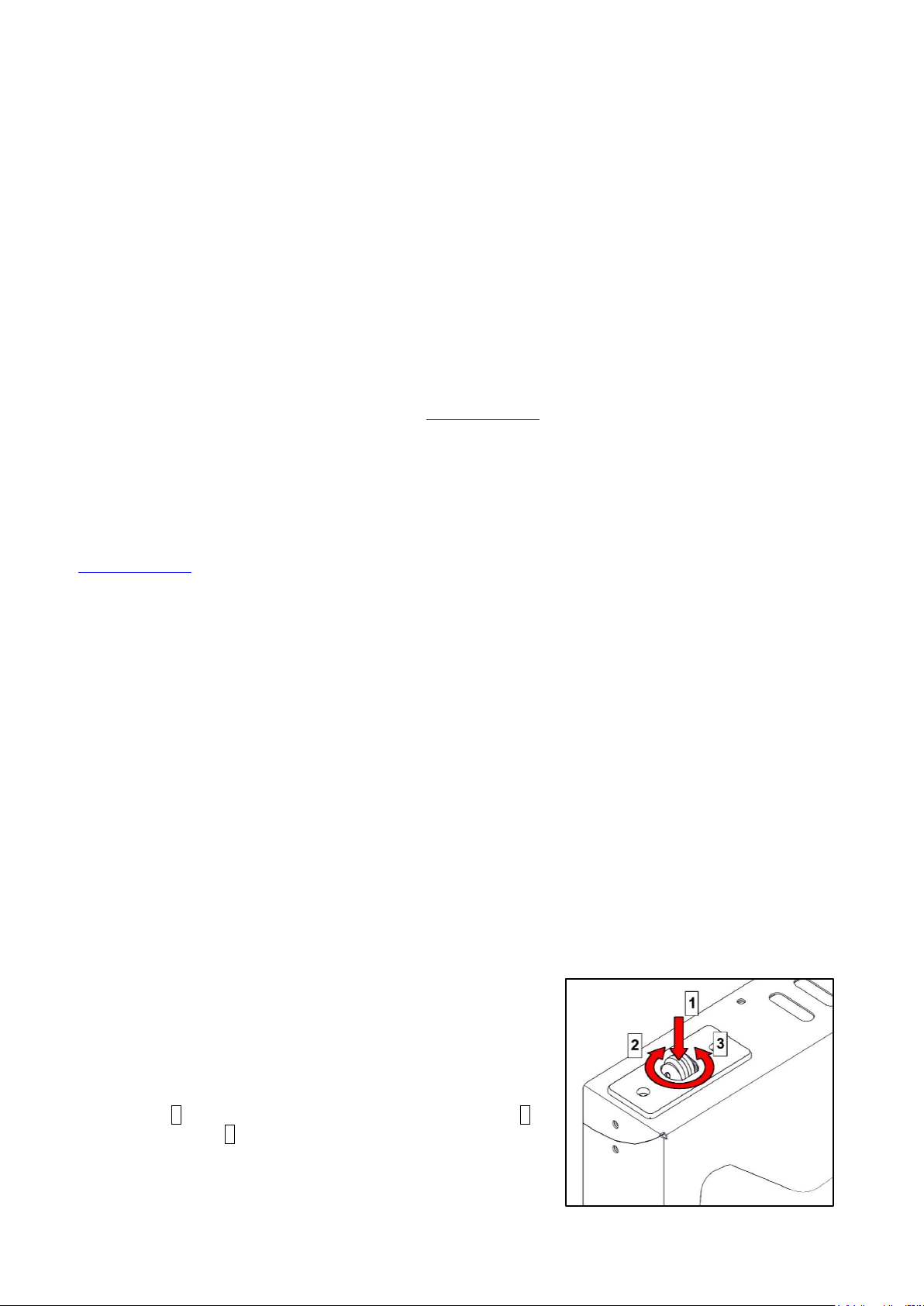
Oven Door Catch
Lubricate door catch occasionally. Push down roller and apply high
melting point lubrication inside the catch and onto the roller itself.
If there are issues with closing of the door, try adjusting the catch
(Fig 7). Use your hands or an appropriate implement to push down
on the roller 1 as shown. Whilst holding it down, turn it right 2 to
adjust it down, or left 3 to adjust it up as shown.
Figure 7 – Door catch adjustment.
Page 7
7
Open Top Burners
Burner cleaning should be carried out daily.
Burner efficiency will be significantly reduced if recommended cleaning is not carried out.
Remove pan supports and open top burner heads.
Wash all parts with hot soapy water according to detailed instructions enclosed at end of section.
After washing, dry all parts well and ensure all water is removed from inside burner head.
Wipe hob area. Hob tray may be lifted off for cleaning purposes and is secured by ball stud fixings at
each corner. To lift away, pull tray up by gripping through burner cut-outs.
Replace parts in reverse order. Ensure that all parts are located correctly. The semi-sealed hob must be
pushed down fully on ball stud fixings.
Dry pan supports by hand. NEVER LEAVE THESE TO DRY NATURALLY.
OVEN
To Clean the Oven
Clean while oven is warm but not hot. The enamelled base plate lifts out and runners can be removed
(grip runner at bottom, pull runner out at bottom holes in side panels. Slide top runner pins out of top holes in sides by
pulling and dropping down).
Take care when removing cast iron items as they are heavy items.
Pan Supports – 5kg
CLEANING INSTRUCTIONS for OPEN TOP BURNERS
The following instructions should be followed when:
a) A spillage has occurred on the burner.
b) The burner fails to light or stay alight.
c) At the end of each day or cooking period.
Caution - Parts will be hot therefore protection to avoid burns should
be used.
Remove pan support.
1.
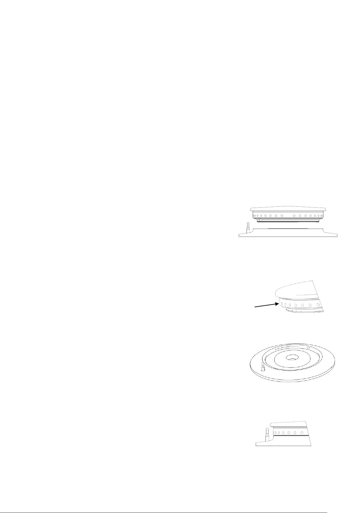
Remove brass burner head and aluminium bezel by lifting
upward.(Figs 8,12).
2.
Thoroughly clean with soap and water. Ensure all burner
ports are clean and free from food or cleaning material
debris.(Fig 9)
Important
Stubborn debris lodged in ports (See Figure 8) can be removed using
a non-metallic implement (ie. cocktail stick). The slots in base should
be freed of debris using a soft brush. Dry burner with a lint-free cloth
and blow through ports to ensure there is no blockage
3.
Clean any spillage from aluminium bezel (Fig 10), ensuring all food
and cleaning material debris is removed. Dry aluminium bezel
thoroughly, taking care not to damage flame sensor. (Fig 11)
Important - Do not allow any spillage or cleaning material debris to enter
the large hole in the aluminium burner bezel. (Fig 10)
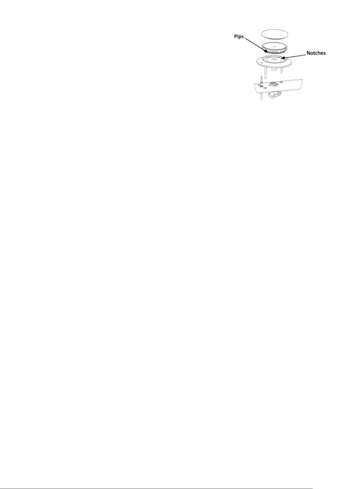
4. Replace burner head and aluminium bezel upon burner base and
ensure b r a s s head location pips sit within aluminium burner
bezel notches.
Figure 8 – Brass burner head and Bezel
Figure 10 – Aluminium Burner Bezel
Figure 11 – Flame Sensor
Ports
Figure 9
Page 8
8
When burner head is properly located, it will not rotate.(Fig12)
5. Light burner to check that it operates correctly.
Note: Parts MUST BE dried thoroughly prior to re-lighting.
Note - Follow this process prior to calling for a Service Engineer
Failure due to lack of proper cleaning is not covered by warranty.
Cleaning the Fryplate Accessory (if used)
Do not use abrasives or sharp tools on surface of plate.
Wash with warm soapy water, do not use caustic chemical cleaning products.
Do not allow to dry naturally, dry with a towel or cloth.
SECTION 5 - SPARE PARTS
The following parts may require replacing during the life of this appliance.
Control valve
Rear thermocouple
Front thermocouple
Oven thermostat
Oven thermocouple
Note: Thermostat is supplied as standard with a natural gas bypass screw. When replacing this component
on propane models, the bypass screw needs to be removed from faulty control to be replaced.
Figure 12
 Loading...