

Page 1

*ININST.1019*
1490 EL Baseplate assembly
Left Hand Reverse
Right Hand Reverse
EL1490
ININST.1019
Panic Exit Device Baseplate Retrot
(For EL1590 applications, see opposite side of instruction sheet)
Parts List
Installation Instructions
Kit.1011
Baseplate assembly for:
36” and 42” device
Kit.1013
Baseplate assembly for:
48” device
• Verify length and handing of new baseplate assembly matches old baseplate assembly before proceeding with disassembly.
• If the device you are replacing has been cut to a non-standard length, refer to device instruction for cut length to determine if new
retrot baseplate assembly will t (new baseplate may be slightly longer than old baseplate).
• If existing application, disconnect power source before working on device.
• Consult factory if you are attempting to retrot 1490 device that originally was not electried.
1 Remove device from door
1a Remove pushbar end cap on hinge
stile.
1b Loosen two mounting screws on
channel mounting plate.
1c Remove pushbar end cap on lock
stile.
1d Remove two mounting screws on
lock stile and remove device from
door.
Kit.1010
Baseplate assembly for:
36” and 42” device
Kit.1012
Baseplate assembly for:
48” device
Notes
Channel
end cap
Channel mounting plate
Channel end cap
Pushbar
end cap
Pushbar
2 Remove channel from old baseplate
2a Place pushbar face down on non-
marring surface.
2b Remove ve exposed screws (one
shorter) from back of channel.
2c Slide channel from device.
Channel slides out
hinge stile of device
Pushbar
end cap
Shorter screw
Page 2
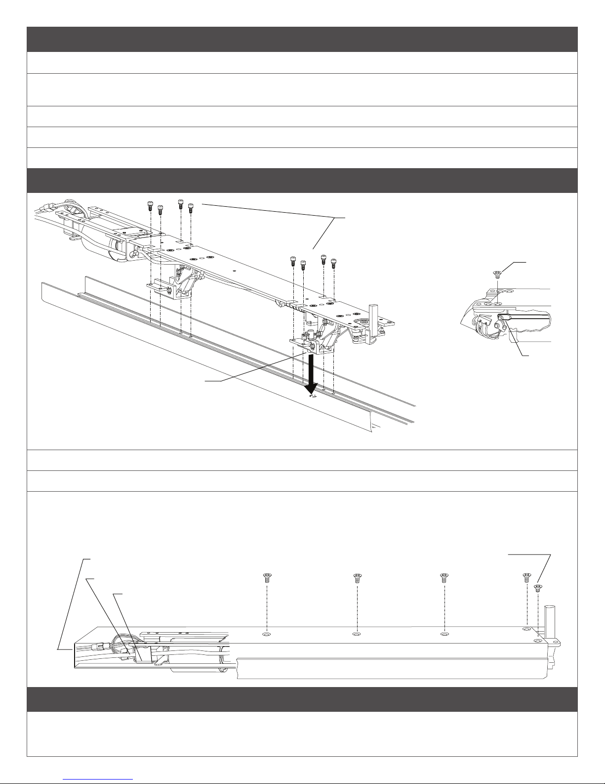
3 Remove pushbar and replace on new baseplate assembly
3a Remove eight clevis mounting screws using a magnetized #2 phillips screwdriver.
3b Remove old baseplate assembly from pushbar.
Verify length (clevis to clevis) of old baseplate assembly matches new one.
3c Place new baseplate assembly on pushbar.
3d Align dogging post on clevis with dogging hole in pushbar.
3e Install eight clevis mounting screws using a magnetized #2 phillips screwdriver.
4 Reinstall channel
Clevis mounting screws
Make sure all lock
washers are installed
on screws
Shorter
screw
Align dogging post on clevis
with dogging hole in pushbar
4a Slide channel onto new baseplate assembly.
4b Verify that wires and ears stay inside channel (see picture).
4c Install ve channel mounting screws (1 screw shorter than the others).
4d Verify pushbar moves up and down freely without binding. If binds, check that:
• Short channel screw is in correct position.
• All wires are routed inside channel.
• Ears of solenoid bracket are inside channel.
All wires contained inside channel
Gray cable routed inside PCB bracket
Ears of solenoid bracket
inside channel
Make sure shorter screw is installed in correct hole
(on bottom side of device when device is mounted)
Rod end
Figure 4-1
5 Reinstall Device
See device instructions for wiring and installation. For old applications wire size to the power supply may need to be increased. Solenoid
wiring must be 12 AWG, 200 feet maximum, between power supply and EL device.
Page 3

EL1590
EL1590 Baseplate assembly
Panic Exit Device Baseplate Retrot
(For EL1490 applications, see opposite side of instruction sheet)
Installation Instructions
Parts List
Kit.1008
Baseplate assembly for:
36” and 42” device
Kit.1009
Baseplate assembly for:
48” device
Notes
• Verify length of new baseplate assembly matches old baseplate assembly before proceeding with disassembly.
• If the device you are replacing has been cut to a non-standard length, refer to device instruction for cut length to determine if new
retrot baseplate assembly will t (new baseplate may be slightly longer than old baseplate).
• If existing application, disconnect power source before working on device.
1 Remove device from door
1a Remove pushbar end cap on
hinge stile.
Channel mounting plate
Channel end cap
1b Loosen two mounting screws
on channel mounting plate.
1c Remove latch bolt housing on
lock stile.
1d Remove two mounting screws
on lock stile and remove
device from door.
2 Remove channel from old
baseplate
2a Place pushbar face down on
non-marring surface.
2b Remove
seven
exposed
screws from
back of
channel.
2c Slide
channel from
device.
Pushbar
end cap
Latchbolt
housing
Pushbar
assembly
Note location of
shorter screw
Channel slides out
hinge stile of device
Page 4

3 Remove pushbar and replace on new baseplate assembly
3a Remove eight clevis mounting screws using a magnetized #2 phillips screwdriver.
3b Remove old baseplate assembly from pushbar.
Verify length (clevis to clevis) of old baseplate assembly matches new one.
3c Place new baseplate assembly on pushbar.
3d Align dogging post on clevis with dogging hole in pushbar.
3e Install eight clevis mounting screws using a magnetized #2 phillips screwdriver. Re
Clevis mounting screws
Make sure all lock
washers are installed
on screws
Align dogging post on clevis
with dogging hole in pushbar
4 Reinstall channel
4a Slide channel onto new baseplate assembly.
4b Verify that wires and ears stay inside channel.
4c Install one shorter screw in the hole below rod end (Figure 4-1).
4d Install other six channel mounting screws.
4e Verify pushbar moves up and down freely without binding.
If it binds, check that:
• Short channel screw is in correct position.
• All wires are routed inside channel.
• Ears of solenoid bracket are inside channel.
Reinstall Device
All wires contained inside channel
Gray cable routed inside PCB bracket
Ears of solenoid bracket
inside channel
5 Reinstall device
See device instructions for wiring and installation. For old applications wire size to the power supply may need to be increased. Solenoid
wiring must be 12 AWG, 200 feet maximum, between power supply and EL device.
Customer Service
1-877-671-7011 www.allegion.com/us
© Allegion 2014
Printed in U.S.A.
ININST.1019 Rev. 06/14-c
 Loading...