

Page 1
OWNER'S OPERATING MANUAL
FREQUENCY CONVERTER &
UNINTERRUPTIBLE POWER SYSTEM
FOR MODELS:
ED3000-A
ED4000-A
The information contained herein is the property of FALCON
purpose provided. OMED3-4K-LC 05-7-04 Rev. A
FALCON®ELECTRIC INC.
5106 Azusa Canyon Road
Irwindale, CA 91706
Tel. 626-962-7770
Fax. 626 962-7720
®
ELECTRIC INC., is proprietary, confidential, and not to be disclosed, disseminated or used except for the
Page 2

TABLE OF CONTENTS
Important Safety Instructions (READ FIRST) . . 1
Chapter 1, ED Series Overview . . . . . 2
Input/Output Specifications Table. . . . 2
Block Diagram . . . . . . 3
Chapter 2, Installation . . . . . . 4
Inspecting the Equipment . . . . 4
Unit Setup . . . . . . . 4
Chapter 3, Controls, Displays & Functions . . . 5
Front Panel Diagram & Description . . . 5
Front Panel LED Functions . . . . 5
Rear Panel Diagram & Description . . . 6
Chapter 4, Communications Interface. . . . 7
Signals & Interfacing . . . . . 7
Chapter 5, Operation . . . . . . 8
Step By Step Operating Procedure . . . 8
Operational Mode Table . . . . . 9
Chapter 6, Maintenance & Technical Support . . 10
Care & Maintenance . . . . . 10
Battery Life vs. Temperature . . . . 10
Battery Replacement . . . . . 10
Storing the UPS and Batteries . . . . 11
FCC . . . . . . . 11
Technical Support & RMA Procedure . . . 12
Requesting Technical Information or Support. . 12
FALCON Web Support . . . . . 12
Brochure . . . . . . . 13
Specifications . . . . . . 14
Page 3

IMPORTANT SAFETY INSTRUCTIONS
SAVE THESE INSTRUCTIONS
This manual contains important instructions which must be followed during the
installation, operation and maintenance of this unit and its battery options. Please
read all instructions before operating this equipment and save this manual for future
reference.
CAUTION
All of the models presented herein are designed for installation and use in a controlled environment free of contamination.
CAUTION
This UPS utilizes voltage that may be hazardous. Do not attempt to disassemble.
This unit contains no user replaceable parts. Refer all servicing to Falcon Electric,
Inc.
CAUTION
This unit is not intended to be used in conjunction with life support or operating
room equipment.
CAUTION
Always unplug this device prior to cleaning and never apply liquid or spray
detergent on the ED unit.
CAUTION
Never attempt to service batteries. High voltage exists within the unit, which could
cause electrical shock. Servicing of batteries should be performed or supervised
by personnel knowledgeable of batteries and the required precautions. Keep unauthorized personnel away from batteries. When replacing the optional ED batteries,
use the same number and type of batteries.
IMPORTANT
If configured with batteries, allow at least 24 hours, after the ED is first installed and
turned on, to fully charge the internal battery and assure the maximum backup time
is available.
DO NOT plug this unit into its own output as this may damage the ED electronics.
DO NOT remove or unplug the input cord when the ED is turned on. This removes
the safety ground from the unit and the equipment connected to the ED.
DO NOT
CAUTION
When configured with optional batteries, the ED contains its own energy
source (batteries). The output receptacles may carry live voltage even when
the UPS is not connected to an AC source.
1
Page 4

CHAPTER 1
CHAPTER 1
ED Series - Overview
Congratulations! You have selected the ED Series Frequency Converter,
Voltage Regulator and UPS. The FALCON®ED Series UPS offers a quiet and
compact package with proven performance you can depend on.
This User’s Guide is provided with your new ED unit. It will enhance your
understanding of the product and its functions. Read this guide carefully in
the order it is presented prior to operating your unit. This will save you time and
effort in your installation and application. The illustrations will also familiarize
you with the ED's operating modes and indications. Always operate the unit
within the guidelines and specifications given to maximize the unit's efficiency
and lifetime. Also, your understanding of the product is essential in providing
you years of service for your back-up power requirements.
Refer to the table below to verify the input and output rating for your model.
INPUT/OUTPUT SPECIFICATIONS
MODEL INPUT OUTPUT OUTPUT
POWER
ED3000-A 120Vac, 47-420Hz 120Vac, 50 or 60Hz 2100 Watts
ED3000-A 120Vac, 47-420Hz 120Vac, 400Hz 1785 Watts
ED4000-A 120Vac, 47-420Hz 120Vac, 50 or 60Hz 2800 Watts
ED4000-A 120Vac, 47-420Hz 120Vac, 400Hz 2380 Watts
The FALCON®ED Series represents one of the smallest and most compact
units of the FALCON®Frequency Converter and Uninterruptible Power Supply
(UPS) product line. In the tradition of all FALCON®products, it maintains the
highest reliability and the most complete on-line, sinewave power conversion
and protection available. An on-line, sinewave converter is the only solution to
AC line frequency conversion. With the addition of an optional external battery
bank the ED models referenced in this manual will also provide true on-line UPS
battery backup. There is no break, transient or glitch in source transfer during a
power failure because THERE IS NO TRANSFER.
The FALCON®ED SERIES is engineered with the latest MOSFET/PWM
technology for high efficiency and reliability.
2
Page 5
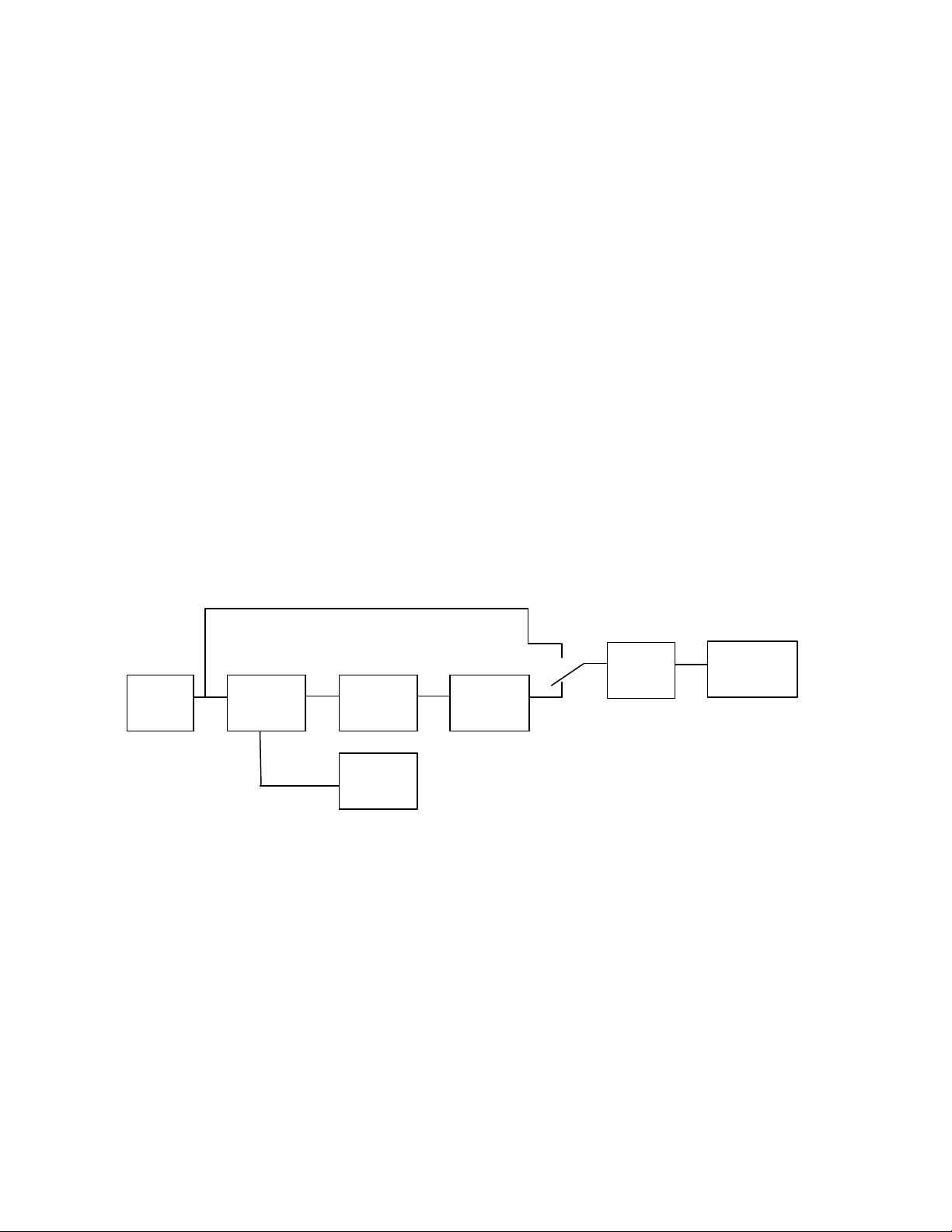
Refer to the simplified block diagram, Figure 1, for a system description. The
EMERGENCY
EMERGENCY
AC source is rectified and provides energy for the DC + Choppers and a float
charge to the optional standby Battery. These DC Choppers then supply the
power to operate the DC/AC Inverter. The inverter provides a new clean
sinewave output at the factory configured output frequency.
When configured with an optional battery bank and during a utility power-loss,
the AC rectification and battery charging capabilities of the UPS become
inactive. The fully-charged battery, however, supplies the necessary power
requirement to maintain the remaining system blocks.
The FALCON®ED on-line topology is unique to other on-line systems, in that, it
is designed to meet the needs of non-linear loads. Equipment, configured with
a switching power supply, is considered a non-linear load which can be very
abusive to most power conversion and protection equipment, and could
decrease its life-expectancy. The FALCON®ED unit is specially designed to
accept these loads and protect them efficiently with minimal of the output
waveform degradation.
For ED models configured with batteries, please refer again to the figure below,
you will notice a built-in safeguard. If the unit has not been configured as a
frequency converter, when it inadvertently experiences an extreme over
temperature situation that causes inverter malfunction, it will switch over to a
filtered emergency bypass line to insure
INPUT
FILTER
FIGURE 1: FALCON ED SERIES BLOCK DIAGRAM
BYPASS LINE
RECTIFIER
CHARGER
+ DC
CHOPPERS
STANDBY
BATTERY
DC/AC
INVERTER
BYPASS
SWITCH
Emergency bypass functions have been disabled
in all ED models configured for frequency
converter operation.
OUTPUT
FILTER
COMPUTER
(LOAD)
3
Page 6

CHAPTER 2
CHAPTER 2
Installation
Inspecting the Equipment
If any FALCON®equipment has been damaged during shipment, keep
the shipping cartons and packing materials for the carrier and file a
claim for shipping damage. If you discover damage after acceptance,
file a claim for concealed damage.
To file a claim for shipping damage or concealed damage: 1) File with
the carrier within 15 days of receipt of the equipment; 2) Send a copy
of the damage claim within 15 days to the Falcon®Service Department.
ED Setup
1. Verify that the following is included in the ED shipping carton:
ED Frequency Converter & UPS, Owner's Guide.
2. Verify that the ED unit is configured for the proper input/output
voltage. This information is stated on the nameplate label located on
the rear panel of the unit.
3. Select a suitable location for the ED, near enough to the computer or
equipment to allow connection of the equipment power plugs to the
receptacles located on the rear panel of the ED.
4. DO NOT BLOCK UPS AIR VENTS. THE UPS MUST NOT BE
INSTALLED IN AN ENCLOSED AREA.
5. Connect the equipment to be powered to the ED output receptacles
located on the rear panel. Verify that the connected equipment does
not exceed the rated output (in watts) of the ED Series unit
IMPORTANT
This ED model is designed for input and output hardwire connections. Two
conduit connector holes are provided on the lower portion of the rear panel.
The hardwire terminal block is located inside the ED unit and can be
accessed by removing the (16) screws securing the units top cover. Remove
the top cover: the terminal block is located on the upper left side of the units
center panel. Pay special attention to the ED input voltage configuration and
verify the input voltage is correct prior to hardwiring the unit. Make the input
and output connections per the picture below.
USE COPPER WIRE ONLY.
4
Page 7

CHAPTER 3
FULL LOAD
OVERLOAD
ALARM INVERTER ON
3 4 1
2
5
CHAPTER 3
Controls, Displays & Functions
AC LINE
75% LOAD
50% LOAD
LOW BATT.
1. AC- AC LINE INDICATOR
This green LED turns on when the AC source is present.
2. INV- INVERTER OPERATING
The LED turns green when the ED inverter is turned on. This LED
normally turns on a few seconds after the AC line indicator LED and
remains on during both utility and battery operation.
3. ALM- ALARM STATUS INDICATOR
This red LED turns on and a continuous audible alarm is sounded when
the ED is overloaded or has failed. Should this occur, check the load
level and correct any overload condition if present. Should the unit not be
overloaded, call FALCON®support for further assistance.
4. LOW BATT.- LOW BATTERY WARNING INDICATOR
The red LED will turn on when the ED is configured with an optional
external battery bank , operating in battery mode and the low battery
level warning point has be reached. Typically one minute of battery run
time remains after the LED turns on.
5. OVERLOAD/ FULL LOAD/ 75% LOAD/ 50% LOAD-
Adjacent to the red low battery LED is the green 50% load LED.
Adjacent to the green 50% load LED is the green 75% load LED.
Adjacent to the green 75% load LED is the yellow 100% load LED.
Adjacent to the yellow 100% LED is the red overload LED. All overload
conditions must be corrected immediately.
NOTE: Reference page 10 for more details
5
Page 8

TYPICAL ED3000 & ED4000 REAR PANEL LAYOUT
9
6
8
7
10
11
6. DB-9F COMMUNICATIONS INTERFACE
This connector gives access to the ED contact closure status interface.
Please reference page 7 of this manual for details.
7. Hardwire conduit connector mounting holes for input and output wiring.
8. COOLING FANS (4)
Cooling fans draw cool air from the outside of the rear panel and
exhaust it out through slots in the ED front panel. ALWAYS KEEP
COOLING FAN AND FRONT PANEL VENTS CLEAR OF DEBRIS. DO
NOT OPERATE THE ED IN AN ENCLOSED SPACE.
9. MAIN POWER SWITCH
To turn on this unit, toggle this switch to the on or (1) position. To turn off
this unit, toggle this switch to the off or (0) position.
10. INPUT FUSE
Always replace this fuse with the same type and rating. The fuse is a
Bussman, KTK-R-30, 30 Amp fuse.
11. Battery Connector (72Vdc)
This connector may be connected to an optional external battery bank,
allowing the unit to be used as a UPS in addition to it’s normal frequency
conversion functions. The ED unit has been configured from the factory
with an internal battery charger. This unit is field upgradable.
Contact the factory for details.
6
Page 9

CHAPTER 4
CHAPTER 4
DB-9 COMMUNICATIONS INTERFACE
7
Page 10

OPERATION
The FALCON®ED unit is very simple to use.
1. Verify the unit is connected to the correct voltage power source.
2. Activate the power switch to the "ON" position.
3. The green AC LED illuminates.
4. The green INV LED illuminates.
5. For frequency conversion models, verify the output frequency is
6. For models supplied with optional battery banks, leave the power
7. The green AC LED will shut off.
8. An intermittent audible alarm will sound.
The system will continue to operate. If this were to continue long
enough, the red LOW BATTERY light would illuminate, indicating that
battery back-up time is ending and system shutdown is imminent. The
intermittent alarm will become continuous at this point. The ED unit will
automatically shut itself off to avoid excessive battery discharge. When
power returns, normal operation of the UPS resumes without any
operator adjustment.
CHAPTER 5
CHAPTER 5
set to the desired frequency using a frequency meter. Disregard
the following steps 6-11.
switch "ON" and open the input circuit breaker at the utility panel,
This will simulate a power loss & test battery operation.
The duration of actual battery back-up time and the low battery condition
varies depending on the amount of load, charge on the battery, and
condition of the battery. Refer to the ED SPECIFICATIONS for
approximate hold-up times at 100% and 50% loads.
9. Reset the input circuit breaker and turn the power switch "OFF".
10. Turn off the devices you wish to plug into the ED. Plug them into
the outlets located on the rear of the ED.
11. Activate the ED unit power switch to the "ON" position.
12. Turn "ON" each of your devices.
13. Some of the LOAD indicators may illuminate. The amount of load
determines the actual number of indicators lit.
The bottom green L.E.D. signifies approximately 50% of load
capacity. The second green L.E.D. represents approximately 75%
of load capacity. If the yellow L.E.D. illuminates, full load has been
achieved. If the red light illuminates, an OVERLOAD condition is
present. If this situation continues for about 15 seconds, the unit
will automatically shut off.
If the system overheats or the Inverter should fail, the unit
automatically shuts off and sounds a continuous alarm and the red
ALM light will illuminate.
8
Page 11

To escape this condition, the problem must first be corrected then
turn the ED power switch "OFF", then back "ON".
For models supplied with batteries it is recommended that you
leave the ED unit power switch "ON" at all times and switch your
devices "OFF" individually. This will ensure that your batteries are
always at a maximum charged state.
WARNING
The power switch acts as a system ON/OFF switch. When this switch is
turned "OFF", power is lost to the entire unit including all outlets at the
rear of the ED.
9
Page 12

CHAPTER 6
CHAPTER 6
Maintenance & Technical Support
1. Care & Maintenance
Falcon®ED Series are designed to be maintenance-free.
They can be cleaned with a damp cloth or non-abrasive cleanser, providing the
ED is turned off and the input plug is disconnected from the utility source.
On a regular basis, check the vents to make sure they are kept free from
accumulation of dust, dirt or lint.
2. Battery Life vs. Temperature (Units supplied with batteries only)
For full battery life, keep the ED close to an ambient temperature of 77ºF.
The batteries should never be exposed to temperatures below 40ºF and above
104ºF
.
3. Battery Replacement (Units supplied with batteries only)
This unit contains sealed maintenance-free batteries (VRLA). When situated in
a typical office environment, with the proper charging and limited cycling, these
batteries can last many years. We recommend that the batteries be replaced
every three years.
WARNING
Never attempt to service batteries. High voltage exists within the unit, which
could cause electrical shock. Servicing of batteries should be performed or
supervised by personnel knowledgeable of batteries and the required
precautions. Keep unauthorized personnel away from batteries.
When replacing the ED batteries, use the same number and type of batteries.
NEVER
A. NEVER dispose of batteries in a fire, as batteries will explode.
B. NEVER dispose of used batteries or the UPS in the trash or landfill as it is
against federal and state laws. The ED and Batteries must be recycled.
For battery recycling information, please contact our service department for
the name and address of the nearest battery recycling facility.
C. Spent batteries must be recycled in accordance with all Federal, State
and local laws. To locate a recycling center near you contact the Falcon
service department.
CAUTION
A. Do not open or mutilate the battery or batteries. Released electrolyte is
harmful to the skin and eyes. It may be toxic.
B. A battery can present a risk of electrical shock and high short circuit current.
REFER ALL BATTERY SERVICING OR REPLACEMENT TO A QUALIFIED
SERVICE TECHNICIAN. UNTRAINED PERSONNEL SHOULD NEVER
ATTEMPT BATTERY REPLACEMENT.
10
Page 13

The following precautions should be observed by a qualified technician when
working with batteries.
1. Remove watches, rings, or other metal objects.
2. Use tools with insulated handles.
3. Wear rubber gloves and boots.
4. Do not lay tools or metal parts on top of batteries.
4. Storing the ED unit
Should you need to store the ED for a long period, if supplied with batteries,
fully recharge the battery just prior to storage and recharge the battery every 6
months by plugging the ED into a power outlet and turning the unit on.
It is recommended that the batteries charge for 24 hours after long-term
storage.
5. FCC
This equipment generates and uses radio frequency energy and if not installed
and used properly in strict accordance with the manufacturer's instructions,
may cause interference to radio and television reception. All models covered in
this manual have been tested and found to comply with the limits for a Class A
computing device, in accordance with the specifications in FCC regulations,
Part 15, Subpart J, which are designed to provide reasonable protection
against such interference.
If this equipment does cause harmful interference to radio or television
reception, which can be determined by turning the equipment off and on, the
user is encouraged to try to correct the interference by one or more of the
following measures:
a. Reorient or relocate the receiving antenna.
b. Increase the separation between the equipment and the receiver.
c. Connect the equipment into an outlet on a circuit different from that to
which the receiver is connected.
d. Consult the dealer or an experienced radio/television technician for
assistance.
11
Page 14

6. Technical Support
Your FALCON®Electric ED Series is backed by one of the finest customer
service teams assembled. Write, Call, Fax or Email should you require
technical assistance or service.
Should service be desired, you must first obtain a Return Material Authorization
number (RMA) and return shipping instructions from our customer service
department. Please have your ED model, serial numbers and date of
purchase on hand prior to the call. This information is located on the
identification label on the rear panel of the unit. This information is essential in
retrieving your unit's historical records.
FALCON ELECTRIC, INC.
5106 Azusa Canyon Road
Irwindale, CA. 91706
Voice 626.962.7770
Fax 626.962.7720
Service 800.842.6940
Email: service@falconups.com
WWW.FALCONUPS.COM
The RMA number issued must appear on the outside of the shipping carton.
The original shipping container must be used when returning any ED
Series product. Falcon®Electric will not assume any responsibility for shipping
damage. In the event of shipping damage, you will be charged for repairs due
to the damage.
All units must be returned prepaid. The address and shipping instructions will
be given to you at the time the RMA is issued.
7. Requesting Technical Information or Support.
You may request technical information or support by Email or telephone.
Please send your technical or support questions by Email to:
SUPPORT@FALCONUPS.COM
You may contact a FALCON support engineer directly by calling the FALCON
support line between 9:00 am and 4:00 pm PST.
800-842-6940
8. FALCON Web Support
Product data sheets, specification and owner’s guides are available in Adobe
.PDF format on our corporate website.
WWW.FALCONUPS.COM
12
Page 15

Uninterruptible Power Systems
& Power Conversion Products
ED Series
UVS PLUS
Voltage & Frequency Converters
True Double Conversion Design
Precision Output Voltage & Frequency
Pure Sinewave Output
Wide Input Frequency Range
50, 60 & 400Hz Frequency Conversion
Voltage Conversion Models Available
Eliminates Generator Frequency & Voltage Drift
Superior Brownout, Surge and Transient Protection
Battery Backed Up Models Available
Technology Breakthrough
Falcon®Electric's ED SeriesTMUVS Plus®is more than
an international voltage/frequency converter, voltage
regulator or line conditioner. Its unique features will
significantly improve your equipment's reliability, virtually
eliminating power-related downtime and dramatically
increasing productivity. Its small size and lightweight
construction makes it ideal for OEM and integrated
applications.
Unique Frequency Converter & UPS Capability
The ED Series provides unique flexibility in a small
footprint. The ED Series can be factory configured as a
pure frequency converter accepting a 50, 60 & 400Hz input
and yielding a fixed 50 or 60Hz output. It can also supply a
400Hz, 120V output if properly derated. The ED can be
configured as an international converter, making it an ideal
solution for those tough applications requiring both voltage
and frequency conversions. A battery system may be
added to most models, turning it into a true Regenerative
On-line UPS.
Superior Voltage/Frequency Regulation &
Extended Brownout Protection
Since the ED Series is a solid-state generator, it prevents
daily power disturbances from reaching your equipment.
Constant voltage transformers, line conditioners and other
devices are not designed to prevent damage from these
problems.
TM
®
1kVA to 4kVA
The ED continually regenerates new, clean AC power in
pure sinewave form for superior protection. Even with wide
input variations in voltage and frequency, the ED Series
UVS Plus's output steadfastly remains at its designed
voltage and frequency. It also allows your system to
continuously operate during extended brownouts to 88 VAC.
Enhanced Surge Start-up Capability
Falcon Electric's ED Series is designed to start loads that
exhibit up to 1000% inrush current when started from utility.
This gives the ED the ability to start tough loads such as
motors, multiple computers or incandescent lighting.
Converts Generator Output Into Computer-Grade
Power
Due to its Regenerative On-line design, the ED Series
regenerates new, clean computer-grade power with tightly
regulated voltage and frequency, independent of generator
voltage and frequency drift.
Ideal for applications such as:
Military & Aerospace
Aircraft Frequency Conversion
Off Shore Platforms
Shipboard Systems
Robotics
Automated Manufacturing
Test Equipment Benches
Precision Motor Speed Application
Mobile Office/Labs
Communications/Microwave
Falcon Electric, Inc. - 5106 Azusa Canyon Rd. - Irwindale, CA 91706 - 800.842.6940 Fax 626.962.7720
www.falconups.com - email: sales@falconups.com
13
Page 16

ED Series
TM
UVS PLUS
®
Model -A
ED Series Model -A Frequency Converter (120V Input/Output)
Model Number ED-1000-A ED-1500-A ED-2000-A ED-3000-A ED-4000-A
Nominal VA 1000 1500 2000 3000 4000
Electrical Input
AC Voltage, +10% -20% 120V 120V 120V 120V 120V
Current-Amps 10.4 15.6 20.8 29 39
Frequency Range 47 – 450 47 - 450 47 - 450 47 - 450 47 - 450
Electrical Output
AC Voltage, ± 3% 120V 120V 120V 120V 120V
Watts @ 50 or 60 Hz 700 1050 1400 2100 2800
Watts @ 400 Hz (-400 option) 595 892 1190 1785 2380
Current-Amps @ 50/60 Hz 8.3 12.5 16.7 25 33
Current-Amps @ 400Hz 7.1 10.6 14.2 21.3 28
50/60 Hz Non – Linear
Repetitive Peak (Amps)
400 Hz Non – Linear
Repetitive Peak (Amps)
Total Harmonic Distortion < 3% @ 100% Linear Load, < 5% @ 100% Non – Linear Load
Overload 200% for 0.5 Seconds, 120% for 30 Seconds
Dynamic Response
Output Protection Short Circuit and Overload
Electrical Connections
Input 6’ Cord with
Output (4) 5-15R (4) 5-15R (4) 5-15R Hardwired Hardwired
Environmental
Operating Temperature 0º C to 35º C (32º F to 95º F)
Humidity 10% to 95% Non – Condensing
Altitude 7,000 Feet
Cooling Low Velocity Forced Air Fans
Audible Noise @ 1.5 Meters 49dBA 54dBA
Controls and Indicators
Sequenced LEDs Load Level
Single LED Utility Present, Summary Alarm, Inverter On
Audible Alarms Utility Interrupt, Inverter Failure, Overload
Communications Dry Contact Closures on Utility Loss via 9 Pin “D” Connector
Mechanical
Dimensions H x W x D i nches (mm) 13.5 x 6.25 x 19.4 (342.9 x 158.8 x 492.8)
Weight lb. (kg) 25 (11.3) 38 (17.2) 38 (17.2) 50 (22.7) 50 (22.7)
Specify input/output frequency, 50/60 or 400Hz (any combination).
Standard models shown. Custom configurations available; Consult Factory.
20 30 40 60 80
14.2 21.3 28.3 42.5 56
±
5% RMS for 100% Step Load Change, 1ms Recovery Time
5-15P
8’ Cord with
5-20P
8’ Cord with
L5-30P
Hardwired Hardwired
Note: For ED3000-A and ED4000-A models add a -400 to the end of the model number for a
400Hzoutput
14
 Loading...