

Page 1
OWNER'S
OPERATING
MANUAL
UNINTERRUPTIBLE POWER SYSTEM
FOR MODELS:
ED1000RM-1
ED2000RM-1
ED2400RM-1
ED2500RM-1
FALCON®ELECTRIC INC.
Irwindale, CA 91706
Tel. 626-962-7770
Fax. 626 962-7720
The information contained herein is the property of FALCON
®
ELECTRIC INC., is proprietary, confidential, and not to be disclosed, disseminated or used except for the
purpose provided.
5116 Azusa Canyon Road
Page 2

TABLE OF CONTENTS
Important Safety Instructions (READ FIRST) . . 1
Chapter 1, ED Series UPS Overview .... 2
Model Cross Reference Table .... 2
Block Diagram ...... 3
Selection Guide ...... 4
Chapter 2, Installation ...... 5
Inspecting the Equipment .... 5
UPS Setup ....... 5
Chapter 3, Controls, Displays & Functions . . . 6
Front Panel Diagram & Description . . . 6
Front Panel LED Functions .... 6
Rear Panel Diagram & Description . . . 7
Chapter 4, Communications Interface.... 8
Signals & Interfacing ..... 8
Chapter 5, Operation ...... 9
Step By Step Operating Procedure . . . 9
Operational Mode Table .....10
Chapter 6, Maintenance & Technical Support . . 11
Care & Maintenance .....11
Battery Life vs. Temperature ....11
Battery Replacement .....11
Storing the UPS and Batteries ....12
FCC . . .....12
Technical Support & RMA Procedure ...13
Requesting Technical Information or Support. . 13
FALCON Web Support .....13
Page 3

IMPORTANT SAFETY INSTRUCTIONS
SAVE THESE INSTRUCTIONS
This manual contains important instructions which must be followed during the
installation, operation and maintenance of this UPS and it’s batteries. Please read
all instructions before operating this equipment and save this manual for future
reference.
All of the models presented herein are designed for installation and use in a controlled environment free of contamination.
This UPS utilizes voltage that may be hazardous. Do not attempt to disassemble .
This unit contains no user replaceable parts. Refer all servicing to Falcon Electric,
Inc.
This UPS is not intended to be used in conjunction with life support or operating
room equipment.
Always unplug this UPS prior to cleaning and never apply liquid or spray detergent
on the UPS.
Never attempt to service batteries. High voltage exists within the unit, which could
cause electrical shock. Servicing of batteries should be performed or supervised
by personnel knowledgeable of batteries and the required precautions. Keep unauthorized personnel away from batteries. When replacing the UPS batteries, use the
same number and type of batteries.
Allow at least 24 hours, after the UPS is first installed and turned on, to fully charge
the internal battery and assure the maximum backup time is available.
DO NOT plug this UPS into its own output as this may damage the UPS.
DO NOT remove or unplug the input cord when the UPS is turned on. This
removes the safety ground from the UPS and the equipment connected to the UPS.
This UPS contains its own energy source (batteries). The output receptacles
may carry live voltage even when the UPS is not connected to an AC source.
CAUTION
CAUTION
CAUTION
CAUTION
CAUTION
IMPORTANT
DO NOT
CAUTION
1
Page 4

CHAPTER
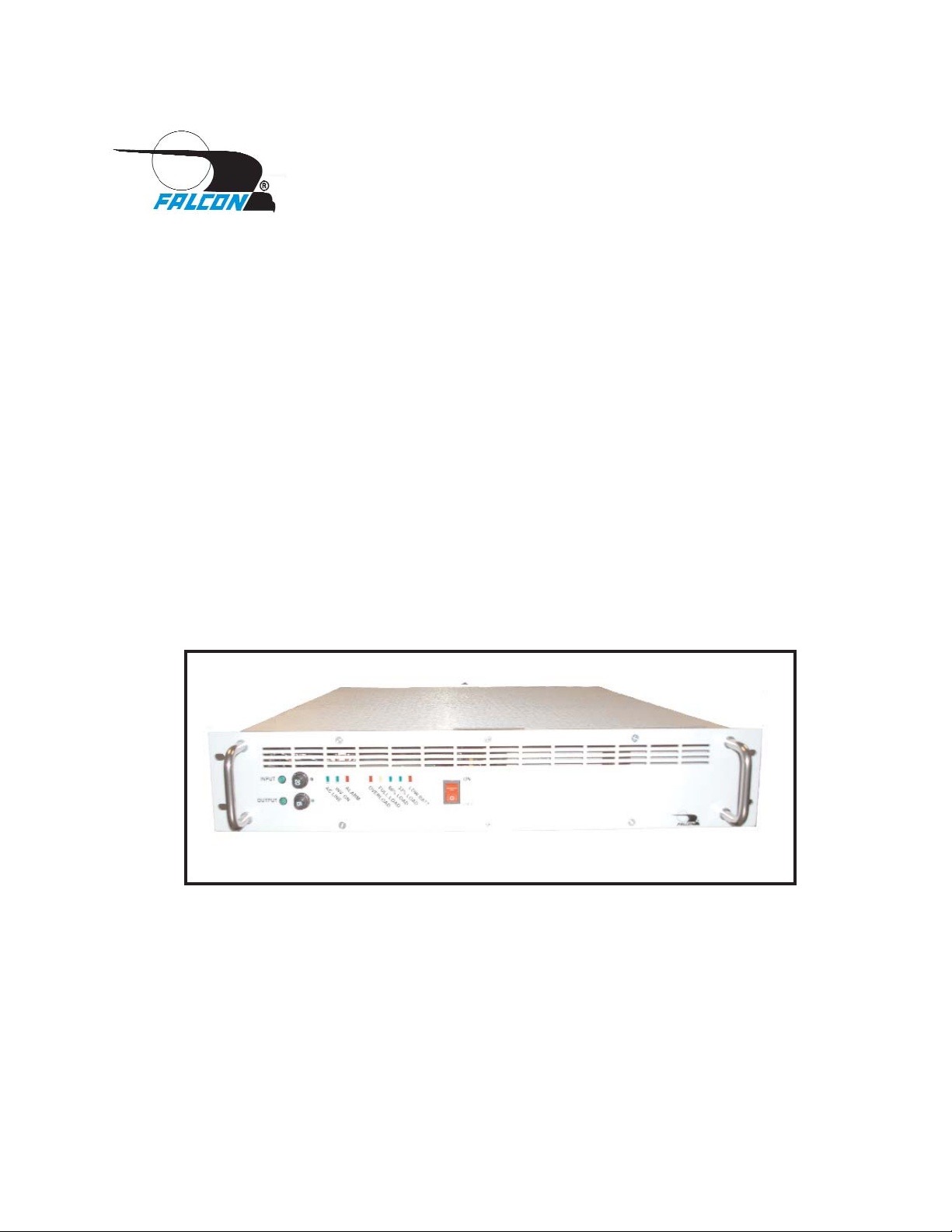
CHAPTER11
ED Series UPS - Overview
Congratulations! You have selected the highest quality protection for your
computer today. The FALCON
®
ED Series UPS offers a quiet and compact
package with superior performance you can depend on. You now own a
member of the ED family which is a proud part of the very reliable and versatile
FALCON® ED Series of UPS.
This User’s Guide is provided with your new ED unit. It will enhance your
understanding of the product and its functions. Read this handbook carefully in
the order it is presented prior to operating your unit. This will save you time and
effort in your installation and application. The illustrations will also familiarize
you with the ED's operating modes and indications. Always operate the unit
within the guidelines and specifications given to maximize the unit's efficiency
and lifetime. Also, your understanding of the product is essential in providing
you years of service for your back-up power requirements.
Refer to the cross-reference table below to understand which unit with it's power
capability corresponds to your particular model number.
MODEL NUMBER
OUTPUT POWER (VA)
ED1000RM-1
1000 (700 Watts)
ED2000RM-1
2000 (1400 Watts)
ED2400RM-1
2400 (1680 Watts)
ED2500RM-1
2500 (1750 Watts)
CROSS REFERENCE TABLE
The FALCON®ED Series represents one of the smallest and most compact
units of the FALCON®UNINTERRUPTIBLE POWER SYSTEM (UPS) product
line. In the tradition of all FALCON
®
products, it maintains the highest reliability
and the most complete on-line, sinewave power protection available. An online, sinewave UPS is the only total solution to virtually any power problem. It
effectively provides just what it says, UNINTERRUPTIBLE POWER. There is
no break, transient or glitch in source transfer during a power failure because
THERE IS NO TRANSFER.
The FALCON
®
ED SERIES is engineered with the latest MOSFET/PWM
technology for high efficiency and reliability.
2
Page 5
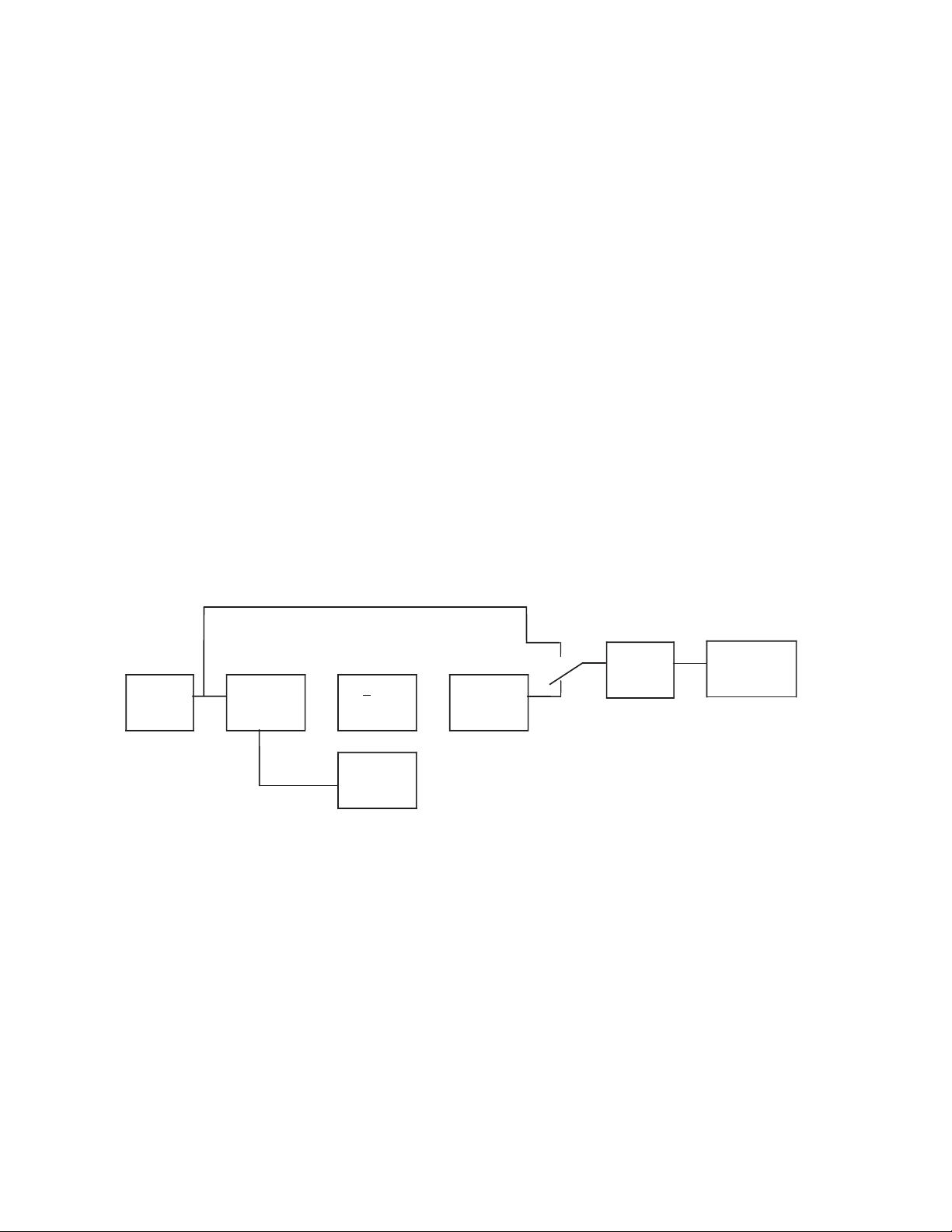
Refer to the simplified block diagram, Figure 1, for a system description. The
AC source is rectified and provides energy for the DC + Choppers and a float
charge to a standby Battery. These DC Choppers then supply the power to
operate the DC/AC Inverter.
During a utility power-loss, the AC rectification and battery charging capabilities
of the UPS become inactive. The fully-charged battery, however, supplies the
necessary power requirement to maintain the remaining system blocks.
The FALCON
®
ED on-line topology is unique to other on-line systems, in that, it
is designed to meet the needs of non-linear loads. Your computer, with its
switching power supply, is considered a non-linear load which can be very
abusive to most power protection equipment and could decrease its lifeexpectancy. The FALCON
®
ED unit is specially devised to accept these loads
and protect them efficiently without any of the output waveform degradation
common to other UPS.
Referring again to the figure below, you will notice a built-in safeguard. If the
unit inadvertently experiences an extreme over temperature situation that
causes inverter malfunction, it will switch over to a filtered emergency bypass
line to insure continuous power to the computer load. If the unit is overloaded, it
will shutdown completely if the overload is not corrected within 15 seconds.
INPUT
FILTER
RECTIFIER
CHARGER
+ DC
CHOPPERS
DC/AC
INVERTER
OUTPUT
FILTER
COMPUTER
(LOAD)
STANDBY
BATTERY
EMERGENCY
BYPASS LINE
EMERGENCY
BYPASS
SWITCH
FIGURE 1: FALCON ED SERIES BLOCK DIAGRAM
3
Page 6

UNIT NAME
E D 1000R M -1
E D 2000R M -1
E D 2400R M -1
E D 2500R M -1
Nom inal VA
1000
2000
2400
2500
Current-Input
10.4A
19A
24A
25A
Current-Output
RMS
N on-Linear (Repetitive Peak)
8.3A
20A
16.7A
38A
20.0A
45.6A
20.9A
47.6A
Input Line Plug
L5-15p
L5-30P
Output Distribution C onnectors3
(4) 5-15R
Height in(cm )
3.5 (8.9)
Width in(cm ) Front P anel
C hassis
19.0 (8.3)
17.18 (43.64
D epth in(cm )
20.25 (51.5)
Weight lbs(kg)
50 (22.7)
56 (25.4)
Std. Back-Up4 (min)
100% Load/50% Load
8/20
5/14
4/9
4/9
MODEL SELECTION GUIDE
4
Page 7

CHAPTER
CHAPTER22
Inst
allation
Inspecting the Equipment
If any FALCON®equipment has been damaged during shipment, keep
the shipping cartons and packing materials for the carrier and file a
claim for shipping damage. If you discover damage after acceptance,
file a claim for concealed damage.
To file a claim for shipping damage or concealed damage: 1) File with
the carrier within 15 days of receipt of the equipment; 2) Send a copy
of the damage claim within 15 days to the Falcon
®
Service Department.
UPS Setup
1. Verify that the following is included in the UPS shipping carton:
UPS, Owner's Guide..
2. Verify that the UPS unit is configured for the proper input/output
voltage. This information is stated on the nameplate label located on
the rear panel of the unit.
3. Select a suitable location for the UPS, near enough to the computer or
equipment to allow connection of the equipment power plug to the
receptacles located on the rear panel of the UPS.
4. When installing this UPS into a rack enclosure the following must be
followed:
a. Due to the UPS weight it must be installed using a rack
mounted shelf or using slides manufactured by General
Devices, part number CLB-203-20, using (8) Phillips, pan
head 8-32 x 3/8” screws, (4) per slide.
b. Secure the UPS front panel to the rack rails using four screws
supplied by the rack manufacturer.
5. DO NOT BLOCK UPS AIR VENTS. THE UPS MUST NOT BE
INSTALLED IN AN ENCLOSED AREA.
6. If you have not already done so, connect the equipment to be
protected to the UPS output receptacles located on the rear panel.
Verify that the connected equipment does not exceed the rated output
(in watts) of the UPS.
IMPORTANT
7. Plug the UPS power cord into the nearest grounded wall outlet. If the
UPS does not power up automatically, depress and hold the control
button located on the UPS front panel until the UPS turns on.
5
Page 8

CHAPTER
CHAPTER33
Controls, Displays & Functions
1. INPUT POWER CIRCUIT BREAKER & INDICATOR
Pull button to remove input power. The UPS will go into battery mode
when pulled.
Push the button in to reset the circuit breaker.
2. UPS OUTPUT CIRCUIT BREAKER & INFDICAT
OR
This circuit breaker provides overload protection for the UPS. Pull the
button to turn off the UPS output. Push the button to reset the circuit
breaker.
3. AC-
AC LINE INDICATOR
This green LED turns on when the utility AC is present.
4. INV- INVERTER OPERATING
The LED turns green when the UPS inverter is turned on. This LED
normally turns on a few seconds after the AC line indicator LED and
remains on during both utility and battery operation.
5. ALM-
ALARM STATUS INDICATOR
This red LED turns on and a continuous audible alarm is sounded when
the UPS is overloaded or has failed. Should this occur, check the load
level and correct any overload condition if present. During this condition,
UPS load outlets will be powered by filtered utility bypass power.Should
the unit not be overloaded, call FALCON
®
support for further assistance..
6. LOW BATT.- LOW BATTERY WARNING INDICATOR
The red LED will turn on when the UPS is operating in battery mode
and the low battery level warning point has be reached. Typically one
minute of battery runtime remains after the LED turns on.
7. OVERLOAD/ FULL LOAD/ 75% LOAD/ 50% LOAD-
Adjacent to the red low battery LED is the green 50% load LED.
Adjacent to the green 50% load LED is the green 75% load LED.
Adjacent to the green 75% load LED is the yellow 100% load LED.
Adjacent to the yellow 100% LED is the red overload LED. All overload
conditions must be corrected immediately.
8. UPS ON/OFF SWITCH
WARNING! Ths switch turns the UPS on and off. Turning this switch
to the off position will trun off power to the connected load.
1
2
3
4
5
7
6
8
6
NOTE: Reference page 10 for more details
Page 9

TYPICAL UPS REAR PANEL LAYOUT
9. DB-9F CONTACT CLOSURE INTERFACE
This connector gives access to the UPS contact closure status interface.
Please reference page 8 of this manual for details.
10. Inlet for Input Line Cord on ED1000-1 only. Line cord permenently
attached to ED1500-1 and ED2000-1.
11. COOLING
FANS (2)
Cooling fans draw cool air from the outside of the rear panel and
exhaust it out through slots in the UPS front panel. ALWAYS KEEP
COOLING FAN AND FRONT PANEL VENTS CLEAR OF DEBRIS. DO
NOT OPERATE THE UPS IN AN ENCLOSED SPACE.
12. TEST JUMPER
For test purposes only, donot remove
7
Page 10

CHAPTER
CHAPTER44
DB-9 COMMUNICATIONS INTERFACE
8
Page 11

CHAPTER
CHAPTER55
OPERATION
The FALCON®ED unit is very simple to use.
1. Verify the power cord is plugged into the correct voltage power
source.
2. Activate the power switch to the "ON" position.
3. The green AC LED illuminates.
4. The green INV LED illuminates.
5. Leave the power switch "ON" and open the input circuit breaker,.
This will simulate a power loss & test battery operation.
6. The green AC LED will shut off.
7. An intermittent audible alarm will sound.
The system will continue to operate. If this were to continue long
enough, the red LOW BATTERY light would illuminate, indicating that
battery back-up time is ending and system shutdown is imminent. The
intermittent alarm will become continuous at this point. The ED unit will
automatically shut itself off to avoid excessive battery discharge. When
power returns, normal operation of the UPS resumes without any
operator adjustment.
The duration of actual battery back-up time and the low battery condition
varies depending on the amount of load, charge on the battery, and
condition of the battery. See SPECIFICATIONS Section for approximate
hold-up times at 100% and 50% loads.
8. Reset the input circuit breaker and turn the power switch "OFF".
9. Turn off the devices you wish to plug into the UPS. Plug them into
the outlets located on the rear of the UPS.
10. Activate the ED unit power switch to the "ON" position.
11. Turn "ON" each of your devices.
12. Some of the LOAD indicators may illuminate. The amount of load
determines the actual number of indicators lit.
The bottom green L.E.D. signifies approximately 50% of load
capacity. The second green L.E.D. represents approximately 75%
of load capacity. If the yellow L.E.D. illuminates, full load has been
achieved. If the red light illuminates, an OVERLOAD condition is
present. If this situation continues for about 15 seconds, the unit
will automatically shut off.
If the system overheats or the Inverter should fail, the unit
automatically transfers the load to a filtered bypass line, sounds a
continuous alarm and the red ALM light will illuminate.
9
Page 12

To escape this condition, the problem must first be corrected then
turn the UPS power switch "OFF", then back "ON".
It is recommended that you leave the ED unit power switch "ON"
at all times and switch your devices "OFF" individually. This will
insure that your batteries are always at a maximum charged state.
The power switch acts as a system ON/OFF switch. When this switch is
turned "OFF", power is lost to the entire unit including all outlets at the
rear of the UPS, since the battery circuit is also disabled.
WARNING
10
Page 13

CHAPTER
CHAPTER66
Maintenance & Technical Support
1. Care & Maintenance
Falcon®ED Series UPSs are designed to be maintenance-free.
They can be cleaned with a damp cloth or non-abrasive cleanser, providing the
UPS is turned off and the input plug is disconnected from the utility source.
On a regular basis, check the vents to make sure they are kept free from
accumulation of dust, dirt or lint.
2. Battery Life vs. Temperature
For full battery life, keep the UPS close to an ambient temperature of 77ºF.
The batteries should never be exposed to temperatures below 40ºF and above
104ºF
.
3. Battery Replacement
This UPS contains sealed maintenance-free batteries (VRLA). When situated in
a typical office environment, with the proper charging and limited cycling, these
batteries can last many years. We recommend that the batteries be replaced
every three years.
Never attempt to service batteries. High voltage exists within the unit, which
could cause electrical shock. Servicing of batteries should be performed or
supervised by personnel knowledgeable of batteries and the required
precautions. Keep unauthorized personnel away from batteries.
When replacing the UPS batteries, use the same number and type of batteries.
A. NEVER dispose of batteries in a fire, as batteries will explode.
B. NEVER dispose of used batteries or the UPS in the trash or landfill as it is
against federal and state laws. The UPS and Batteries must be recycled.
For UPS and battery recycling information, please contact our service
department for the name and address of the nearest battery recycling facility.
C. Spent batteries must be recycled in accordance with all Federal, State
and local laws. To locate a recyaling center near you contact the Falcon
service department.
A. Do not open or mutilate the battery or batteries. Released electrolyte is
harmful to the skin and eyes. It may be toxic.
B. Abattery can present a risk of electrical shock and high short circuit current.
REFER ALL BATTERY SERVICING OR REPLACEMENT TO A QUALIFIED
SERVICE TECHNICIAN. UNTRAINED PERSONNEL SHOULD NEVER
ATTEMPT BATTERY REPLACEMENT.
WARNING
NEVER
CAUTION
11
Page 14

The following precautions should be observed by a qualified technician when
working with batteries.
1. Remove watches, rings, or other metal objects.
2. Use tools with insulated handles.
3. Wear rubber gloves and boots.
4. Do not lay tools or metal parts on top of batteries
4. Storing the UPS and Batteries
Should you need to store the UPS for a long period, fully recharge the battery
just prior to storage and recharge the battery every 6 months by plugging the
UPS into a power outlet and turning the UPS on. It is recommended that the
batteries charge for 24 hours after long-term storage.
5. FCC
This equipment generates and uses radio frequency energy and if not installed
and used properly in strict accordance with the manufacturer's instructions,
may cause interference to radio and television reception. All models covered in
this manual have been tested and found to comply with the limits for a Class A
computing device, in accordance with the specifications in FCC regulations,
Part 15, Subpart J, which are designed to provide reasonable protection
against such interference.
If this equipment does cause harmful interference to radio or television
reception, which can be determined by turning the equipment off and on, the
user is encouraged to try to correct the interference by one or more of the
following measures:
a. Reorient or relocate the receiving antenna.
b. Increase the separation between the equipment and the receiver.
c. Connect the equipment into an outlet on a circuit different from that to
which the receiver is connected.
d. Consult the dealer or an experienced radio/television technician for
assistance.
12
Page 15

6. Technical Support
Your FALCON®Electric ED Series UPS is backed by one of the finest customer
service teams assembled. Write, Call, Fax or Email should you require
technical assistance or service.
FALCON ELECTRIC, INC.
Irwindale, CA. 91706
Voice 626.962.7770
Fax 626.962.7720
Service 800.842.6940
Email: service@falconups.com
WWW.FALCONUPS.COM
Should service be desired, you must first obtain a Return Material Authorization
number (RMA) and return shipping instructions from our customer service
department. Please have your UPS model, serial numbers and date of
purchase on hand prior to the call. This information is located on the
identification label on the rear panel of the unit. This information is essential in
retrieving your unit's historical records.
The RMA number issued must appear on the outside of the shipping carton.
The original shipping container must be used when returning any ED
Series product. Falcon
®
Electric will not assume any responsibility for shipping
damage. In the event of shipping damage you will be charged for repairs due
to the damage.
All units must be returned prepaid. The address and shipping instructions will
be given to you at the time the RMA is issued.
7. Requesting Technical Information or Support.
You may request technical information or support by Email or telephone.
Please send your technical or support questions by Email to:
SUPPORT@FALCONUPS.COM
You may contact a FALCON support engineer directly by calling the FALCON
support line between 9:00 am and 4:00 pm PST.
626.962.7770
8. FALCON Web Support
Product data sheets, specification and owner’s guides are available in Adobe
.PDF format on our corporate website.
WWW.FALCONUPS.COM
13
5116 Azusa Canyon Road
 Loading...