

Falcon E9541, E9541R, E9541CR, E9581, E9581CR User, Installation And Servicing Instructions
...Page 1
F900 SERIES
User, installation and servicing instructions
COUNTERTOP
GRIDDLES
E9541, E9541CR, E9541R, E9581, E9581CR, E9581R
Read these instructions before use
T100948
Published: 12/05/17
DATE PURCHASED:
MODEL NUMBER:
SERIAL NUMBER:
DEALER:
SERVICE PROVIDER:
REV 4
Page 2

2
Falcon Foodservice Equipment
HEAD OFFICE
Wallace View, Hillfoots Road, Stirling. FK9 5PY. Scotland.
WEEE Directive Registration No. WEE/DC0059TT/PRO
At end of appliance life, dispose of appliance and any replacement parts in a safe
manner, via a licensed waste handler. Appliances are designed to be dismantled
easily and recycling of all material is encouraged whenever practicable.
Dear Customer,
Thank you for choosing Falcon Foodservice Equipment.
This manual can be downloaded from www.falconfoodservice.com or scan
here.
IMPORTANT: Please keep this manual for future reference.
Page 3
3
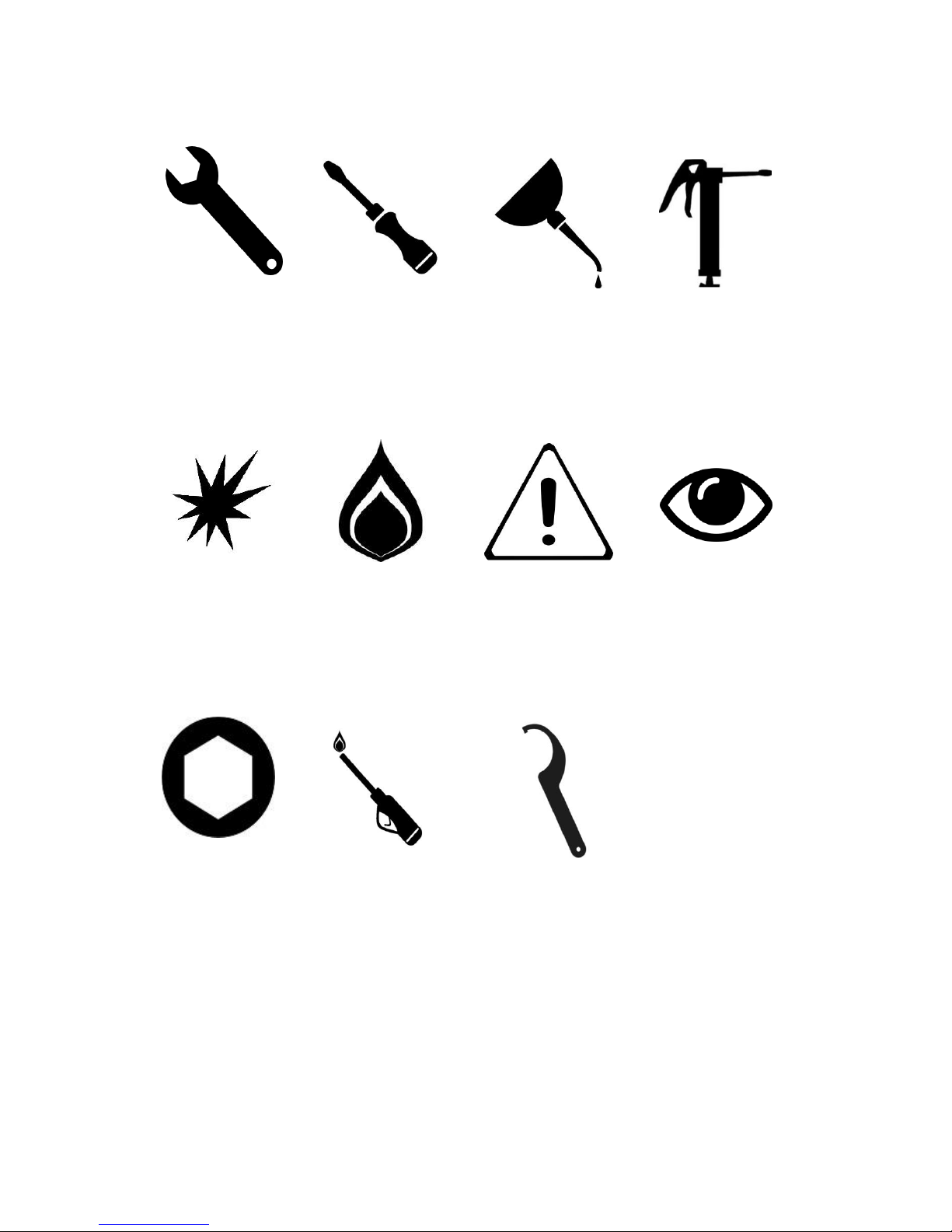
SYMBOLS.
• SPANNER • SCREWDRIVER • COOKING OIL • GREASE
• SPARK IGNITION • FLAME • WARNING • VIEWPORT
• ALLEN KEY •IGNITER •C SPANNER
Page 4

4
These instructions are only valid if the country code appears on the
appliance. If the code does not appear on the appliance, refer to the
technical instructions for adapting the appliance to the conditions for use
in that country.
Installation must meet national or local regulations. Attention must be paid
to: safety (installation & use) regulations, health and safety at work act,
local and national building regulations, fire precautions act.
To prevent shocks, all appliances must be earthed.
This appliance has been CE-marked on the basis of compliance with the
Low Voltage and EMC Directives for the voltages stated on the data plate
This equipment is for professional use only and must be used by qualified
persons.
The installer must instruct the responsible person(s) of the correct
operation and maintenance of the appliance.
Only competent persons are allowed to service this appliance.
Unless otherwise stated, parts which have been protected by the
manufacturer must not be adjusted by the installer.
Take care when moving an appliance fitted with castors.
The appliance must be serviced regularly by a qualified person. Service
intervals should be agreed with the service provider.
Check that no damage has occurred to the appliance, power cable, or plug
during transit. If damage has occurred, do not use this appliance.
Installation, periodic testing, repair and fixed wiring connections should
only be undertaken by a competent electrician.
Ensure power cable is routed free from the appliance to avoid damage.
We recommend supplementary electrical protection with the use of a
residual current device (RCD)
The appliance has been designed and approved to use Falcon Kick plates,
non Falcon kick plates could potentially adversely affect the performance
of the appliance by restricting the air to the appliance.
Page 5

5
CONTENTS
1.0 APPLIANCE INFORMATION ................................................................................................. 6
2.0 OPERATION ............................................................................................................................. 7
2.1 COMPONENT PARTS ............................................................................................................... 7
2.2 USING THE GRIDDLE ................................................................................................................ 7
3.0 CLEANING AND MAINTENANCE ........................................................................................ 7
4.0 SPECIFICATION ...................................................................................................................... 8
5.0 DIMENSIONS / CONNECTION LOCATIONS ..................................................................... 9
6.0 INSTALLATION ........................................................................................................................... 10
6.1 SITING / CLEARANCES ................................................................................................................. 10
6.2 ASSEMBLY ................................................................................................................................... 10
6.3 COMMISSIONING ........................................................................................................................ 12
6.4 SUITING ................................................................................................................................. 13
7.0 SERVICING .................................................................................................................................. 15
7.1 CONTROL PANEL REMOVAL ........................................................................................................ 15
7.2 ELEMENT TRAY REMOVAL .......................................................................................................... 16
7.3 OPERATING THERMOSTAT REMOVAL......................................................................................... 17
7.4 ELEMENT REMOVAL .................................................................................................................... 18
7.5 SAFETY THERMOSTAT REMOVAL (CHROME GRIDDLE ONLY) ..................................................... 18
7.6 SAFETY THERMOSTAT RESET (CHROME GRIDDLE ONLY) ............................................................ 19
7.7 CIRCUIT DIAGRAMS ..................................................................................................................... 20
7.8 WIRING DIAGRAMS ..................................................................................................................... 24
8.0 FAULT FINDING .......................................................................................................................... 28
9.0 SPARE PARTS ............................................................................................................................ 28
10.0 SERVICE INFORMATION ....................................................................................................... 29
Page 6
6
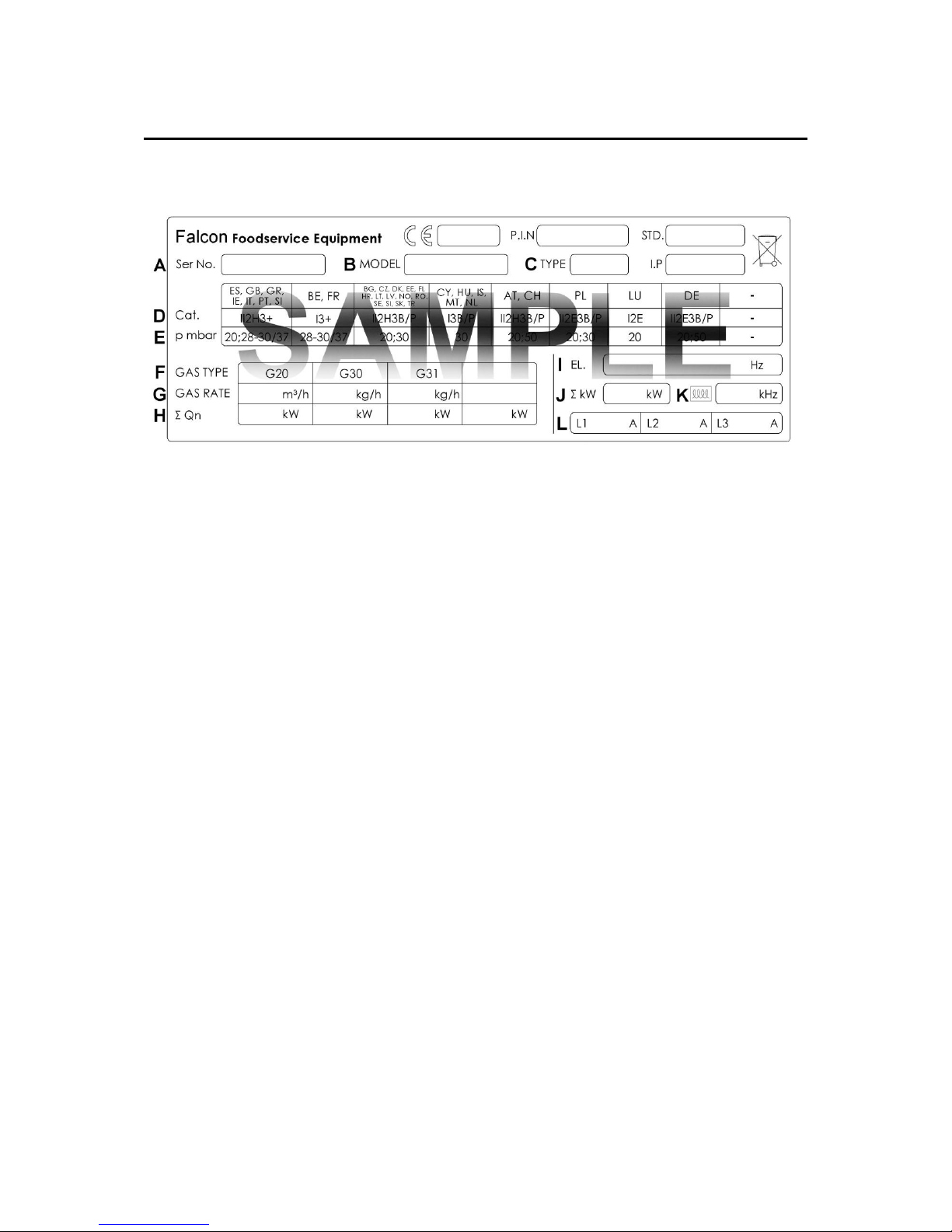
1.0 APPLIANCE INFORMATION
This appliance has been CE-marked on the basis of compliance with the relevant EU
directives for the heat inputs, gas pressures and voltages stated on the data plate.
A - Serial No
B - Model No
C - Flue Type
D - Gas Category
E - Gas Pressure
F - Gas Type
G - Gas Rate
H - Total Heat Input
I - Electrical Rating
J - Total Electrical Power
K - Magnetic Field Frequency
L - Electrical Phase Loading
Page 7

7
2.0 OPERATION
2.1 COMPONENT PARTS
A – Griddle plate
B – Power neon (red)
C – Heat demand
neon (amber)
D – Thermostat
control knob
E – Fat jug
2.2 USING THE GRIDDLE
2.2.1 Before use, clean the appliance. See section 3.
2.2.2 Set temperature control to desired setting.
2.2.3 To switch the unit off, turn temperature control to `off` position.
3.0 CLEANING AND MAINTENANCE
3.1 Turn off and cool down.
3.2 Scrape off burnt on food.
3.3 Remove other debris using a cloth.
3.4 Clean fat jug.
3.5 The flue capper can be removed for cleaning, but must be replaced before use.
DO NOT USE METAL UTENSILS ON CHROME GRIDDLE.
FAILURE DUE TO LACK OF PROPER CLEANING IS NOT
COVERED BY WARRANTY.
Page 8
8
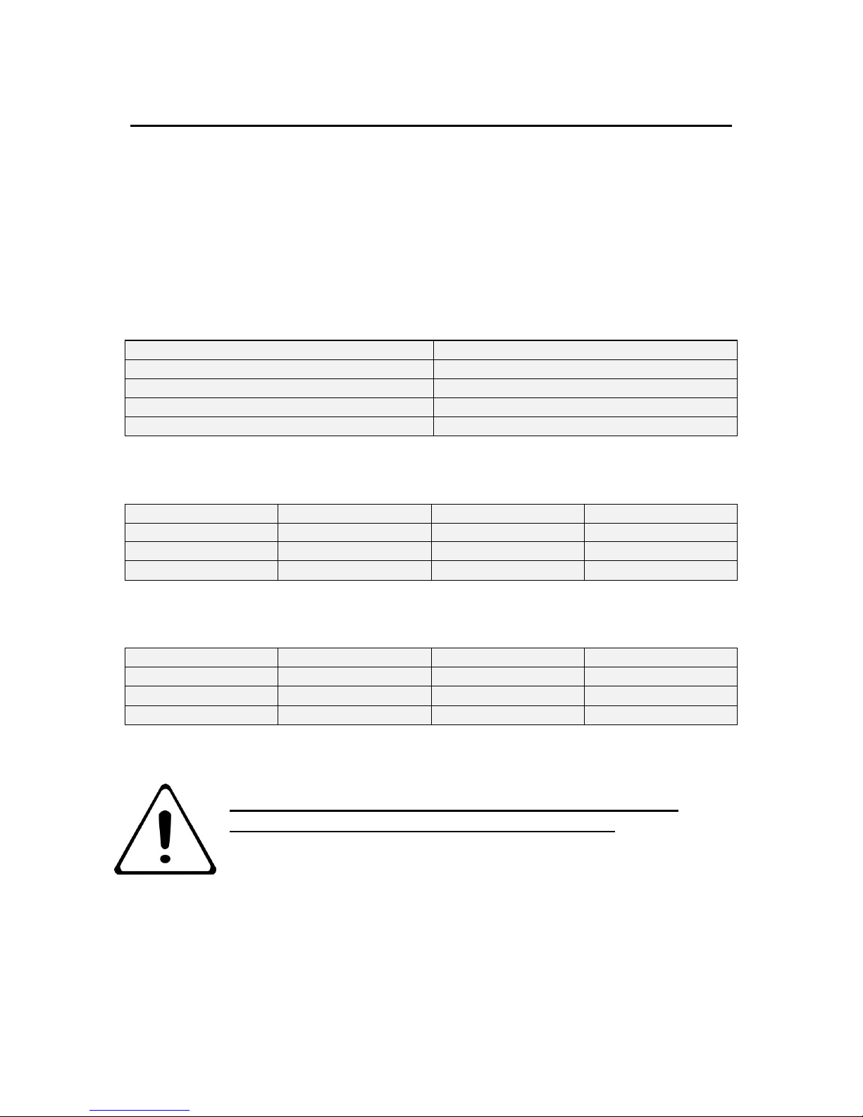
4.0 SPECIFICATION
4.1 This unit is suitable for AC supplies only
4.2 The standard terminal arrangement is Three phase (400V 3N~) for all variants.
4.3 To convert the appliance from three phase to single phase supply, insert links
between phases 1, 2 and 3. Consideration must be given to required draw of current.
THIS APPLIANCE MUST BE EARTHED.
Live 1 ( Phase 1)
Brown
Live 2 ( Phase 2)
Black
Live 3 ( Phase 3)
Grey
Neutral
Blue
Earth
Yellow/Green
E9541, E9541CR, E9541R
Phase
Min
Max
Actual (A)
L1
8.6
10.03
9.56
L2
8.6
10.03
9.56
L3
E9581, E9581CR, E9581R
Phase
Min
Max
Actual (A)
L1
8.6
10.03
9.56
L2
17.2
20.07
19.12
L3
8.6
10.03
9.56
IF ANY CURRENT IS OUT WITH THESE TOLERANCES, THE
CAUSE MUST BE INVESTIGATED AND RECTIFIED.
Page 9
9
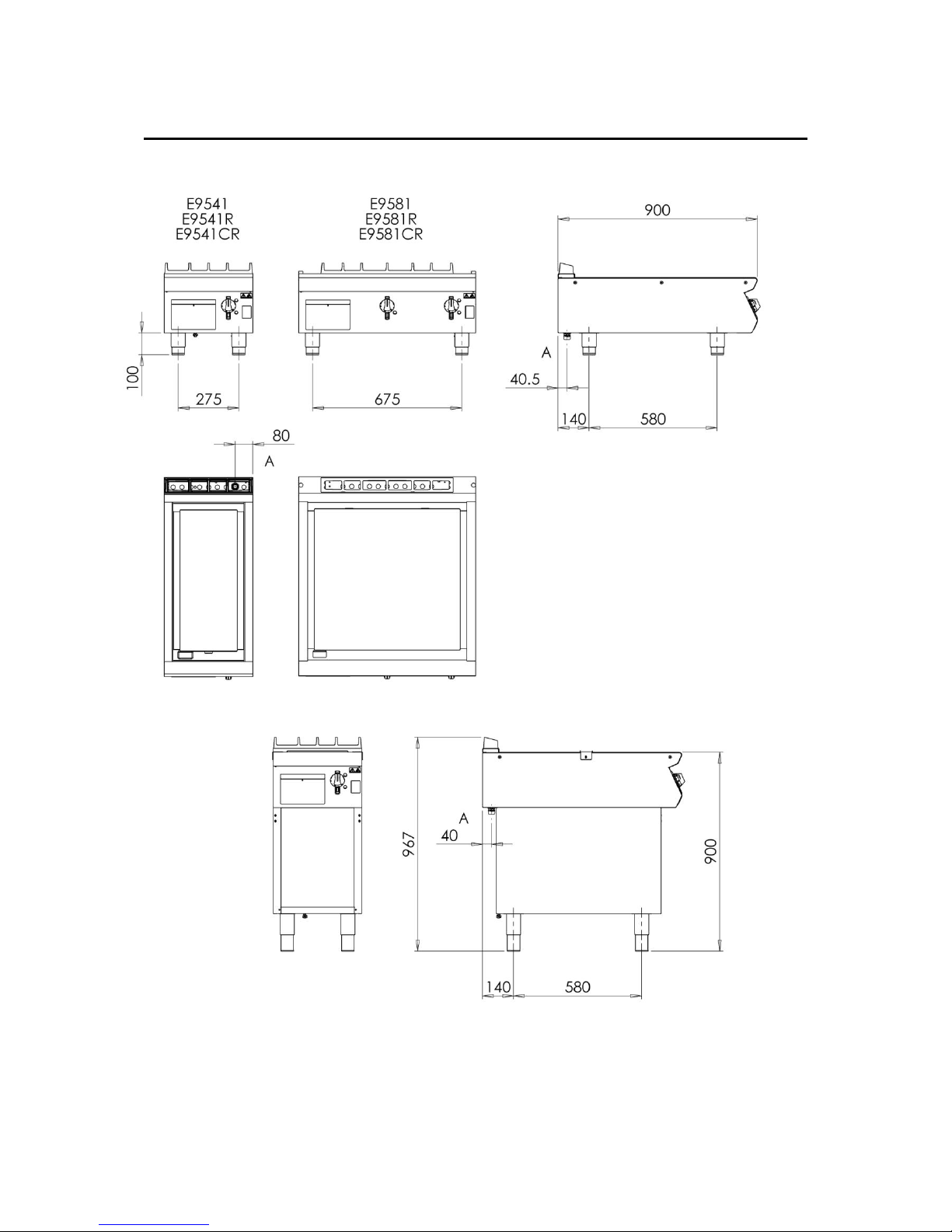
5.0 DIMENSIONS / CONNECTION LOCATIONS
Page 10

10
6.0 INSTALLATION
6.1 SITING / CLEARANCES
Where this appliance is to be positioned in close proximity to a wall,
partitions, kitchen furniture, decorative finishes, etc., it is recommended
that they be made of non-combustible material; if not, they shall be clad
with a suitable non-combustible heat insulating material, and that the
closest attention be paid to fire prevention regulations. If suiting, the
necessary clearances to any combustible wall must be the largest figure
given for individual appliance instructions.
6.2 ASSEMBLY
6.2.1 Position appliance and level using feet adjusters as shown below.400 wide models
on stands should be fitted with the anti tilt device.
Page 11

11
6.2.2 Connect appliance to mains supply
Page 12

12
6.3 COMMISSIONING
6.3.1 Remove rear access plate and control panel.
6.3.2 Push the power cable through the gland and feed to the mains connector block.
6.3.3 Attach appropriate 3 phase mains power cable with 32A plug.
6.3.4 Refit rear access panel and control panel.
6.3.5 Connect appliance to mains power.
6.3.6 Ensure red neon illuminates.
6.3.7 Turn thermostat(s) to desired temperature.
6.3.8 Ensure amber neon(s) illuminates.
6.3.9 This appliance is also provided with a terminal for connection of an external
equipotential conductor. This terminal is an effective electrical contact with all fixed
exposed metal parts of the appliance, and shall allow the connection of conductor
having a nominal cross-section area of up to 10mm².
it is located at the rear of the unit and identified by the following label and must only
be used for bonding purposes.
PLEASE FILL OUT THE INFORMATION TABLE ON THE FRONT COVER
AFTER COMMISSIONING.
Page 13

13
6.4 SUITING
“Patent pending, application no. GB 1511389.7”
6.4.1 Before leveling and suiting units ensure the units are fully built, including all
accessories and castings.
6.4.2 Undo the 4 fixing screws on the control panel and remove.
6.4.3 Remove the hob rear infill and replace with rear suiting plate and fixings.
6.4.4 Remove the front side panel countersunk screw and suiting plate.
NOTE: The DLS system is designed to give a quick and easy suiting solution. If
you require an improved seal between appliances we recommend you
use, a food grade, high temperature silicon sealant. This can be
supplied by Falcon part no – 523400021
6.4.5 If required, run a bead of silicon 5mm from profile edge as highlighted below.
Page 14

14
6.4.6 Slide suited units into position.
6.4.7 (A) Right hand unit: Screw the M5 x 40 screw (supplied in the kit) into one of the
suiting plates as shown and then insert through the front fixing holes of both units.
6.4.8 (B) Left hand unit: Slide the penny and lock washer on to the screw and secure using
the M5 nut.
6.4.9 (C) Remove the front bolts from feet, insert base tie plate and secure the bolts back
into position.
6.4.10 (D) Replace fixings on the rear hob and tighten screw caps into position.
6.4.11 Replace control panel
A
C D B
Page 15

15
7.0 SERVICING
BEFORE ATTEMPTING ANY MAINTENANCE, ISOLATE THE
APPLIANCE AT THE MAINS SWITCH AND TAKE STEPS TO ENSURE
THAT IT IS NOT INADVERTENTLY SWITCHED ON.
THE GRIDDLE PLATES ON THE E9500 SERIES ELECTRIC GRIDDLES
ARE FIXED TO THE HOB PANEL AND ALL SERVICING SHOULD BE CARRIED OUT
WITHOUT THE REMOVAL OF THE PLATE.
ALL ILLUSTRATIONS ARE BASED ON THE 800mm MODELS
7.1 CONTROL PANEL REMOVAL
7.1.1 Remove panel as shown.
Page 16

16
7.2 ELEMENT TRAY REMOVAL
7.2.1 Remove control panel as shown in 7.1
7.2.2 Remove wiring from element tails.
7.2.3 Loosen the 2 front M5 nuts holding the element tray.
7.2.4 Lift up element tray and slide rearwards.
7.2.5 Lower tray free of mounting brackets ensuring thermostat capillaries clear their slots
in tray.
7.2.6 Remove tray through front of appliance ensuring insulation does not snag on element
tails.
Page 17

17
7.3 OPERATING THERMOSTAT REMOVAL
7.3.1 Remove control panel as shown in 7.1
7.3.2 Remove control knob.
7.3.3 Remove thermostat mounting screws.
7.3.4 Remove element tray as shown in 7.2
7.3.5 Loosen nuts on phial clamps.
7.3.6 Carefully pull phial forward free of the clamp.
7.3.7 When replacing the phial ensure you re-fit the vidaflex sleeve to the capillary and the
phial is pushed fully in until it hits the end of the phial clamp before fully tightening the
clamp nuts.
Page 18

18
7.4 ELEMENT REMOVAL
7.4.1 Remove control panel as shown in 7.1
7.4.2 Remove wiring from element tails.
7.4.3 Remove element tray as shown in 7.2
7.4.4 Loosen nuts on rear clamp.
7.4.5 Remove nuts and clamps from front & centre of element.
7.4.6 Slide element forward free of rear clamp.
7.5 SAFETY THERMOSTAT REMOVAL (CHROME GRIDDLE ONLY)
Page 19

19
7.5.1 Remove control panel as shown in 7.1
7.5.2 Remove safety thermostat fixing screws.
7.5.3 Remove the wires from the safety thermostat, noting the wire numbers.
7.5.4 Remove element tray as shown in 7.2
7.5.5 Loosen nuts on phial clamps.
7.5.6 Carefully pull phial forward free of the clamp.
7.5.7 When replacing the phial ensure you re-fit the vidaflex sleeve to the capillary, the
capillary is supported in the two guides and the phial is pushed fully in until it hits the
end of the phial clamp before fully tightening the clamp nuts.
7.6 SAFETY THERMOSTAT RESET (CHROME GRIDDLE ONLY)
Allow the griddle plate to cool down prior to resetting the thermostat.
7.6.1 Remove control panel as shown in 7.1
7.6.2 Push in the red reset button with your finger.
NOTE: Reset button is sensitive. Do not use excessive force.
IF THE SAFETY THERMOSTAT HAS ACTIVATED, THE REASON FOR
OVERHEATING MUST BE IDENTIFIED AND REMEDIED BEFORE
RETURNING THE UNIT TO SERVICE
Replace all parts in reverse order
Page 20

20
7.7 CIRCUIT DIAGRAMS
7.7.1 E9541 / E9541R
Page 21

21
7.7.2 E9541CR
Page 22

22
7.7.3 E9581 / E9581R
Page 23

23
7.7.4 E9581CR
Page 24

24
7.8 WIRING DIAGRAMS
7.8.1 E9541 / E9541R
Page 25

25
7.8.1 E9541CR
Page 26

26
7.8.1 E9581 / E9581R
Page 27

27
7.8.1 E9581CR
Page 28

28
8.0 FAULT FINDING
FAULT
POSSIBLE CAUSES
REMEDY
No power (red neon
extinguished)
Appliance disconnected from
mains power
Reconnect to mains power
No heat when thermostat
turned on (amber neon
extinguished)
Appliance internal fuse blown
Investigate reason, rectify
fault, replace fuse
Faulty thermostat
Replace
Safety thermostat tripped
Reset/investigate reason
No heat when thermostat
turned on (amber neon
illuminated)
Faulty contactor
Replace
Faulty element
Replace
Appliance not hot enough
Faulty thermostat
Replace.
Note: when checking plate
temperature, probe 210mm
in from each side halfway
between front and rear on
E9581 models. Probe centre
plate on E9541 models
9.0 SPARE PARTS
Mains Pilot light RED 730962010
Circuit Pilot light AMBER 730962040
Element 230V 733620006
Thermostat E9581/81R/41/41R 731910500
Thermostat E9581CR/41CR 733630002
Safety thermostat E9581CR/41CR 733630003
Control knob E9581/81R/41/41R 733620005
Control Knob E9581CR/41CR 733630004
When ordering spares, quote the following:
Model Number
Serial number
Gas Type
This information is found on data plate on front panel. (see section 1.0)
Visit our website for further spares information.
Page 29

29
10.0 SERVICE INFORMATION
It is recommended to have a maintenance contract with a local service provider.
SERVICELINE CONTACT:
(UK only)
Phone: +441438 363 000
Warranty Policy Shortlist
For our warranty policy please go to www.falconfoodservice.com
 Loading...