

Page 1
F900 SERIES
User, installation and servicing instructions
ELECTRIC CHARGRILL
E9460/E9490
T100896
Rev No 3
Published: 23/05/2019
DATE PURCHASED:
MODEL NUMBER:
SERIAL NUMBER:
DEALER:
SERVICE PROVIDER:
Read these instructions before use
1
Page 2

WEEE Directive Registration No. WEEE/DC0059TT/PRO
At end of appliance life, dispose of appliance and any replacement parts in a
safe manner, via a licensed waste handler. Appliances are designed to be
dismantled easily and recycling of all material is encouraged whenever
practicable.
Dear Customer
Thank you for choosing Falcon Foodservice Equipment.
This manual can be downloaded from www.falconfoodservice.com or scan
here:
IMPORTANT: Please keep this manual for future reference.
Falcon Foodservice Equipment
HEAD OFFICE
Wallace View, Hillfoots Road, Stirling. FK9 5PY. Scotland.
2
Page 3

SYMBOLS
SCREWDRIVER
SPANNER
COOKING OIL
GREASE
WARNING
SPARK IGNITION
FLAME
VIEWPORT
ALLEN KEY
IGNITER
C SPANNER
REMOVE DEVICE
PLUG REMOVER
3
Page 4

This appliance may be discoloured due to testing.
These instructions are only valid if the country code appears on the appliance. If
the code does not appear on the appliance, refer to the technical instructions for
adapting the appliance to the conditions for use in that country.
Installation must meet national or local regulations. Attention must be paid to:
safety (installation & use) regulations, health and safety at work act, local and
national building regulations, fire precautions act.
To prevent shocks, this appliance must be earthed.
This unit is fitted with an equipotential connection at the rear on the base.
This appliance has been CE-marked on the basis of compliance with the Low
Voltage and EMC Directives for the voltages stated on the data plate.
This equipment is for professional use only and must be used by qualified
persons.
The installer must instruct the responsible person(s) of the correct operation and
maintenance of the appliance.
Unless otherwise stated, parts which have been protected by the manufacturer
must not be adjusted by the installer.
The appliance must be serviced regularly by a qualified person. Service intervals
should be agreed with the service provider.
Check that no damage has occurred to the appliance or supply cord during transit.
If damage has occurred, do not use this appliance.
Ensure the supply cord is routed free from the appliance to avoid damage.
The appliance has been designed and approved to use Falcon kick plates; non
Falcon kick plates could potentially adversely affect the performance of the
appliance by restricting the air to the appliance.
All apparatus connected to a potable water network and including water drain
device has to be provided with an air break before its discharge to the drainage
system. Type AA.
4
Page 5

Training and competence
To help ensure the safe use of this appliance there is a requirement for you to provide
whatever information, instruction, training and supervision as is necessary to ensure, so
far as is reasonably practicable, the health and safety of all users.
For further help and information on training and competence we would refer you the
Health and Safety Executive website; www.hse.gov.uk document ref: health and safety
training INDG345. International customers should default to the health and safety
guidelines provided by your government body.
Risk assessment
As part of managing the health and safety of your business you must control any risks
identified in your commercial kitchen. To do this you need to think about what might
cause harm to people and decide whether you are taking reasonable steps to prevent
that harm. This is known as risk assessment. It is important to consider the environment
around the product as well as the product itself. For example oil or food spills will present
a significant risk so users so the need to immediately clean up such spills must be
reflected in staff training.
For further help and information on risk assessments we would refer you to you the
Health and Safety Executive website; www.hse.gov.uk document ref: risk assessment
INDG163. International customers should default to the health and safety guidelines
provided by your government body.
5
Page 6

CONTENTS
1.0 APPLIANCE INFORMATION ..................................................................................... 7
2.0 OPERATION .............................................................................................................. 8
2.1 COMPONENT PARTS ............................................................................................ 8
2.2 CONTROLS .......................................................................................................... 10
2.3 USING THE APPLIANCE ..................................................................................... 11
2.4 CHEF’S RECOMMENDATIONS ........................................................................... 11
3.0 CLEANING AND MAINTENANCE ........................................................................... 12
3.1 CLEANING AND MAINTENANCE ........................................................................ 13
3.2 PTFE FITTING ...................................................................................................... 15
4.0 SPECIFICATION ...................................................................................................... 16
4.1 APPLIANCE WEIGHT TABLE .............................................................................. 16
4.2 TECHNICAL DATA TABLE ................................................................................... 16
5.0 DIMENSIONS / CONNECTION LOCATIONS .......................................................... 17
6.0 INSTALLATION ....................................................................................................... 18
6.1 SITING / CLEARANCES ....................................................................................... 19
6.2 ASSEMBLY .......................................................................................................... 20
6.3 ELECTRIC SUPPLY & CONNECTION ................................................................. 20
6.4 COMMISSIONING ................................................................................................ 21
6.5 SUITING ............................................................................................................... 22
7.0 SERVICING ............................................................................................................. 25
7.1 ACCESS PANEL REMOVAL ................................................................................ 26
7.2 CONTROL PANEL REMOVAL ............................................................................. 26
7.3 ENERGY REGULATOR, SWITCH AND NEON REMOVAL .................................. 27
7.4 CONTACTOR REMOVAL ..................................................................................... 28
7.5 MICRO SWITCH REMOVAL ................................................................................ 28
7.6 HEATING ELEMENTS REMOVAL ....................................................................... 29
7.7 CIRCUIT DIAGRAMS ........................................................................................... 31
7.8 WIRING DIAGRAMS ............................................................................................ 33
8.0 ACCESSORIES ....................................................................................................... 35
9.0 FAULT FINDING ...................................................................................................... 35
10.0 SPARE PARTS ........................................................................................................ 36
11.0 SERVICE INFORMATION ........................................................................................ 37
6
Page 7
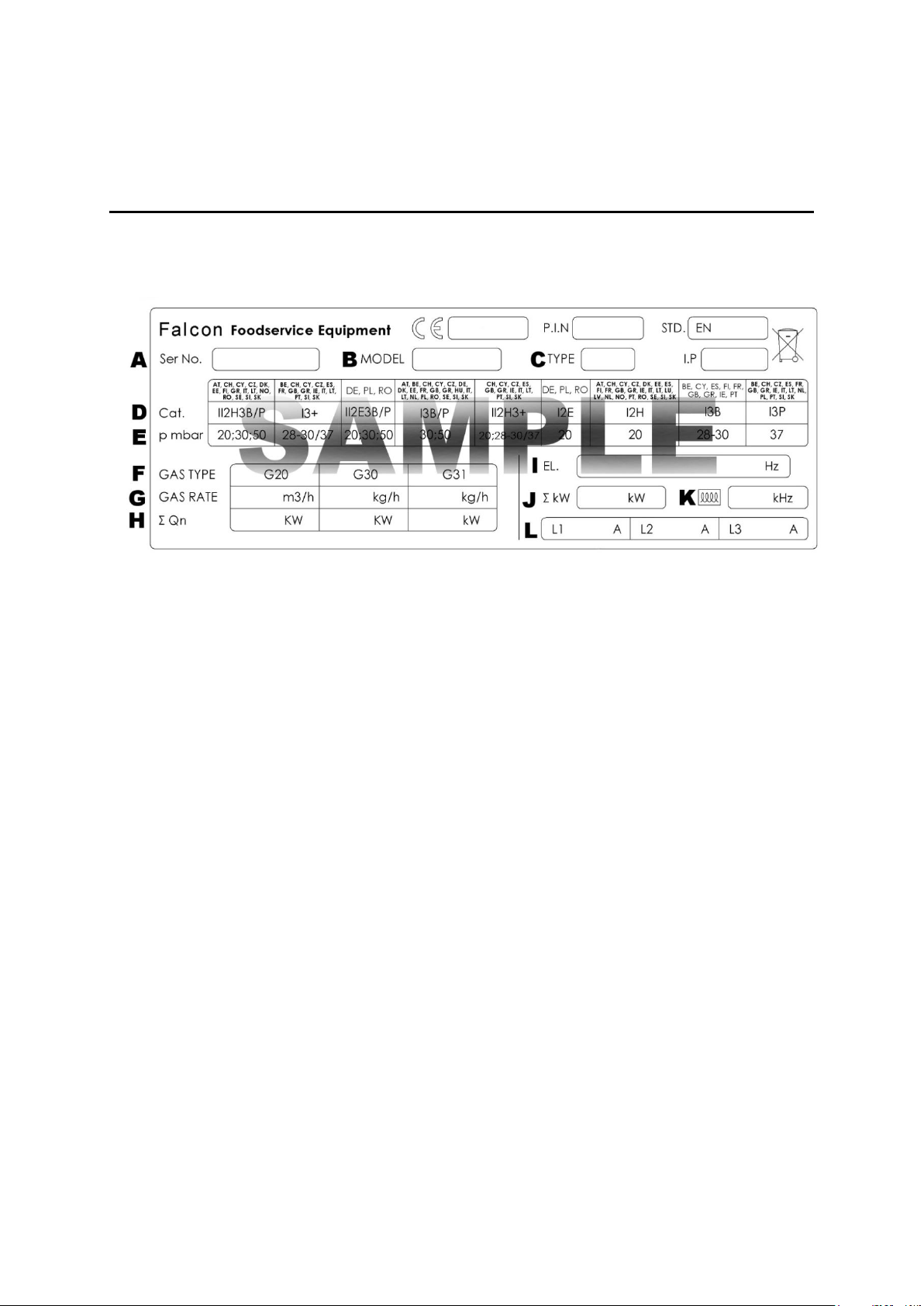
1.0 APPLIANCE INFORMATION
This appliance has been CE-marked on the basis of compliance with the relevant EU
directives for the heat inputs, gas pressures and voltages stated on the data plate.
A - Serial No
B - Model No
C - Flue Type
D - Gas Category
E - Gas Pressure
F - Gas Type
G - Gas Rate
H - Total Heat Input
I - Electrical Rating
J - Total Electrical Power
K - Magnetic Field Frequency
L - Electrical Phase Loading
7
Page 8
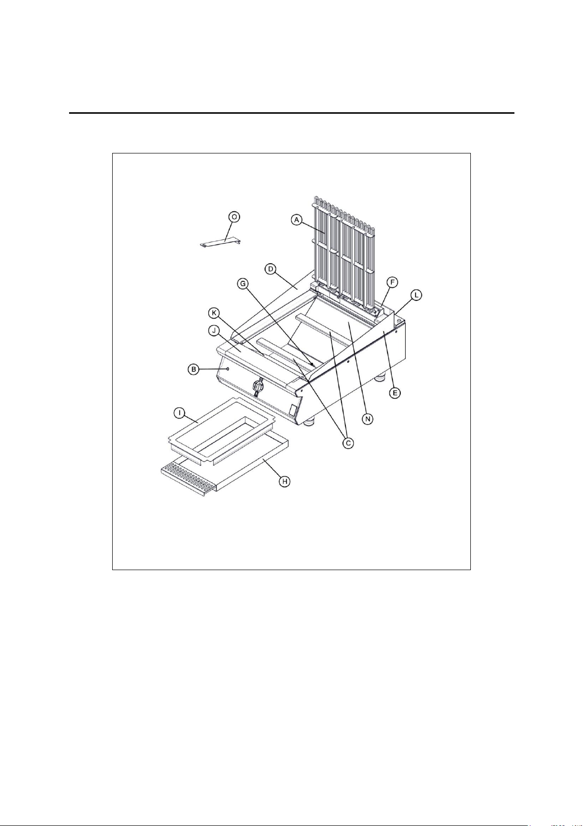
E9460
A -
Element
H -
Drip Tray
B -
Power neon (Red)
I -
Drip Tray Insert
C -
Element supports
J-
PTFE Front Clamp
D -
Left hand splashguard
K-
PTFE Front Liner
E -
Right hand splashguard
L-
PTFE Rear Clamp
F-
Rear splashguard infill
N-
PTFE Rear Liner
G-
Drain
O-
Cleaning tool
2.0 OPERATION
2.1 COMPONENT PARTS
8
Page 9
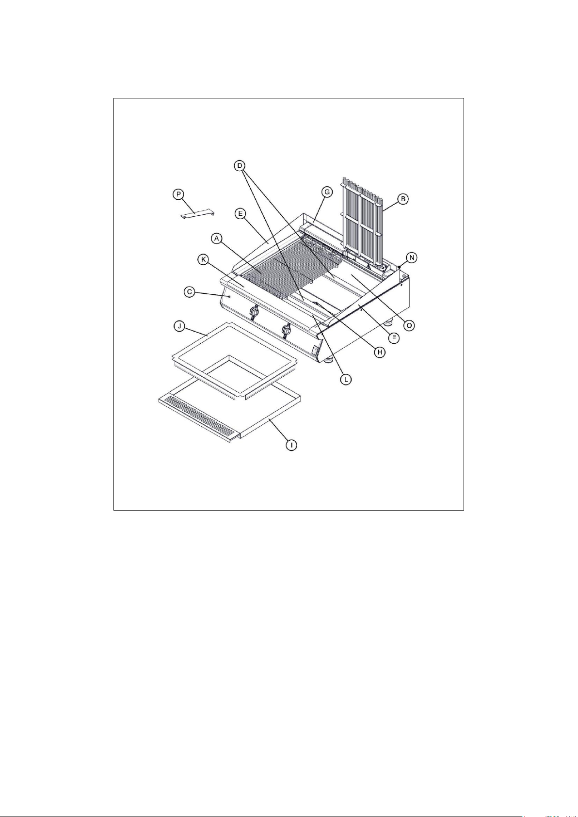
E9490
A -
LH Element
I-
Drip tray
B -
RH Element
J-
Drip Tray Insert
C -
Power neon (Red)
K-
PTFE Front Clamp
D -
Element supports
L-
PTFE Front Liner
E -
Left hand splashguard
N-
PTFE Rear Clamp
F-
Right hand splashguard
O-
PTFE Rear Liner
G-
Rear splashguard infill
P-
Cleaning tool
H-
Drain
9
Page 10
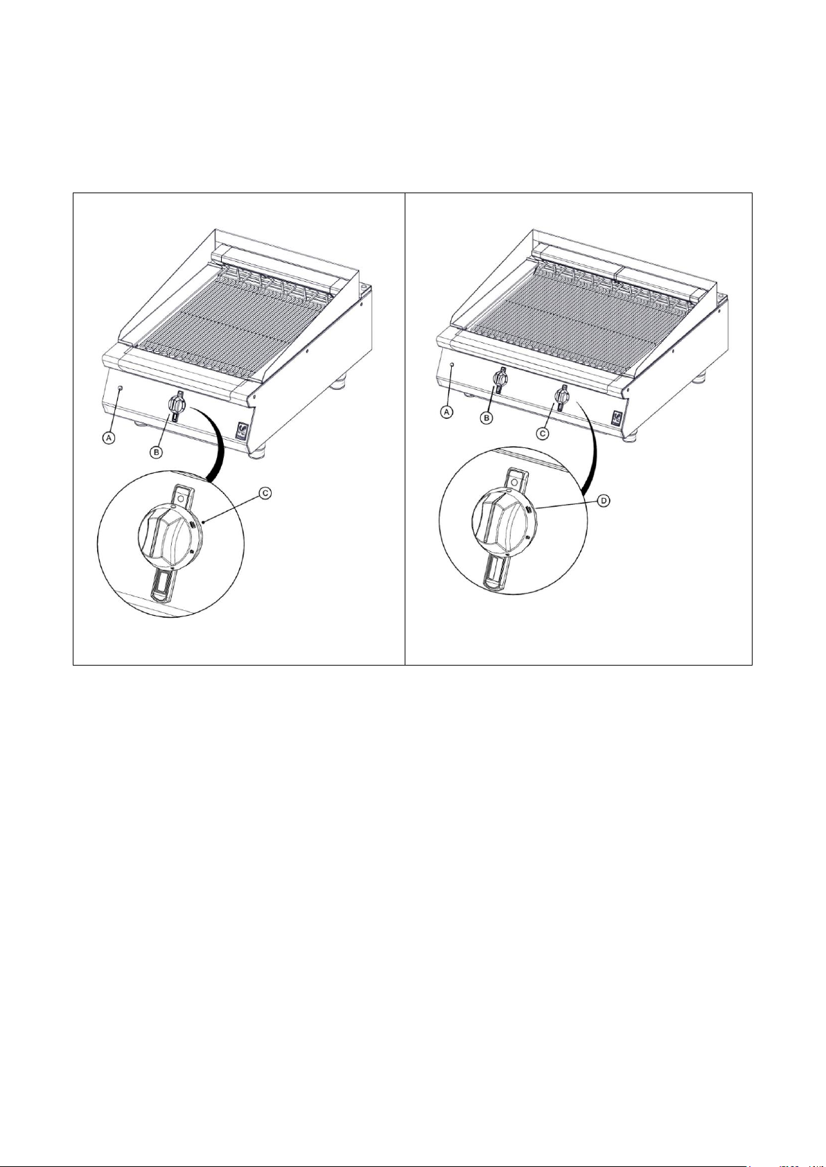
E9460
E9490
A -
Power neon (Red)
A-
Power neon (Red)
B -
Control
B-
Left hand control
C -
Cleaning setting
C-
Right hand control
D-
Cleaning setting
2.2 CONTROLS
10
Page 11
2.3 USING THE APPLIANCE
THE CLEAN SETTING IS USED FOR CLEANING ONLY, IN
THIS POSITION THE ELEMENTS CAN REACH 400°C.
DO NOT LEAVE THE CHARGRILL RUNNING ON A HIGH
SETTING FOR PROLONGED PERIODS WHEN NOT
COOKING.
TO MAINTAIN ELEMENT HEAT TURN THE CONTROL TO A
LOWER SETTING.
DO NOT PLACE NON-FOOD OBJECTS ON ELEMENTS,
INCLUDING METALLIC OBJECTS FOR EXAMPLE; POTS,
PANS OR UTENSILS AS THIS MAY CAUSE OVERHEATING
OF THE ELEMENTS AND LEAD TO A NON-WARRANTY
FAILURE.
2.3.1 Before use, clean the appliance inside and out. See section 3.
2.3.2 Ensure the drip tray is fitted.
2.3.3 Power Neon (red) will light when there is mains power to the appliance
2.3.4 The appliance is fitted with a numbered control knob which indicates regulator setting.
2.4 CHEF’S RECOMMENDATIONS
2.4.1 Element temperature must be regulated for different circumstances.
2.4.2 The food absorbs heat from the elements, when the chargrill is in continuous use and
cooking large quantities of food, it may be necessary to turn the control to a higher
setting than is normally required for smaller batches
2.4.3 Lightly oil the food item that is being cooked, prior to placing it on the pre-heated
element.
11
Page 12
3.0 CLEANING AND MAINTENANCE
BEFORE ANY CLEANING IS UNDERTAKEN, ISOLATE THE
APPLIANCE FROM MAINS POWER SUPPLY AT ISOLATOR
SWITCH.
SUITABLE PROTECTIVE CLOTHING MUST BE WORN WHEN
CLEANING THIS APPLIANCE.
THE APPLIANCE MUST NOT BE STEAM CLEANED. DO NOT
USE ACID OR HALOGEN-BASED (E.G. CHLORINE)
DESCALING LIQUIDS, FLAMMABLE LIQUIDS, CLEANING
AIDS OR CLEANING POWDERS.
FAILURE DUE TO LACK OF PROPER CLEANING IS NOT
COVERED BY WARRANTY.
When removing heavy items to aid cleaning or maintenance particular care should be taken.
A manual handling risk assessment is the best way to determine the level of risk to anyone
using or maintaining this equipment. To help with such an evaluation we have included the
weights of individual components that may present significant risk.
For further help and information on manual handling and associated risk assessment we
would refer you to you the Health and Safety Executive website; www.hse.gov.uk document
ref: manual handling at work INDG143. International customers should default to the health
and safety guidelines provided by your government body.
The cleaning of fryers or other products that use hot oil present significant risks to end users
and particular care should be taken. Cold water and hot oil for example are an explosive mix
and should be avoided at all costs.
Other useful references for health and safety issues:
www.hse.gov.uk
Essentials of health and safety at work ISBN978
Noise at work INDG362
Safe systems of work
Other notes added to the body of the instructions
NOTE: All surfaces are easier to clean if spillages are removed before becoming burnt on,
and the appliance is cleaned daily.
It should be noted that certain scouring pads including nylon types can easily mark stainless
steel. Care should be exercised during cleaning process. When rubbing stainless steel with
a cloth, always rub in the direction of the grain.
12
Page 13

3.1 CLEANING AND MAINTENANCE
ENSURE LOCKING PIN IS ENGAGED AND HOLDING
ELEMENTS UPRIGHT BEFORE CLEANING.
ENSURE THE ELEMENTS ARE COLD BEFORE RAISING
3.1.1 Turn the control knob to the cleaning setting.
3.1.2 Allow to run at maximum temperature for approximately 15 minutes.
3.1.3 At this setting most food debris should carbonize and fall off the elements.
3.1.4 Scrape off any remaining debris using the element cleaning tool provided.
3.1.5 When cold the elements may also be cleaned using a cloth and hot soapy water.
3.1.6 Lift the elements to the vertical position and engage locking pin.
13
Page 14

3.1.7 Clean the pan with warm water and detergent.
DO NOT USE COARSE ABRASIVES TO CLEAN EXTERIOR
PANELS. WARM WATER AND DETERGENT SOLUTION IS
RECOMMENDED.
DO NOT FORCE ELEMENTS DOWN WHILST LOCKING PIN
IS ENGAGED.
3.1.8 To clean the drip tray remove it from the appliance and warm water and detergent.
3.1.9 The splash guard is removable for cleaning.
3.1.10 The front and rear element support bars are also removable for cleaning.
3.1.11 To lower elements disengage locking pin and lower as required.
14
Page 15

3.1.12 If the unit is fitted with PTFE liners, ensure any debris that has collected behind the
THE PTFE SHEET SHOULD NOT BE ALLOWED TO COME
INTO CONTACT WITH THE ELEMENTS WHEN HOT.
DO NOT USE SHARP OR ABRASIVE MATERIALS TO CLEAN
THE PTFE SHEETING.
DISHWASHING THE PTFE SHEETING IS NOT
RECOMMENDED.
liners is removed on a daily basis.
3.1.13 The PTFE sheeting should be cleaned using non-corrosive agents. Warm water and
detergent is recommended.
3.2 PTFE FITTING
3.2.1 Remove Splashguards, front and rear PTFE Clamps and old PTFE Liner.
3.2.2 Lift the elements to the vertical position and engage locking pin.
3.2.3 Fit front & rear liners into appliance and fold PTFE to match the profile of the hob and
pan. Flatten any wrinkles or creases out of the liner against the hob and pan surfaces
as required.
15
Page 16

3.2.4 Re-fit PTFE Clamps, element support bars and splashguards as required.
APPLIANCE
UNIT WEIGHT (kg)
PACKED WEIGHT (kg)
E9460
49
62
E9490
60
77
E9460
CURRENT
POWER
PHASE
MIN (A) @
230V
MAX (A) @
230V
ACTUAL (A) @
230V
(kW) @ 230V
L1
10.00
11.67
11.11
3.36
L2
13.09
15.28
14.55
3.36
L3
10.00
11.67
11.11
1.68
E9490
CURRENT
POWER
PHASE
MIN (A) @
230V
MAX (A) @
230V
ACTUAL (A) @
230V
(kW) @ 230V
L1
13.09
15.28
14.55
3.36
L2
20.00
23.33
22.22
6.72
4.0 SPECIFICATION
4.1 APPLIANCE WEIGHT TABLE
4.2 TECHNICAL DATA TABLE
16
Page 17

L3
20.00
23.33
22.22
3.36
IF ANY CURRENT IS OUT WITH THESE TOLERANCES, THE
CAUSE MUST BE INVESTIGATED AND RECTIFIED.
5.0 DIMENSIONS / CONNECTION LOCATIONS
17
Page 18

6.0 INSTALLATION
ELECTRICAL SAFETY AND ADVICE REGARDING SUPPLEMENTARY ELECTRICAL
PROTECTION
18
Page 19

Commercial kitchens and foodservice areas are environments where electrical
IF SUITING, THE NECESSARY CLEARANCES TO ANY
COMBUSTIBLE WALL MUST BE THE LARGEST FIGURE
GIVEN FOR INDIVIDUAL APPLIANCE INSTRUCTIONS.
appliances may be located close to liquids, or operate in and around damp conditions
or where restricted movement for installation and service is evident.
The installation and periodic inspection of the appliance should only be undertaken
by a qualified, skilled and competent electrician; and connected to the correct power
supply suitable for the load as stipulated by the appliance data label.
The electrical installation and connections should meet the necessary requirements
to the local electrical wiring regulations and any electrical safety guidelines.
We recommend:-
Supplementary electrical protection with the use of a residual current device
(RCD)
Fixed wiring appliances incorporate a locally situated switch disconnector to
connect to, which is easily accessible for switching off and safe isolation
purposes. The switch disconnector must meet the specification requirements
of IEC 60947.
6.1 SITING / CLEARANCES
This appliance cannot be sited next to a combustible wall.
19
Page 20

6.2 ASSEMBLY
TAKE CARE WHEN MOVING AN APPLIANCE FITTED WITH
CASTORS.
Live 1 ( Phase 1)
Brown
Live 2 ( Phase 2)
Black
Live 3 ( Phase 3)
Grey
Neutral
Blue
Earth
Yellow/Green
6.2.1 Position the appliance and level using feet adjusters as shown below.
6.3 ELECTRIC SUPPLY & CONNECTION
The location of the electrical inlet is as seen in section 5.0. This unit is suitable for AC
supplies only. The standard terminal arrangement is Three phase (400V 3N~) for all
variants.
Install an appropriate three phase mains supply cable with a 32A plug.
To install the mains cable, remove rear access panel as shown in section 7.1 and feed the
cable through and connect to the terminal block.
20
Page 21

THIS APPLIANCE MUST BE EARTHED
This appliance is also provided with a terminal for connection of an
external equipotential conductor. This terminal is an effective electrical
contact with all fixed exposed metal parts of the appliance, and shall
allow the connection of conductor having a nominal cross-section area
of up to 10mm². It is located at the rear of the unit and identified by the
following label and must only be used for bonding purposes.
PLEASE FILL OUT THE INFORMATION TABLE ON THE
FRONT COVER AFTER COMMISSIONING.
6.4 COMMISSIONING
Refer to section 2.0 for operation. Carry out the following operation:
6.4.1 Turn on mains power supply on.
6.4.2 Ensure red neon illuminates.
6.4.3 Turn control knob to the clean setting.
6.4.4 Let the appliance heat up. At this setting the chargrill is constantly on and can reach
temperatures up to 400oC.
6.4.5 Switch appliance off.
If the appliance does not operate correctly please refer to section 9.0 and rectify the
problem.
21
Page 22

6.5 SUITING
The DLS system Patent no. GB 2540131 is designed to give a quick and easy suiting
solution. If you require an improved seal between appliances we recommend you use,
a food grade, high temperature silicon sealant. This can be supplied by Falcon part no
– 523400021
6.5.1 Before levelling and suiting units ensure the units are fully built, including all
accessories and castings.
6.5.2 Undo the 4 fixing screws on the control panel and remove.
6.5.3 Remove the hob rear infill and replace with rear suiting plate and fixings.
6.5.4 Remove the front side panel countersunk screw and suiting plate.
22
Page 23

6.5.5 Run a bead of silicon 5mm from profile edge as highlighted below.
6.5.6 Slide suited units into position.
6.5.7 (A) Right hand unit: Screw the M5 x 40 screw (supplied in the kit) into one of the
suiting plates as shown and then insert through the front fixing holes of both units.
6.5.8 (B) Left hand unit: Slide the penny and lock washer on to the screw and secure using
the M5 nut.
6.5.9 (C) Remove the front bolts from feet, insert base tie plate and secure the bolts back
into position.
23
Page 24

6.5.10 (D) Replace fixings on the rear hob and tighten screw caps into position.
6.5.11 Replace control panel.
24
Page 25

7.0 SERVICING
BEFORE ATTEMPTING ANY MAINTENANCE, ISOLATE THE
APPLIANCE AT THE MAINS SWITCH AND TAKE STEPS TO
ENSURE THAT IT IS NOT INADVERTENTLY SWITCHED ON.
THERE ARE NO SERVICEABLE COMPONENTS LOCATED
IN THE ELEMENT HEAD. THE MICRO SWITCH IS LOCATED
IN THE PIVOT HOUSING OF THE ELEMENT ASSEMBLY AS
SHOWN IN STEP 7.5.
THE ELEMENT HEAD IS A NON SERVICEABLE
COMPONENT. REMOVING THE ELEMENTS FROM THE
ELEMENT HEAD OF THE APPLIANCE WILL UNSEAT THE
GASKET. THIS WILL LEAD TO THE INGRESS OF FOOD AND
GREASE DEBRIS INTO THE ELEMENT HEAD ASSEMBLY.
IF THERE IS A FAULT WITH THE ELEMENTS ON THE
APPLIANCE THE COMPLETE ELEMENT HEAD ASSEMBLY
SHOULD BE REPLACED AS INSTRUCTED BELOW IN STEP
7.6.
25
Page 26

7.1 ACCESS PANEL REMOVAL
7.1.1 Remove access panel as shown below.
7.2 CONTROL PANEL REMOVAL
7.2.1 Remove control panel as shown below.
26
Page 27

7.3 ENERGY REGULATOR, SWITCH AND NEON REMOVAL
7.3.1 Remove control panel as shown in section 7.2.1
7.3.2 Remove energy regulator and switch as shown below.
7.3.3 Remove neon as shown below.
27
Page 28

7.4 CONTACTOR REMOVAL
7.4.1 Remove control panel as shown in section 7.2.1
7.4.2 Remove contactor as shown below.
7.5 MICRO SWITCH REMOVAL
7.5.1 Remove splashguards and rear panel as show below
28
Page 29

7.5.2 Remove two hex screws from each side of underside of the hob. Pull back pin and
remove element head end covers from the topside of hob and repeat on opposite side
if required.
7.5.3 Disconnect the wires from micro switch and unfasten two cap screws to remove micro
switch.
7.6 HEATING ELEMENTS REMOVAL
7.6.1 Remove splashguard, rear panel and element head end covers as shown in section
7.5.1 and 7.5.2.
7.6.2 Remove control panel as shown in section 7.2.1.
7.6.3 Remove element wires from contactor(s).
7.6.4 Remove three hex nuts on each end of the element mounting plates. E9490 version
will require the centre pillar nuts to be removed.
29
Page 30

7.6.5 Feed cables from front of unit and out at rear cable entry hole to enable element
assembly lift off as shown below.
30
Page 31

7.7 CIRCUIT DIAGRAMS
7.7.1 E9490 Circuit Diagram
31
Page 32

7.7.2 E9460 Circuit Diagram
32
Page 33

7.8 WIRING DIAGRAMS
7.8.1 E9490 Wiring Diagram
33
Page 34

7.8.2 E9460 Wiring Diagram
34
Page 35

8.0 ACCESSORIES
FAULT
POSSIBLE CAUSES
REMEDY
USER
*ENG
Unit will not turn ON
No power to unit
Check mains power is
connected and turned on
Heating elements will not
turn ON
Element not fully
down.
Ensure element is fully
lowered
Fuse has blown
Check Fuse behind
control panel (section
7.2.1) and replace as
necessary.
PROBLEM
POSSIBLE CAUSES
REMEDY
USER
*ENG
Food keeps burning
Dial setting too high
Lower dial setting
Appliance is too hot
Dial left on ‘Clean’
setting for too long.
Only use clean setting for
short periods and only
when cleaning the
appliance.
Appliance being left on
higher settings when
not in use.
If the appliance is not in
use, turn the dial to a
lower setting to maintain
element temperature.
9.0 FAULT FINDING
*ENG Service engineer only.
35
Page 36

PART DESCRIPTION
SPARES NUMBER
Power neon red
730962010
Control knob
733650003
Terminal Block
731000006
Contactor
734310440
Switch
732910481
Micro switch
735960015
Cleaning tool scraper
733650009
Energy regulator
737630011
E9460 Control panel
733650000
E9460 PTFE front & rear liner set
733650004
E9460 Element
735950000
E9460 Drip Tray
533550002
E9490 Control panel
733660000
E9490 PTFE front & rear liner set
733660002
E9490 Element
735960000
E9490 Drip Tray
533570000
10.0 SPARE PARTS
When ordering spare parts please quote the following:
Model Number
Serial number
This information will be found on data plate attached to the appliance
Visit our website for further spares information.
36
Page 37

11.0 SERVICE INFORMATION
It is recommended to have a maintenance contract with a local service provider.
SERVICELINE CONTACT:
(UK only)
Phone: +441438 363 000
Warranty Policy Shortlist
For our warranty policy please go to www.falconfoodservice.com
37
 Loading...