

Page 1

1
F900 SERIES
User, installation and servicing instructions
ELECTRIC SINGLE
WELL FRYER
E9341, E9341F
Read these instructions before use
T100949
REV. 1
Published: 27/09/16
DATE PURCHASED:
MODEL NUMBER:
SERIAL NUMBER:
DEALER:
SERVICE PROVIDER:
Page 2

2
Falcon Foodservice Equipment
HEAD OFFICE
Wallace View, Hillfoots Road, Stirling. FK9 5PY. Scotland.
WEEE Directive Registration No. WEEE/DC0059TT/PRO
At end of appliance life, dispose of appliance and any replacement parts in a safe
manner, via a licensed waste handler. Appliances are designed to be dismantled
easily and recycling of all material is encouraged whenever practicable.
Dear Customer,
Thank you for choosing Falcon Foodservice Equipment.
This manual can be downloaded from www.falconfoodservice.com or scan
here
IMPORTANT: Please keep this manual for future reference.
Page 3

3
SYMBOLS
• SPANNER • SCREWDRIVER • COOKING OIL • GREASE
• SPARK IGNITION • FLAME • WARNING • VIEWPORT
• ALLEN KEY • IGNITER •C SPANNER
Page 4

4
This appliance may be discoloured due to testing.
These instructions are only valid if the country code appears on the appliance. If the
code does not appear on the appliance, refer to the technical instructions for
adapting the appliance to the conditions for use in that country.
Installation must meet national or local regulations. Attention must be paid to: safety
(installation & use) regulations, health and safety at work act, local and national
building regulations, fire precautions act.
To prevent shocks, this appliance must be earthed.
This unit is fitted with an equipotential connection at the rear on the base.
This appliance has been CE-marked on the basis of compliance with the Low
Voltage and EMC Directives for the voltages stated on the data plate.
This equipment is for professional use only and must be used by qualified persons.
The installer must instruct the responsible person(s) of the correct operation and
maintenance of the appliance.
Unless otherwise stated, parts which have been protected by the manufacturer must
not be adjusted by the installer.
Take care when moving an appliance fitted with castors.
The appliance must be serviced regularly by a qualified person. Service intervals
should be agreed with the service provider.
Check that no damage has occurred to the appliance or supply cord during transit. If
damage has occurred, do not use this appliance.
Installation, periodic testing, repair and fixed wiring connections should only be
undertaken by a competent electrician.
Ensure the supply cord is routed free from the appliance to avoid damage.
We recommend supplementary electrical protection with the use of a residual
current device (RCD).
The appliance has been designed and approved to use Falcon kick plates; non
Falcon kick plates could potentially adversely affect the performance of the
appliance by restricting the air to the appliance.
All apparatus connected to a potable water network and including water drain device
has to be provided with an air break before its discharge to the drainage system.
Type AA.
Page 5

5
CONTENTS
1.0 APPLIANCE INFORMATION ..................................................................................... 7
2.0 OPERATION .............................................................................................................. 8
2.1 COMPONENT PARTS ............................................................................................ 8
2.2 CONTROLS .......................................................................................................... 10
2.3 USING THE FRYER – NORMAL OPERATION .................................................... 11
2.4 USING THE FRYER – ECO MODE ...................................................................... 13
2.5 USING THE FRYER – FAT MELT ........................................................................ 13
2.6 FILTRATION ......................................................................................................... 13
3.0 CLEANING AND MAINTENANCE ............................................................................ 14
4.0 SPECIFICATION ...................................................................................................... 18
5.0 DIMENSIONS / CONNECTION LOCATIONS ........................................................... 19
6.0 INSTALLATION ........................................................................................................ 20
6.1 SITING / CLEARANCES ....................................................................................... 20
6.2 ASSEMBLY .......................................................................................................... 20
6.3 ELECTRIC SUPPLY & CONNECTION ................................................................. 21
6.4 COMMISSIONING ................................................................................................ 22
6.5 SUITING ............................................................................................................... 23
7.0 SERVICING ............................................................................................................. 25
7.1 DOOR REMOVAL................................................................................................. 25
7.2 CONTROL PANEL REMOVAL (REMOVE DOOR FIRST) .................................... 25
7.3 TEMPERATURE CONTROL & NEONS REMOVAL ............................................. 26
7.4 SWITCH BOX FRONT PANEL REMOVAL ........................................................... 26
7.5 MODE CONTROL, PUMP SWITCH & SAFETY THERMOSTAT REMOVAL ........ 27
7.6 OPERATING AND SAFETY THERMOSTAT SENSOR REMOVAL ...................... 28
7.7 TERMINAL BLOCK ACCESS PANEL REMOVAL ................................................ 29
7.8 WIRE ACCESS PANEL REMOVAL ...................................................................... 29
7.9 CONTACTOR REMOVAL ..................................................................................... 30
7.10 ELEMENT ROTATING HANDLE REMOVAL ........................................................ 31
7.11 HEATING ELEMENTS AND MICROSWITCH REMOVAL .................................... 33
7.12 PUMP & TIMER REMOVAL (FROM FRONT) ....................................................... 34
7.13 PUMP & TIMER REMOVAL (FROM REAR) ......................................................... 35
7.14 PUMP TIMER SETTINGS FOR 230V ................................................................... 36
7.15 CIRCUIT DIAGRAMS ........................................................................................... 37
Page 6

6
7.16 WIRING DIAGRAMS ............................................................................................ 39
8.0 ACCESSORIES ....................................................................................................... 41
8.1 FULL SIZE BASKET ............................................................................................. 41
8.2 SPLASHGUARD ................................................................................................... 41
8.3 OIL RETURN HOSE ............................................................................................. 42
9.0 FAULT FINDING ...................................................................................................... 42
10.0 SPARE PARTS ........................................................................................................ 43
11.0 SERVICE INFORMATION ........................................................................................ 44
Page 7
7
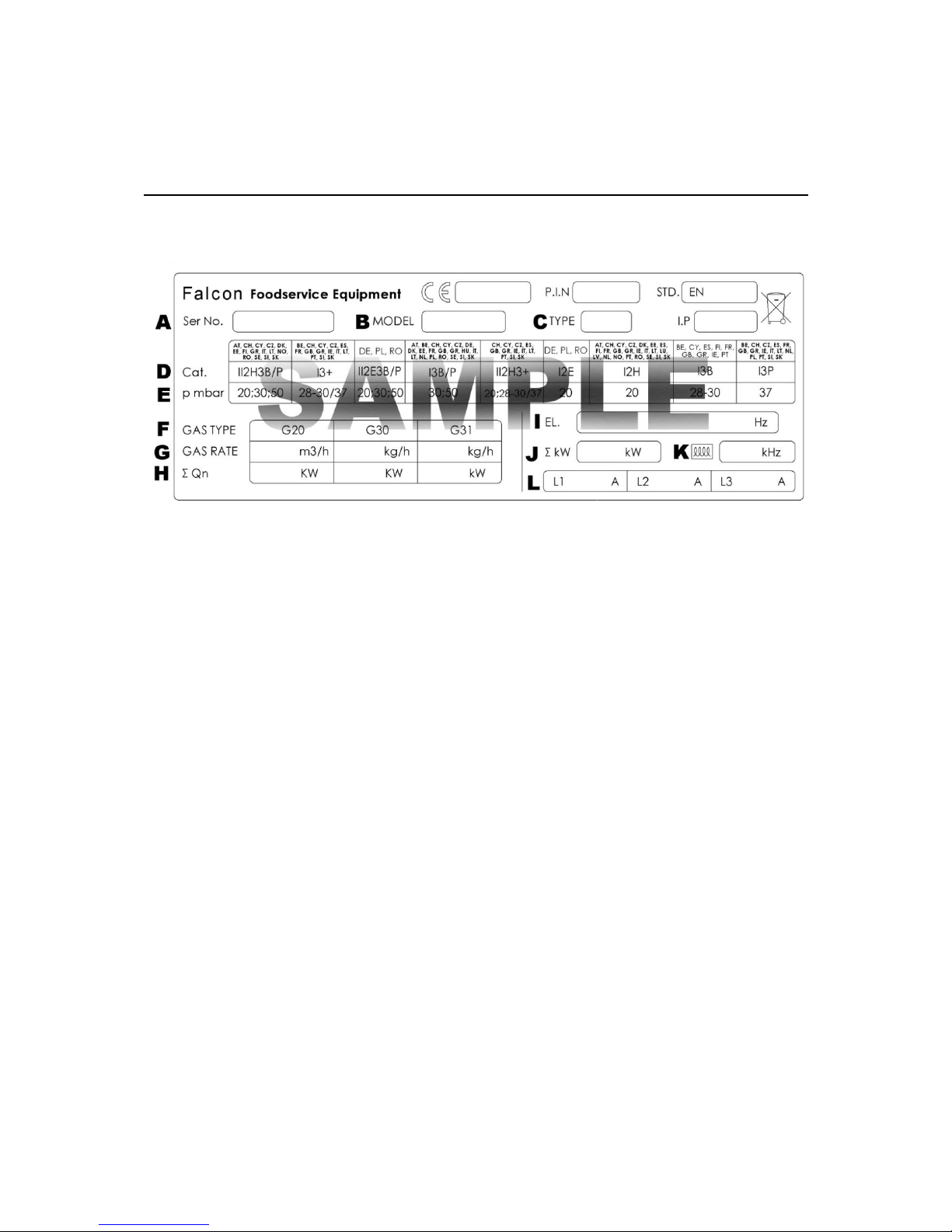
1.0 APPLIANCE INFORMATION
This appliance has been CE-marked on the basis of compliance with the relevant EU
directives for the heat inputs, gas pressures and voltages stated on the data plate.
A - Serial No
B - Model No
C - Flue Type
D - Gas Category
E - Gas Pressure
F - Gas Type
G - Gas Rate
H - Total Heat Input
I - Electrical Rating
J - Total Electrical Power
K - Magnetic Field Frequency
L - Electrical Phase Loading
Page 8
8
2.0 OPERATION
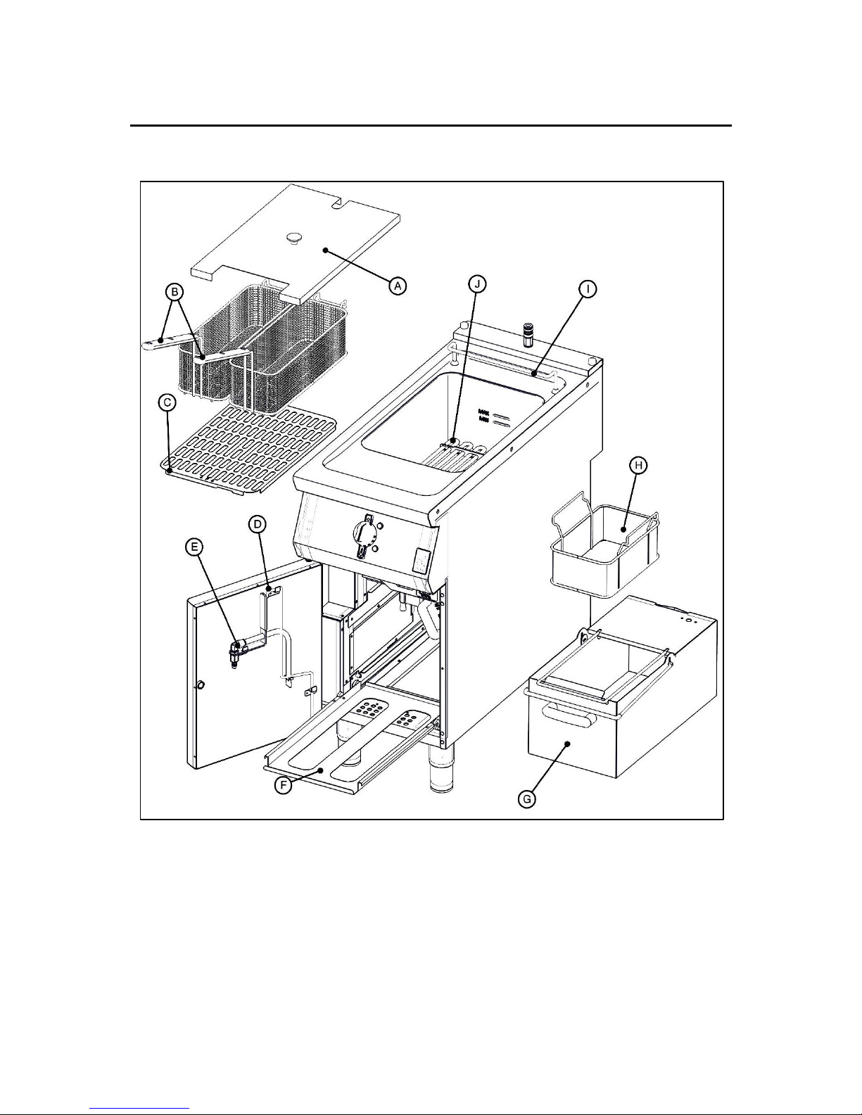
2.1 COMPONENT PARTS
A – Dust Cover F – Bucket Runner Cradle
B – Half Baskets (2 Off) G – Oil Bucket
C – Fry Plate H – Filtration Basket and Mesh Filter
D – Drain Prod / Lifting / Scraping Tool I – Basket Hanger
E – Oil Return Pipe J – Heating Elements
(E9341F Only)
Page 9
9
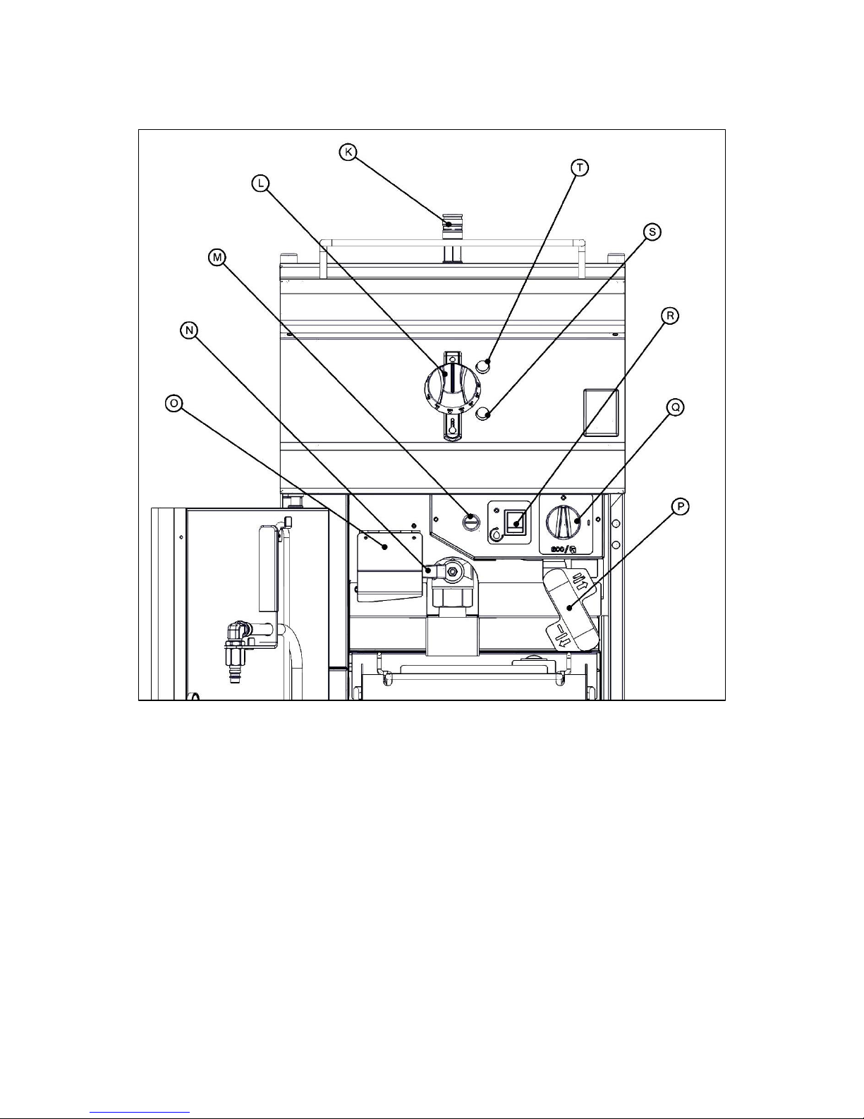
K – Quick Release Connection P – Element Rotating Handle
(E9341F Only)
L – Temperature Control Q – Mode Control
M – Safety Thermostat Reset R – Filtration Pump Switch
(E9341F Only)
N – Drain Valve S – Heat Demand Neon (Amber)
O – Drain Valve Safety Flap T – Power Neon (Red)
Page 10
10
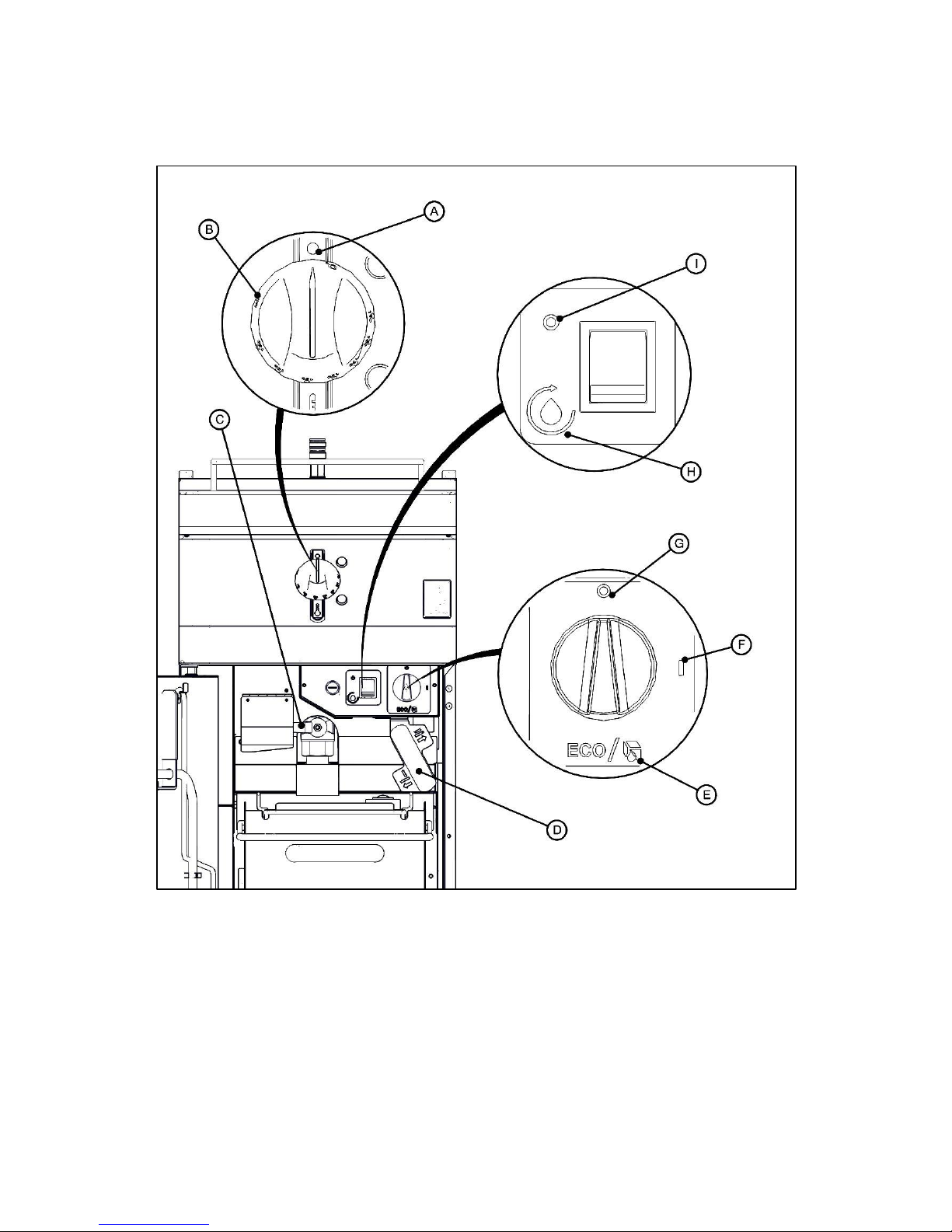
2.2 CONTROLS
A – TEMPERATURE CONTROL F – ELEMENT ON
OFF POSITION
B – TEMPERATURE CONTROL G – ELEMENT OFF
MINIMUM MARK
C – DRAIN VALVE CLOSED POSITION H – FILTRATION PUMP ON
D – ELEMENTS DOWN POSITION I – FILTRATION PUMP OFF
E – ECO/FAT MELT MODE
Page 11
11
2.3 USING THE FRYER – NORMAL OPERATION
2.3.1 Before use, clean the appliance inside and out. See section 3.0.
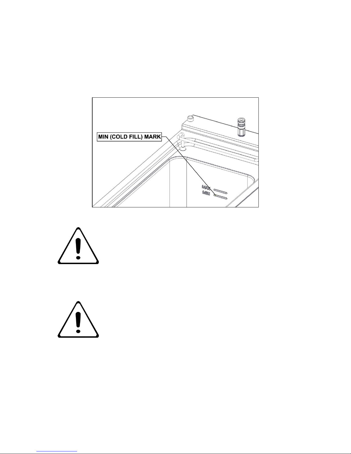
2.3.2 Ensure drain valve is closed. Fill pan with cold cooking medium to -MIN- (cold fill)
mark as shown below. Once cooking medium is hot, it will expand and reach the –
MAX- (hot oil) mark.
MIN- LEVEL MARK: NEVER FILL COLD COOKING MEDIUM ABOVE
THIS MARK. DURING COOKING, MEDIUM SHOULD NEVER BE
ALLOWED TO DROP BELOW THIS MARK. SHOULD THIS OCCUR,
TOP UP IMMEDIATELY OR SWITCH FRYER OFF.
MAX- LEVEL MARK: NEVER ALLOW COOKING MEDIUM TO GO
ABOVE THIS MARK.
SUITABLE PROTECTIVE CLOTHING MUST BE WORN WHEN
TOPPING UP WHILST OIL IN FRYER IS HOT.
OLD OIL WILL HAVE A REDUCED FLASH-POINT AND BE PRONE
TO SURGE BOILING.
NEVER ADD WATER TO FRYING MEDIUM AT ANY TIME!
2.3.3 Power Neon (red) will light when there is mains power to the appliance.
2.3.4 Turn Mode Control Knob to “Element On”.
2.3.5 Turn Temperature Control Knob to desired temperature. Heat Demand Neon (amber)
will light as the heating elements heats the cooking medium. Heat Demand Neon
(amber) and the heating elements will turn off when the set temperature is reached.
Page 12
12
2.3.6 For optimum cooking performance, use the recommended load and temperature
settings shown in the table below:
Food Product
Maximum
Kg / Half Basket
Maximum
Kg / Full Basket
Optimum
Oil Temperature oC
Pre-blanched chilled
fries
1.7*
3.4*
175
Frozen fries
1.25**
2.5**
185
* This equates to roughly filling the basket 1/2 way up.
** This equates to roughly filling the basket 1/3 way up.
OVERLOADING THE BASKETS WILL AFFECT THE FRYER
PERFORMANCE.
SETTING THE OIL TEMPERATURE ABOVE THE RECOMMENDED
VALUE MAY REDUCE THE LIFE OF OIL.
NEVER LEAVE A WORKING UNIT UNATTENDED.
NOTE: The fryer is fitted with a thermal safety device. This will stop the heating of the
medium if it becomes overheated. This appliance will always fail safe.
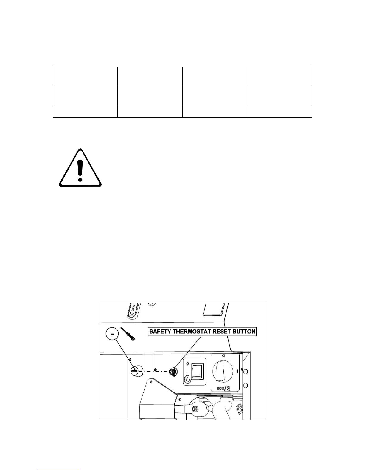
2.3.7 If the appliance unexpectedly turns off, the safety thermostat might have activated.
To reset it, follow the instructions below:
a) Turn Temperature Control Knob to “Off Position”
b) Turn Mode Control Knob to “Element Off”.
c) Allow oil to cool below 180°C.
d) Remove the black dust cover on the safety thermostat and reset the red button with
a pen or similar item as shown below.
e) Turn Mode Control Knob to “Element On”.
Page 13

13
f) Turn Temperature Control Knob to desired temperature.
g) If the safety thermostat reactivates call a qualified technician to carry out an
investigation.
2.3.8 To switch appliance off, turn Temperature Control Knob to “Off Position” and turn
Mode Control Knob to “Element Off”.
2.4 USING THE FRYER – ECO MODE
Use ECO mode for pre-heating. It will help to prolong the life of oil and reduce energy
consumption.
2.4.1 Turn Mode Control Knob to “ECO/Fat Melt Mode”.
2.4.2 Turn Temperature Control Knob to a suitable preheating temperature, e.g. 130oC.
2.5 USING THE FRYER – FAT MELT
2.5.1 Turn Mode Control Knob to “ECO/Fat Melt Mode”.
2.5.2 Turn Temperature Control Knob to “Minimum Mark”.
SOLID FAT (E.G. BEEF TALLOW) MUST BE MELTED USING THE
ECO/FAT MELT MODE IN ORDER TO AVOID FIRE CAUSED BY
BURNING OF THE FAT AND/OR OVERHEATING THE ELEMENT.
2.6 FILTRATION
2.6.1 Ensure the Heating Elements are turned off.
2.6.2 Wait 15/20 minutes to allow oil to cool.
2.6.3 Ensure Filtration Basket & Mesh Filter are clean and dry and locate them in the Oil
Bucket.
2.6.4 Ensure Oil Bucket is clean and dry. Place it on the Runner Cradle and slide it back
into the appliance until it engages with the pump.
2.6.5 Open drain valve and allow oil to drain from pan.
2.6.6 Attach the Oil Return Pipe by pushing it into the Quick Release Connection.
2.6.7 Switch on filtration pump.
2.6.8 Clear pan of debris as stated in section 3.6-3.8.
2.6.9 Cycle oil until pan is clear of debris.
2.6.10 Close drain valve and allow pan to fill.
2.6.11 Once Pan is full, switch off the filtration pump.
Page 14

14
2.6.12 After filtering wait 30 seconds before removing bucket.
CAUTION: HEAVY OIL BUCKET WHEN FULL! TAKE CARE WHEN
REMOVING THE BUCKET.
2.6.13 To remove the Oil Return Pipe, pull down on the Quick Release Connection and pull
off the Oil Return Pipe as shown below.
3.0 CLEANING AND MAINTENANCE
BEFORE ANY CLEANING IS UNDERTAKEN, ISOLATE APPLIANCE FROM MAINS
POWER SUPPLY AT ISOLATOR SWITCH.
SUITABLE PROTECTIVE CLOTHING MUST BE WORN WHEN CLEANING THIS
APPLIANCE.
NEVER PUMP WATER THROUGH THE FILTRATION PUMP AT ANY TIME!
OIL MUST BE ALLOWED TO COOL TO A SAFE TEMPERATURE BEFORE DRAINING.
DO NOT OVERFILL OIL BUCKET.
THE APPLIANCE MUST NOT BE STEAM CLEANED. DO NOT USE ACID OR
HALOGEN-BASED (E.G. CHLORINE) DESCALING LIQUIDS, FLAMMABLE LIQUIDS,
CLEANING AIDS OR CLEANING POWDERS.
FAILURE DUE TO LACK OF PROPER CLEANING IS NOT COVERED BY WARRANTY.
Page 15

15
Note: All surfaces are easier to clean if spillage is removed before it becomes burnt on,
cleaned daily.
It should be noted that certain scouring pads including nylon types can easily mark
stainless steel. Care should be exercised during cleaning process. When rubbing stainless
steel with a cloth, always rub in grain direction.
3.1
Switch appliance off and cool down.
3.2
Ensure Filtration Basket & Mesh Filter are located in the Oil Bucket. Place Oil Bucket
on the Runner Cradle and slide it back into the appliance until it engages with the
pump.
3.3
Turn Drain Valve to drain oil from pan as shown in below left.
3.4
Remove Baskets and Fry Plate. If the Fry plate is hot, use the Drain Prod/ Lifting /
Scraping Tool as shown in below left.
3.5
Use the Element Rotating Handle to rotate the Heating Elements up as shown below
right if required to clean pan.
3.6
Attach the Oil Return Pipe and switch on the filtration pump. Move Oil Return Pipe
from side to side to wash away debris.
Page 16

16
3.7
Use the scraping end (A) of the Drain Prod / Lifting / Scraping Tool as shown below
to scrape any debris in the pan down the drain. Use the drain prod end (B) to push
any debris down the drain if drain gets blocked.
3.8
It is recommended to use the accessory hose (see section 8.2) and switch on the
filtration pump to flush out the excess debris from hard to reach places.
3.9
After filtering wait 30 seconds before removing bucket.
3.10
Remove Oil Bucket by pulling it forward then lifting it upwards by the wire handle as
shown below.
CAUTION: HEAVY OIL BUCKET WHEN FULL! TAKE CARE WHEN
REMOVING THE BUCKET.
Page 17

17
3.11
Remove the Filtration Basket & Mesh Filter and discard the collected debris.
3.12
Empty oil from the Oil Bucket into a separate container. Replace the Oil Bucket back
in the fryer.
3.13
Soak Baskets, Fry Plate, Filtration Basket & Mesh Filter in hot soapy water.
3.14
Wash, rinse and dry above components thoroughly.
3.15
Close drain Valve and fill pan with hot soapy water to the MIN mark.
3.16
Clean pan with soft, clean cloth and rub away any stubborn staining with scouring
pad.
TAKE CARE NOT TO DISLODGE OR DAMAGE THERMOSTAT
SENSORS ON THE HEATING ELEMENTS AS SEEN IN SECTION
7.6.1.
3.17
Open Drain Valve to empty water into Oil Bucket.
3.18
Rinse pan and dry thoroughly.
3.19
Remove Oil Bucket and empty the water into the sink.
3.20
Wash, rinse and dry Oil Bucket thoroughly.
3.21
Rotate the Heating Elements back down using the Element Rotating Handle.
ALWAYS USE THE ELEMENT ROTATING HANDLE TO ROTATE
HEATING ELEMENTS. DO NOT ROTATE ELEMENTS BY HAND OR
ANY OTHER TOOL.
3.22
Close Drain Valve and replace all removed components. When replacing the Fry
Plate, ensure the “F” mark is towards the front of the appliance.
Page 18

18
4.0 SPECIFICATION
4.1 Appliance Weight Table
APPLIANCE
UNIT WEIGHT (kg)
PACKED WEIGHT (kg)
E9341
62
72
E9341F
70
80
4.2 Technical Data Table – E9341 & E9341F
CURRENT
POWER
PHASE
MIN (A) @
230V
MAX (A) @
230V
ACTUAL (A) @
230V
(kW) @ 230V
L1
24.75
28.88
27.5
6.33
L2
24.75
28.88
27.5
6.33
L3
24.75
28.88
27.5
6.33
IF ANY CURRENT IS OUT WITH THESE TOLERANCES, THE
CAUSE MUST BE INVESTIGATED AND RECTIFIED.
Page 19

19
5.0 DIMENSIONS / CONNECTION LOCATIONS
Page 20

20
6.0 INSTALLATION
6.1 SITING / CLEARANCES
This appliance can be sited next to a combustible wall.
IF SUITING THE NECESSARY CLEARANCES TO ANY COMBUSTIBLE
WALL MUST BE THE LARGEST FIGURE GIVEN FOR INDIVIDUAL
APPLIANCES INSTRUCTIONS.
6.2 ASSEMBLY
6.2.1 Position appliance and level using feet adjusters or castors as shown below.
Page 21

21
6.2.2 Appliance to be fixed to the floor using the supplied anti tilt device as shown below.
6.3 ELECTRIC SUPPLY & CONNECTION
The location of the electrical inlet is as seen in section 5.0. This unit is suitable for AC
supplies only. The standard terminal arrangement is Three phase (400V 3N~) for all
variants.
Live 1 ( Phase 1)
Brown
Live 2 ( Phase 2)
Black
Live 3 ( Phase 3)
Grey
Neutral
Blue
Earth
Yellow/Green
Install an appropriate Three phase mains supply cable with a 32A plug.
To install the mains supply cable, remove rear access panel as shown in section 7.13 and
feed the cable through to the front. Open Terminal Block Access Panel as shown in section
7.7 and connect the mains supply to the terminal block.
THIS APPLIANCE MUST BE EARTHED.
Page 22

22
6.4 COMMISSIONING
Refer to section 2.0 for operation. If safety thermostat is activated, refer to section 2.3.7 to
reset it.
6.4.1 Fill pan with cold oil to the MIN mark.
6.4.2 Turn mains power supply on.
6.4.3 Ensure red neon illuminates.
6.4.4 Turn elements on and turn temperature control knob to 190°C.
6.4.5 Ensure amber neon illuminates.
6.4.6 Rotate the heating elements up as shown in section 3.5.
6.4.7 Ensure amber neon switches off.
6.4.8 Rotate elements back down.
6.4.9 Ensure amber neon illuminates. If amber neon switches on and off by raising and
lowering the heating elements, the microwitch is operating correctly.
6.4.10 Let cooking oil heat up. When amber neon switches off, check the oil temperature in
the middle of the pan. Ensure it reaches between 190°C-210°C.
6.4.11 Switch appliance off.
This appliance is also provided with a terminal for connection of an external equipotential
conductor. This terminal is an effective electrical contact with all fixed exposed metal parts of
the appliance, and shall allow the connection of conductor having a nominal cross-section
area of up to 10mm². It is located at the rear of the unit and identified by the following label
and must only be used for bonding purposes.
If the appliance does not operate correctly please refer to section 9.0 and rectify the
problem.
PLEASE FILL OUT THE INFORMATION TABLE ON THE FRONT
COVER AFTER COMMISSIONING.
Page 23

23
6.5 SUITING
“Patent pending, application no. GB 1511389.7”
6.5.1 Before leveling and suiting units ensure the units are fully built, including all
accessories and castings.
6.5.2 Undo the 4 fixing screws on the control panel and remove.
6.5.3 Remove the hob rear infill and replace with rear suiting plate and fixings.
6.5.4 Remove the front side panel countersunk screw and suiting plate.
NOTE: The DLS system is designed to give a quick and easy suiting solution. If
you require an improved seal between appliances we recommend you
use, a food grade, high temperature silicon sealant. This can be
supplied by Falcon part no – 523400021
6.5.5 Run a bead of silicon 5mm from profile edge as highlighted below.
Page 24

24
6.5.6 Slide suited units into position.
6.5.7 Right hand unit: Screw the M5 x 40 screw (supplied in the kit) into one of the suiting
plates as shown and then insert through the front fixing holes of both units.
6.5.8 (B) Left hand unit: Slide the penny and lock washer on to the screw and secure using
the M5 nut.
6.5.9 (C) Remove the front bolts from feet, insert base tie plate and secure the bolts back
into position.
6.5.10 (D) Replace fixings on the rear hob and tighten screw caps into position.
6.6.10 Replace control panel.
A B C
D
Page 25

25
7.0 SERVICING
BEFORE ATTEMPTING ANY MAINTENANCE, ISOLATE THE
APPLIANCE AT THE MAINS SWITCH AND TAKE STEPS TO ENSURE
THAT IT IS NOT INADVERTENTLY SWITCHED ON.
7.1 DOOR REMOVAL
7.2 CONTROL PANEL REMOVAL (REMOVE DOOR FIRST)
All fuses are located behind the control panel.
Page 26

26
7.3 TEMPERATURE CONTROL & NEONS REMOVAL
7.4 SWITCH BOX FRONT PANEL REMOVAL
Page 27

27
7.5 MODE CONTROL, PUMP SWITCH & SAFETY THERMOSTAT REMOVAL
WHEN REPLACING THE MODE CONTROL SWITCH, THE COPPER
LINK BETWEEN TERMINALS 4 & 5 MUST BE REMOVED AS SHOWN
BELOW.
Page 28

28
7.6 OPERATING AND SAFETY THERMOSTAT SENSOR REMOVAL
7.6.1 Replace thermostat sensors onto the heating elements clip as shown below. Ensure
the distance from the end of the heating elements to the tip of the operating
thermostat “A” is 167mm and to the tip of the safety thermostat sensor “B” is 177mm.
Page 29

29
7.7 TERMINAL BLOCK ACCESS PANEL REMOVAL
7.8 WIRE ACCESS PANEL REMOVAL
Page 30

30
7.9 CONTACTOR REMOVAL
7.9.1 First remove the Bucket Cover (A) as shown. Remove screws and pull the panel
slightly forward to clear the locating lugs at the rear then drop it down and slide the
whole assembly forward.
7.9.2 Now remove contactor cover and the contactors as shown.
Page 31

31
7.9.3 Replace components in reverse order.
TAKE CARE NOT TO TRAP ANY WIRES WHEN REPLACING THE
BUCKET COVER IN PLACE.
7.10 ELEMENT ROTATING HANDLE REMOVAL
7.10.1 First remove the switch box as shown.
7.10.2 Then remove drain cover as shown.
Page 32

32
7.10.3 Then remove the pan front cover as shown.
7.10.4 Now remove the element rotating handle as shown.
Page 33

33
7.11 HEATING ELEMENTS AND MICROSWITCH REMOVAL
7.11.1 First remove the element rotating handle. Then remove microswitch rod (A) as
shown. Then remove the locking nut (B) and pull forward to remove the microswitch
assembly (C) as shown. Now pull out the heating elements (D) into the pan to
remove as shown.
7.11.2 When replacing the elements, ensure to apply food grade grease around the O-rings
as shown below. This grease can be supplied by Falcon part No. 0000000.
Page 34

34
7.12 PUMP & TIMER REMOVAL (FROM FRONT)
7.12.1 First remove the bucket cover as shown in 7.9.1. Then remove the bucket runner
cradle as shown.
7.12.2 Then remove pipe connection from the pump and right hand runner support fixing
screws as shown.
Page 35

35
7.12.3 Now pull forward the right hand runner support assembly and remove the pump and
timer as shown.
7.13 PUMP & TIMER REMOVAL (FROM REAR)
7.13.1 First remove rear access panel as shown.
7.13.2 Now remove pump and timer as shown in 7.12.3.
Page 36

36
7.14 PUMP TIMER SETTINGS FOR 230V
7.14.1 Set top function to “0.8”.
7.14.2 Set middle function to “10” minutes
7.14.3 Set base function set to “Wu”.
Page 37

37
7.15 CIRCUIT DIAGRAMS
7.15.1 E9341 Circuit Diagram
Page 38

38
7.15.2 E9341F Circuit Diagram
Page 39

39
7.16 WIRING DIAGRAMS
7.16.1 E9341 Wiring Diagram
Page 40

40
7.16.2 E9341F Wiring Diagram
Page 41

41
8.0 ACCESSORIES
8.1 FULL SIZE BASKET
8.2 SPLASHGUARD
8.2.1 Place splashguard on top of the unit as shown.
Page 42

42
8.3 OIL RETURN HOSE
8.3.1 Attach drain hose to the quick release connection as shown. On the other end of the
drain hose, attach the oil return pipe as shown.
9.0 FAULT FINDING
FAULT
POSSIBLE CAUSES
REMEDY
Unit will not turn ON
No power to unit
Check mains power is
connected and turned on
Safety thermostat
activated
Overheating
Allow to cool below 180°c
Safety thermostat
activated
Low oil level
Add oil to min level mark
Pump stops running
Pump has ran cycle
Allow the pump to cool
and then run once more
Pump stops running
Blocked pump
Clean Filters Regularly
Heating elements will not
turn ON
Safety thermostat has
tripped.
Reset safety thermostat.
Fuse has blown.
Check fuse behind
control panel and replace
as necessary.
Page 43

43
10.0 SPARE PARTS
PART DESCRIPTION
SPARES NUMBER
Power neon red
730962010
Heat demand neon amber
730962040
Operating thermostat
731300190
Temperature control knob
733500011
Safety thermostat
731350021
Mode control switch C/W knob
733500017
Filtration pump
536300054
Filtration pump switch kit
733500013
Pump timer
536470007
Fine mesh filter
737101159
Filtration basket
535770032
Half baskets
733500001
Fry plate
733500002
Oil return pipe assembly (E9341F only)
733500003
When ordering spare parts please quote the following;
Model Number
Serial number
This information will be found on data plate attached to the appliance
Visit our website for further spares information.
PROBLEM
POSSIBLE CAUSES
REMEDY
Surge Boiling
Over loading with wet food
Reduce the amount of
wet food
Overloading with oil
Reduce the amount of
oil to the Min Level
Pan Not Draining
Blocked with debris
Clean drain hole
Oil not Filtering
Blocked filters with debris
Clean filters inside the
oil bucket
Debris is being returned
to pan after filtering
Blocked filters in fryer
bucket and overflowing,
allowing unfiltered oil back
to pan
Ensure oil has time to
filter through strainer.
Heavily unfiltered oil can
block pump
Page 44

44
11.0 SERVICE INFORMATION
It is recommended to have a maintenance contract with a local service provider.
SERVICELINE CONTACT:
(UK only)
Phone: +441438 363 000
Warranty Policy Shortlist
For our warranty policy please go to www.falconfoodservice.com
 Loading...