

Falcon E9241, F900 Series User, Installation And Servicing Instructions

F900 SERIES
User, installation and servicing instructions
PASTA COOKER
E9241
T100900
Rev 9
Published: 02/10/2018
DATE PURCHASED:
MODEL NUMBER:
SERIAL NUMBER:
DEALER:
SERVICE PROVIDER:
Read these instructions before use
WEEE Directive Registration No. WEEE/DC0059TT/PRO
At end of appliance life, dispose of appliance and any replacement parts in a
safe manner, via a licensed waste handler. Appliances are designed to be
dismantled easily and recycling of all material is encouraged whenever
practicable.
Dear Customer
Thank you for choosing Falcon Foodservice Equipment.
This manual can be downloaded from www.falconfoodservice.com or scan
here:
IMPORTANT: Please keep this manual for future reference.
Falcon Foodservice Equipment
HEAD OFFICE
Wallace View, Hillfoots Road, Stirling. FK9 5PY. Scotland.

SCREWDRIVER
SPANNER
COOKING OIL
GREASE
WARNING
SPARK IGNITION
FLAME
VIEWPORT
ALLEN KEY
IGNITER
C SPANNER
SYMBOLS

This appliance may be discoloured due to testing.
These instructions are only valid if the country code appears on the appliance. If
the code does not appear on the appliance, refer to the technical instructions for
adapting the appliance to the conditions for use in that country.
Installation must meet national or local regulations. Attention must be paid to:
safety (installation & use) regulations, health and safety at work act, local and
national building regulations, fire precautions act.
To prevent shocks, this appliance must be earthed.
This unit is fitted with an equipotential connection at the rear on the base.
This appliance has been CE-marked on the basis of compliance with the Low
Voltage and EMC Directives for the voltages stated on the data plate.
This equipment is for professional use only and must be used by qualified
persons.
The installer must instruct the responsible person(s) of the correct operation and
maintenance of the appliance.
Unless otherwise stated, parts which have been protected by the manufacturer
must not be adjusted by the installer.
Take care when moving an appliance fitted with castors.
The appliance must be serviced regularly by a qualified person. Service intervals
should be agreed with the service provider.
Check that no damage has occurred to the appliance or supply cord during transit.
If damage has occurred, do not use this appliance.
Installation, periodic testing, repair and fixed wiring connections should only be
undertaken by a competent electrician.
Ensure the supply cord is routed free from the appliance to avoid damage.
We recommend supplementary electrical protection with the use of a residual
current device (RCD).
The appliance has been designed and approved to use Falcon kick plates; non
Falcon kick plates could potentially adversely affect the performance of the
appliance by restricting the air to the appliance.
All apparatus connected to a potable water network and including water drain
device has to be provided with an air break before its discharge to the drainage
system. Type AA.

CONTENTS
1.0 APPLIANCE INFORMATION ..................................................................................... 1
2.0 OPERATION .............................................................................................................. 2
2.1 COMPONENT PARTS ......................................................................................... 2-3
2.2 CONTROLS ............................................................................................................ 4
2.3 USING THE APPLIANCE ....................................................................................... 5
3.0 CLEANING AND MAINTENANCE ............................................................................. 6
3.1 CLEANING AND MAINTENANCE .......................................................................... 6
4.0 SPECIFICATION ........................................................................................................ 7
4.1 APPLIANCE WEIGHT TABLE ................................................................................ 7
4.2 TECHNICAL DATA TABLE ..................................................................................... 7
5.0 DIMENSIONS / CONNECTION LOCATIONS ............................................................ 8
6.0 INSTALLATION ......................................................................................................... 9
6.1 SITING / CLEARANCES ......................................................................................... 9
6.2 ASSEMBLY .......................................................................................................... 10
6.3 ELECTRIC SUPPLY & CONNECTION ................................................................. 11
6.4 COMMISSIONING ................................................................................................ 11
6.5 SUITING .......................................................................................................... 12-14
7.0 SERVICING ............................................................................................................. 15
7.1 DOOR REMOVAL................................................................................................. 15
7.2 TEMPERATURE CONTROL & TAP REMOVAL ................................................... 16
7.3 CONTROL PANEL REMOVAL ............................................................................. 16
7.4 SWITCH PANEL REMOVAL ................................................................................. 17
7.5 OPERATING & SAFETY STAT REMOVAL .......................................................... 17
7.6 ELEMENT COVER REMOVAL ............................................................................. 18
7.7 ELEMENT REMOVAL ..................................................................................... 18-19
7.8 TAP REMOVAL .................................................................................................... 20
7.9 CIRCUIT DIAGRAMS ...................................................................................... 21-22
7.10 WIRING DIAGRAMS ....................................................................................... 23-24
8.0 ACCESSORIES ....................................................................................................... 24
8.1 BASKETS AND BASE PANEL ......................................................................... 24-26
9.0 FAULT FINDING ...................................................................................................... 25
10.0 SPARE PARTS ........................................................................................................ 26
11.0 SERVICE INFORMATION ........................................................................................ 26
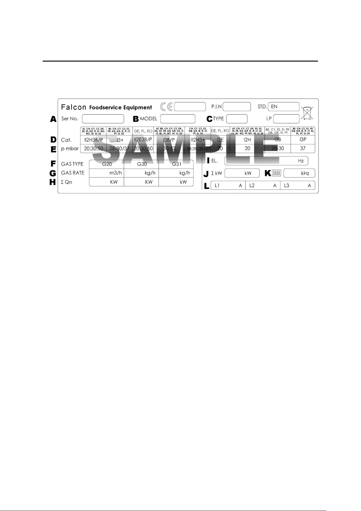
1.0 APPLIANCE INFORMATION
This appliance has been CE-marked on the basis of compliance with the relevant EU
directives for the heat inputs, gas pressures and voltages stated on the data plate.
A - Serial No
B - Model No
C - Flue Type
D - Gas Category
E - Gas Pressure
F - Gas Type
G - Gas Rate
H - Total Heat Input
I - Electrical Rating
J - Total Electrical Power
K - Magnetic Field Frequency
L - Electrical Phase Loading
1
2.0 OPERATION
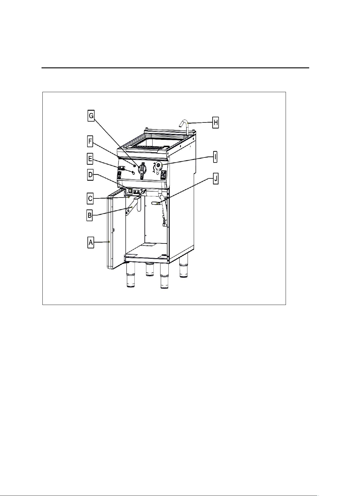
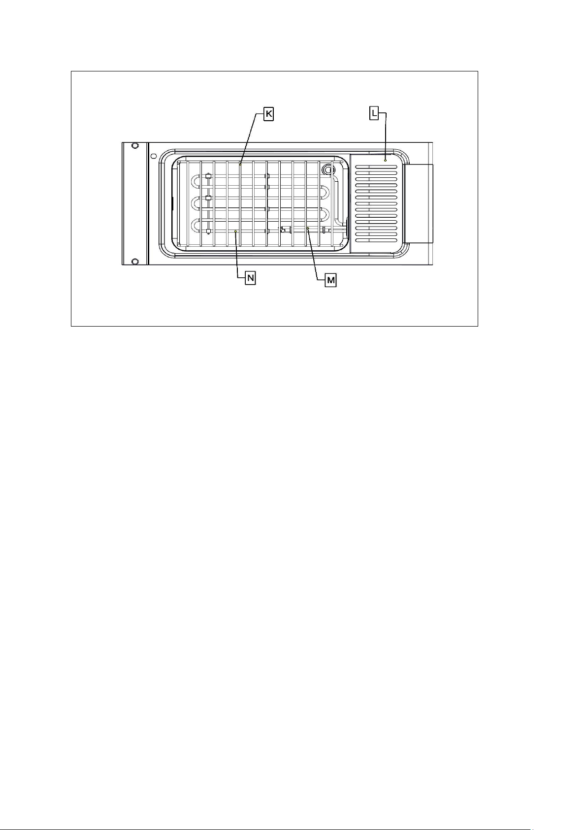
2.1 COMPONENT PARTS
2
A -
DOOR
H -
FILLER SPOUT
B -
ELEMENT ROTATING HANDLE
I -
WATER TAP
C -
RESET SWITCH
J -
DRAIN HANDLE CLOSED
D -
ON/OFF SWITCH
K -
WIRE GRID
E -
POWER NEON
L-
DRAIN SHELF
F -
HEAT DEMAND NEON
M-
SAFETY & OPERATING THERMOSTAT
G -
TEMPERATURE CONTROL
N-
ELEMENT
3
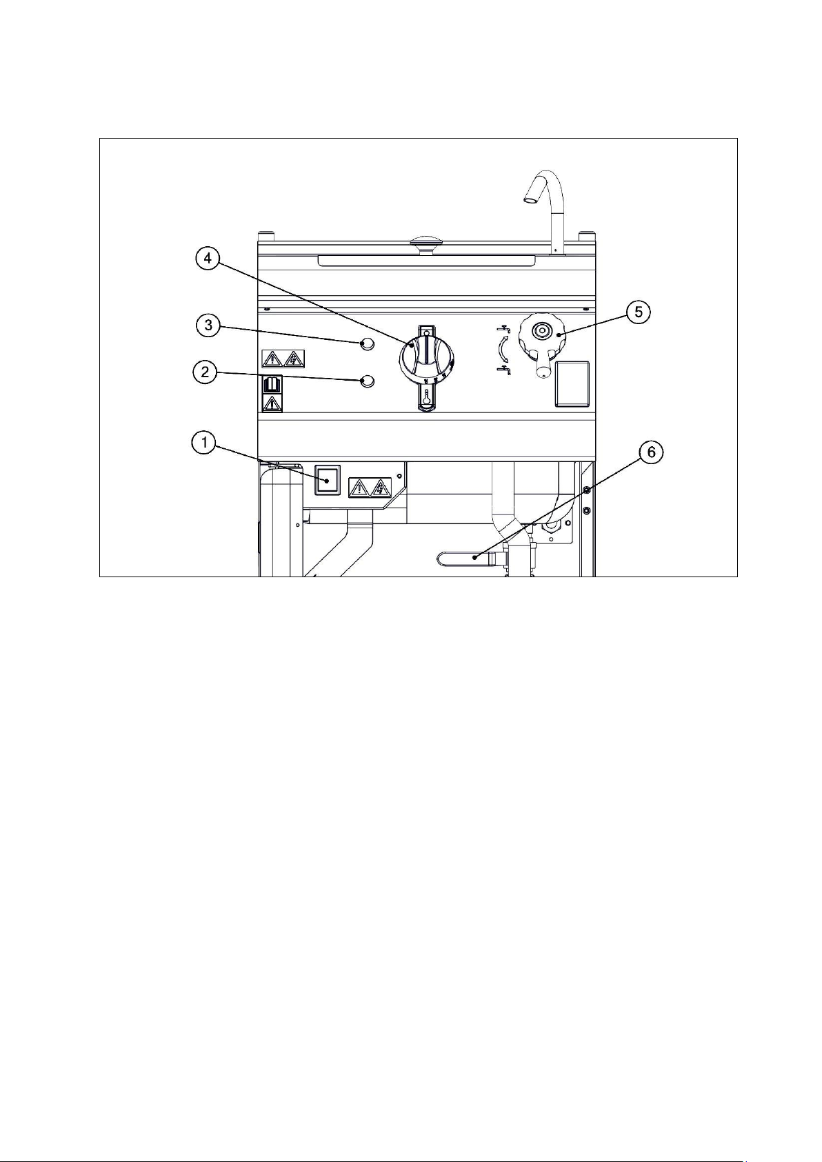
2.2 CONTROLS
1 -
ON/OFF SWITCH
4 -
TEMPERATURE CONTROL
2 -
POWER NEON (RED)
5 -
TAP
3 -
HEAT DEMAND NEON (AMBER)
6 -
DRAIN VALVE
4
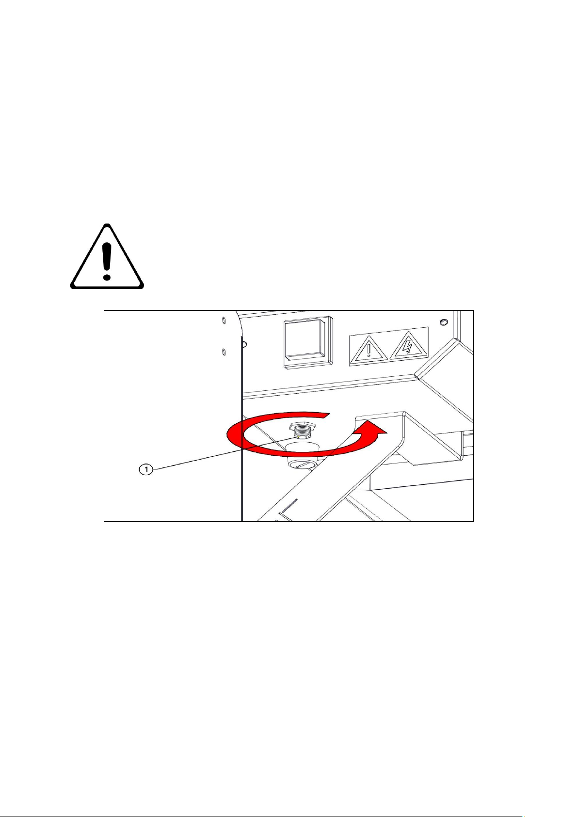
IF THE UNIT TURNS OFF, PRESS RESET BUTTON
2.3 USING THE APPLIANCE
2.3.1 Before use, clean the appliance inside and out. See section 3
2.3.2 Ensure drain valve is closed; fill with water to marked level.
2.3.3 Switch power on, 1.
2.3.4 Set temperature control 4 to desired setting.
2.3.5 To switch the unit off, turn temperature control 4 to `off` position.
5
 Loading...