

Page 1

T100944
Ref.11
F900 SERIES
User, installation and servicing instructions
HOTPLATE
COUNTERTOP AND
OVEN RANGE
E9042, E9084, E9184
Read these instructions before use
DATE PURCHASED:
MODEL NUMBER:
SERIAL NUMBER:
DEALER:
SERVICE PROVIDER:
1
Page 2

Dear Customer,
Thank you for choosing Falcon Foodservice Equipment.
This manual can be downloaded from www.falconfoodservice.com or scan
here.
IMPORTANT: Please keep this manual for future reference.
Falcon Foodservice Equipment
HEAD OFFICE
Wallace View, Hillfoots Road,
Stirling, FK9 5PY, Scotland
Tel: 01786 455200
PREVENTATIVE MAINTENANCE CONTRACT
To obtain maximum performance from this unit regular servicing of the appliance should be
undertaken to ensure correct operation, it is functioning as intended, and safe to use. We
recommend servicing in accordance with SFG20 Maintenance Schedules and as a
minimum, after 2,500 hours of use, or annually, whichever comes first and that a
maintenance contract be arranged with an appointed service contact. Visits may then be
made at agreed intervals to carry out adjustments and repairs.
WEEE Directive Registration No. WEE/DC0059TT/PRO
At end of appliance life, dispose of appliance and any replacement parts in a safe
manner, via a licensed waste handler. Appliances are designed to be dismantled
easily and recycling of all material is encouraged whenever practicable.
2
Page 3

SYMBOLS.
• SPANNER • SCREWDRIVER • COOKING OIL •GREASE
• SPARK IGNITION • FLAME • WARNING • VIEWPORT
• ALLEN KEY •IGNITER •C SPANNER
3
Page 4

These instructions are only valid if the country code appears on the
appliance. If the code does not appear on the appliance, refer to the technical
instructions for adapting the appliance to the conditions for use in that
country.
Installation must meet national or local regulations. Attention must be paid
to: safety (installation & use) regulations, health and safety at work act, local
and national building regulations, fire precautions act.
To prevent shocks, all appliances must be earthed.
This appliance has been UKCA/CE marked based on compliance with the
relevant Electrical and Electromagnetic Compatibility (EMC)
Regulations/Directives for the voltages stated on the data plate.
This equipment is for professional use only and must be used by qualified
persons.
The installer must instruct the responsible person(s) of the correct operation
and maintenance of the appliance.
Only competent persons are allowed to service this appliance.
Unless otherwise stated, parts which have been protected by the
manufacturer must not be adjusted by the installer.
Take care when moving an appliance fitted with castors.
The appliance must be serviced regularly by a qualified person. Service
intervals should be agreed with the service provider.
Check that no damage has occurred to the appliance, power cable, or plug
during transit. If damage has occurred, do not use this appliance.
Installation, periodic testing, repair and fixed wiring connections should
only be undertaken by a competent electrician.
Ensure power cable is routed free from the appliance to avoid damage.
We recommend supplementary electrical protection with the use of a type A
residual current device (RCD)
The appliance has been designed and approved to use Falcon Kick plates,
non Falcon kick plates could potentially adversely affect the performance of
the appliance by restricting the air to the appliance.
4
Page 5

CONTENTS
1.0 APPLIANCE INFORMATION ..................................................................................... 6
2.0 OPERATION .............................................................................................................. 7
2.0 COMPONENT PARTS ........................................................................................... 7
2.1 CONTROLS ............................................................................................................ 8
2.3 USING THE APPLIANCE ....................................................................................... 9
3.0 CLEANING AND MAINTENANCE .............................................................................10
4.0 SPECIFICATION .......................................................................................................12
5.0 DIMENSIONS / CONNECTION LOCATIONS ............................................................13
6.0 INSTALLATION .........................................................................................................14
6.1 SITING / CLEARANCES ...................................................................................... 15
6.2 ASSEMBLY ......................................................................................................... 15
6.3 COMMISSIONING ............................................................................................... 16
7.0 SERVICING ..............................................................................................................19
7.1 CONTROL PANEL REMOVAL ............................................................................ 19
7.2 OPERATING THERMOSTAT REMOVAL ............................................................ 19
7.3 SAFETY THERMOSTAT REMOVAL (E9184 Models Only) ................................ 20
7.4 HOTPLATE REMOVAL ........................................................................................ 21
7.5 TOP ELEMENT REMOVAL .................................................................................. 23
7.6 BOTTOM ELEMENT REMOVAL .......................................................................... 24
7.7 CIRCUIT DIAGRAM’S: ........................................................................................ 25
7.8 WIRING DIAGRAM’S: ......................................................................................... 28
8.0 OVEN DOOR REMOVAL ..........................................................................................32
9.0 ACCESSORIES ........................................................................................................33
10.0 FAULT FINDING .......................................................................................................33
11.0 SPARE PARTS .........................................................................................................33
12.0 SERVICE INFORMATION .........................................................................................34
5
Page 6

1.0 APPLIANCE INFORMATION
This appliance has been UKCA/CE marked based on compliance with the relevant
Electrical and Electromagnetic Compatibility (EMC) Regulations/Directives for the
voltages stated on the data plate.
A - Serial No
B - Model No
C - Flue Type
D - Gas Category
E - Gas Pressure
F - Gas Type
G - Gas Rate
H - Total Heat Input
I - Electrical Rating
J - Total Electrical Power
K - Magnetic Field Frequency
L - Electrical Phase Loading
6
Page 7

2.0 OPERATION
2.0 COMPONENT PARTS
A - Hotplate zone control
B - Oven zone control
C - Oven temperature control
D - Hotplate
E - Flue capper
F - Drip tray
G - Door
H - Shelf
7
Page 8

2.1 CONTROLS
A – Power neon (red)
B – Hotplate zone Indicator
C – Hotplate heat neon (amber)
D – Oven indicator
E – Oven temperature indicator
F – Oven heat neon (amber)
8
Page 9

2.3 USING THE APPLIANCE
2.1.1 Before use, clean the appliance hob. See section 3.
2.1.2 Switch hotplate control to required setting (A).
2.1.3 To switch off hotplates turn control knob to off position.
2.1.4 Switch oven zone control knob (B) to required setting.
2.1.5 Use temperature control knob (C) to adjust temperature…
Note: Slight variance in oven temperature may occur dependant on whether the
hotplates are on or off.
2.1.6 Caution: Opening the oven door will result in the escape of hot air. Care should be
taken to avoid being burned by such action.
2.1.7 To switch off oven turn knob (C) to off position.
9
Page 10
3.0 CLEANING AND MAINTENANCE
Before any cleaning is
undertaken, isolate the
appliance from the mains
power supply at the isolator
switch.
MAINTENANCE CHECK
Regular servicing of the appliance should be undertaken to ensure
correct operation, it is functioning as intended, and safe to use. We
recommend servicing after 2,500 hours of use, or annually,
whichever comes first.
Any maintenance schedule should be carried out in accordance
with SFG20 Maintenance Schedule. Should any issues with the
integrity of the components be identified these should be replaced.
If the appliance is not considered safe the unit should be removed
from service and the responsible person advised why the unit is not
safe to use and what remedial action is needed. Contents of the
maintenance schedule should be agreed with the maintenance
provider.
Failure to clean this appliance will
be detrimental to the performance
of the hotplate & oven.
3.1 HOB
3.1.1 At the end of each day or cooking period, turn off appliance and let it cool down.
3.1.2 Remove any trivet plates if used.
3.1.3 Clean the hob using soap and water ensuring that no food debris is left on the hob.
3.2 OVEN
3.2.1 Do not stand on oven door
3.2.2 Turn off and let oven cool down.
10
Page 11

3.2.3 Remove base tray, base plate and shelf hangers.
3.2.4 Clean oven chamber using soap and water.
3.2.5 Clean shelves and base tray using soap and water.
3.3 FLUE CAPPER
3.3.1 The flue capper can be removed for cleaning but must be replaced for use.
11
Page 12

4.0 SPECIFICATION
Live 1 ( Phase 1)
Brown
Live 2 ( Phase 2)
Black
Phase
Min Max
Actual (A)
E9042
E9084
E9184
Technical data for models are shown below:
This unit is suitable for AC supplies only.
The standard terminal arrangement is Three Phase 400V 3N~.
This appliance must be EARTHED.
Live 3 ( Phase 3) Grey
Neutral Blue
Earth Yellow/Green
Phase Min Max Actual (A)
L1 16.3 19.0 17.3
L2 16.3 19.0 17.3
L3 0 0 0
L1 32.5 38.0 34.6
L2 16.3 19.0 17.3
L3 16.3 19.0 17.3
Phase Min Max Actual (A)
L1 32.5 38.0 34.6
L2 32.5 38.0 34.6
L3 25.9 30.4 27.6
12
Page 13

5.0 DIMENSIONS / CONNECTION LOCATIONS
A = ELECTRICAL INLET
13
Page 14

6.0 INSTALLATION
ELECTRICAL SAFETY AND ADVICE REGARDING SUPPLEMENTARY ELECTRICAL
PROTECTION
Commercial kitchens and foodservice areas are environments where electrical appliances
may be located close to liquids, or operate in and around damp conditions or where restricted
movement for installation and service is evident.
The installation and periodic inspection of the appliance should only be undertaken by a
qualified, skilled and competent electrician; and connected to the correct power supply suitable
for the load as stipulated by the appliance data label.
The electrical installation and connections should meet the necessary requirements to the
local electrical wiring regulations and any electrical safety guidelines.
We recommend:-
Supplementary electrical protection with the use of a type A residual current device (RCD)
Fixed wiring appliances incorporate a locally situated switch disconnector to connect to,
which is easily accessible for switching off and safe isolation purposes. The switch
disconnector must meet the specification requirements of IEC 60947.
Your attention is drawn to:BS 7671:2018–Guidance Note 8 - 8.13 : Other locations of increased risk
It is recognized that there may be locations of increased risk of electric shock other than those
specifically addressed in Part 7 of BS 7671. Examples of such locations could include
laundries where there are washing and drying machines in close proximity and water is
present, and commercial kitchens with stainless steel units, where once again, water is
present.
Where because of the perception of additional risks being likely, the installation designer
decides that an installation or location warrants further protective measures, the options
available include:
Automatic Disconnection of Supply (ADS) by means of a residual current device having a
residual operating current not exceeding 30mA;
Supplementary protective equipotential bonding; and
Reduction of maximum fault clearance time.
14
Page 15
6.1 SITING / CLEARANCES
Where this appliance is to be positioned in close proximity to a wall,
partitions, kitchen furniture, decorative finishes, etc., it is recommended
that they be made of non-combustible material; if not, they shall be clad
with a suitable non-combustible heat insulating material, and that the
closest attention be paid to fire prevention regulations. If suiting, the
necessary clearances to any combustible wall must be the largest figure
given for individual appliance instructions.
When routing cable within the appliance ensure power cable is cable
tied to internal cable tray (On E9184 Version).
6.2 ASSEMBLY
6.2.1 Position appliance and level using feet or caster adjusters as shown below.
15
Page 16
6.3 COMMISSIONING
6.3.1 Remove rear hatch
6.3.2 Connect appliance to mains supply
6.3.3 Refer to section 2.3 or 2.4 for operation.
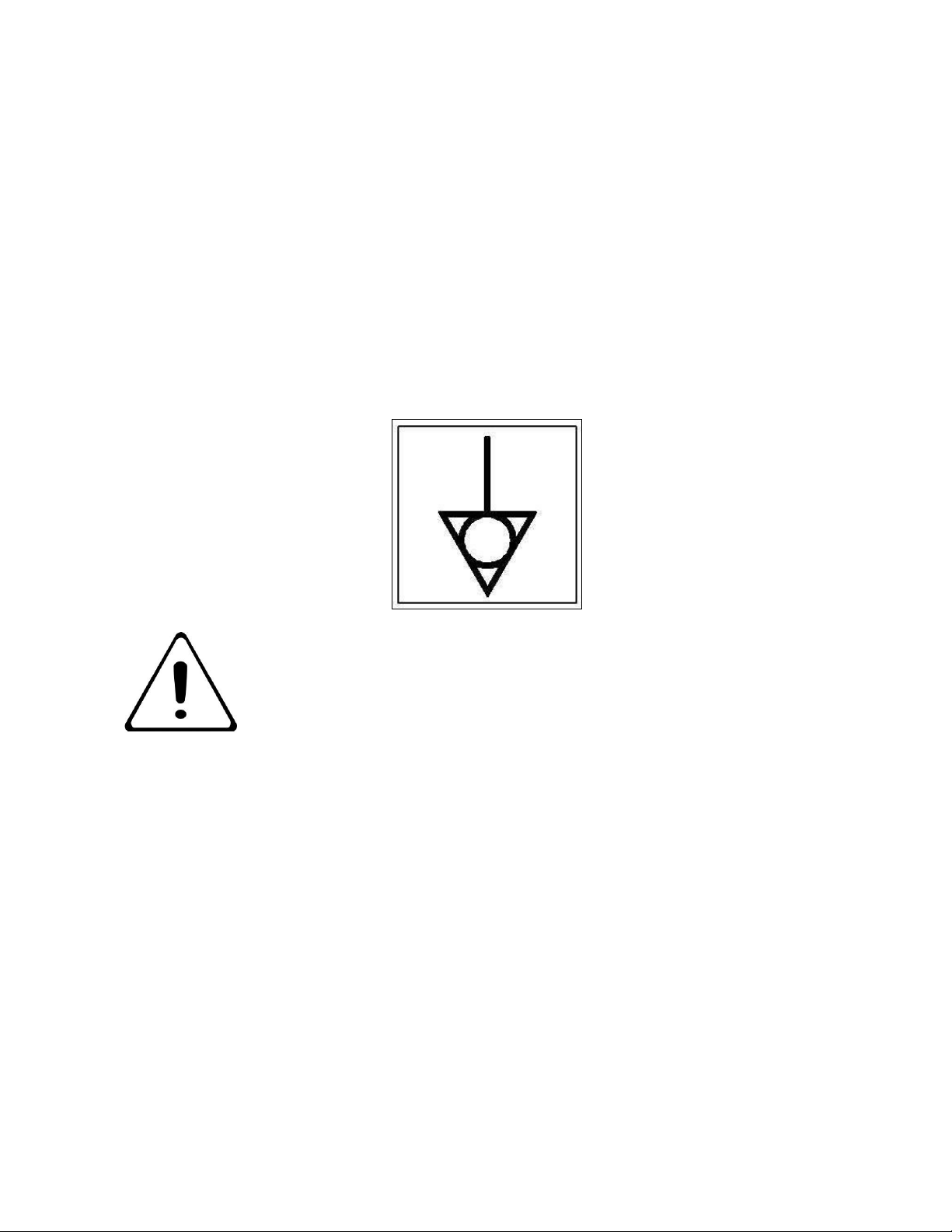
6.3.4 This appliance is also provided with a terminal for connection of an external
equipotential conductor. This terminal is an effective electrical contact with all fixed
exposed metal parts of the appliance, and shall allow the connection of conductor
having a nominal cross-section area of up to 10mm². It is located at the rear of the unit
and identified by the following label and must only be used for bonding purposes.
PLEASE FILL OUT THE INFORMATION TABLE ON THE FRONT COVER
AFTER COMMISSIONING.
6.4 SUITING “Patent No. GB 2540131”
6.4.1 Before leveling and suiting units ensure the units are fully built, including all
accessories and castings.
6.4.2 Undo the 4 fixing screws on the control panels and remove.
6.4.3 Remove the hob rear infill and replace with rear suiting plate and fixings.
6.4.4 Remove the front side panel countersunk screw and suiting plate.
16
Page 17

6.4.5 The DLS system is designed to give a quick and easy suiting solution. If you require
an improved seal between appliances we recommend you use, a food grade, high
temperature silicon sealant.
6.4.6 This can be supplied by Falcon Part No – 523400021
6.4.7 Apply a bead of silicon 5mm from profile edge as highlighted below.
6.4.8 Slide suited units into position.
17
Page 18

A
6.4.9 (A) Right hand unit: Screw the M5 x 40 screw (supplied in the kit) into one of the
suiting plates as shown and then insert through the front fixing holes of both units.
6.4.9 (B) Left hand unit: Slide the penny and lock washer on to the screw and secure using
the M5 nut.
6.4.10 (C) Remove the front bolts from feet, insert base tie plate and secure the bolts back
into position.
6.4.11 (D) Replace fixings on the rear hob and tighten screw caps into position.
D
B
6.4.12 Replace control panel as required.
C
18
Page 19

7.0 SERVICING
7.1 CONTROL PANEL REMOVAL
7.1.1 Remove as shown.
7.2 OPERATING THERMOSTAT REMOVAL
7.2.1 Remove operating thermostats as shown (only on E9184 model).
19
Page 20

7.3 SAFETY THERMOSTAT REMOVAL (E9184 Models Only)
BEFORE ATTEMPTING ANY MAINTENANCE, ISOLATE THE
APPLIANCE AT THE MAINS SWITCH AND TAKE STEPS TO
ENSURE THAT IT IS NOT INADVERTENTLY SWITCHED ON.
7.3.1
7.3.4
7.3.1 Undo screws on base access plate to enable thermostat assembly to drop out of
base.
7.3.2 Disconnect wires.
7.3.3 Undo screws on thermostat mounting plate.
7.3.4 Slide thermostat cover to provide access to safety thermostat.
7.3.5 Undo screws on base access plate to release thermostat from plate.
7.3.6 When re-fitting ensure all cable connections are restored as detailed in the wiring
diagram.
7.3.3
7.3.5
20
Page 21

7.4 HOTPLATE REMOVAL
A
7.4.1 Remove cover plates as required (only on E9184 model).
7.4.2 Undo hotplate centre fixing nut(s) and disconnect hotplate wiring at terminal bracket
(A) as appropriate.
21
Page 22

7.4.3 Lift-off hotplate as required.
7.4.4 When re-fitting hotplate, ensure seal has been fitted into groove of spill ring.
22
Page 23
7.4.5 Once the hotplate is sitting on the hob and the locating screw is through centre hole
in the hotplate support assembly, carefully align and centralise the hotplate. Refit the
centre fixing nut and re-tighten. This will pull down the hotplate centrally and equally.
Do not adjust the four corner screws that the hotplate sits on (these are only for
additional support and not for levelling).
7.5 TOP ELEMENT REMOVAL
7.5.1 Inside oven chamber, unscrew element fixing clips and loosen two bolts at rear of
element.
7.5.2 Disconnect from wiring and remove top element from oven.
23
Page 24

7.6 BOTTOM ELEMENT REMOVAL
7.6.1 Remove base shelves as required.
7.6.2 Remove screws from element fixing plate as required.
7.6.2 Disconnect wires and remove element from oven.
24
Page 25

7.7 CIRCUIT DIAGRAM’S:
25
Page 26

26
Page 27

27
Page 28
7.8 WIRING DIAGRAM’S:
28
Page 29
29
Page 30

30
Page 31

31
Page 32

8.0 OVEN DOOR REMOVAL
THE HINGE SPRING IS UNDER TENSION AND NO
ATTEMPT SHOULD BE MADE TO REMOVE THE PINS
WHEN THE DOOR IS OFF.
Turn off and let oven cool down.
Open the door fully and push an Ø4mm pin into the hole on each hinge.
Holding the door with both hands half way down each side, rotate and lift up until the hinge
hits the top of the hinge aperture.
Rotate hinge out of hinge aperture and lift door away
32
Page 33
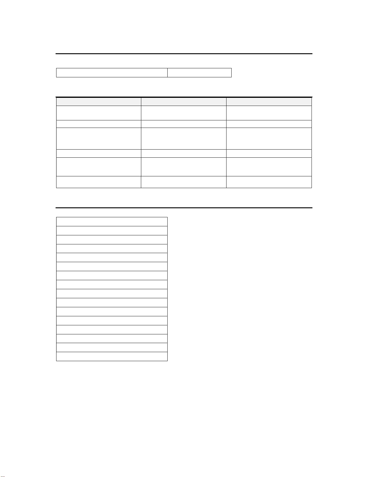
9.0 ACCESSORIES
Hotplate will not operate
Switch at off
p
osition
Change switch to position 1
Horizontal trivet plate 723410000
10.0 FAULT FINDING
FAULT
Unit will not turn ON No Power to unit Check power supply is
The oven will not operate The oven not switched on Check oven zone (element
The oven will not operate Safety stat tripped Call Engineer
Oven slow to heat Wrong element setting Check the element selector
Oven slow to heat Faulty Element Call Engineer
POSSIBLE CAUSES
REMEDY
connected & turned ON
selector) switch is on, and
turn oven temperature up
(oven zone) switch
11.0 SPARE PARTS
Oven top element
Oven bottom element
Hotplate 4.4kw
Hotplate seal
Control panel E9042
Control panel E9084
Control panel E9184
Power neon red
Heat demand neon amber
Hotplate control switch
Oven zone control switch
Oven thermostat switch
Safety thermostat
Hotplate control knob
Oven temperature control knob
Oven zone control knob
When ordering spares, quote the following:
Model Number
Serial number
Gas Type
This information is found on data plate on front panel. (See section 1.0)
Visit our website for further spares information.
33
Page 34

12.0 SERVICE INFORMATION
This unit carries an extensive mainland UK warranty. The warranty is in addition to and does
not change your statutory or legal rights.
The warranty policy can be found on our website which details the conditions of the warranty
and the exclusions.
https://www.falconfoodservice.com/info-centre/policy
Service calls to equipment under warranty will be carried out in accordance with the
conditions of sale.
Warranty calls can be made between 8:30 am and 5:00 pm weekdays only.
To ensure your warranty enquiry is handled as efficiently as possible, ensure you have the
following appliance information prior to calling us:
1. Model number – found on data plate
2. Serial number – found on data plate
3. Brief description of the issue
To contact Falcon for a warranty issue dial (UK only) 01786 455 200 and select Warranty
Issues from the menu.
34
 Loading...