

Falcon E7204, E7211, E7208/2, E7211 Rack, E7211 Trolley Installation And Servicing Instructions
...Page 1
E7204, E7208 and E7211
Forced Convection Ovens
CAUTION: Read the instructions before
using the appliance.
INSTALLATION and SERVICING
INSTRUCTIONS
IMPORTANT
The installer must ensure that the installation of the appliance is in conformity with these
instructions and National Regulations in force at the time of installation. Particular attention
MUST be paid to –
BS7671 IEE Wiring Regulations
Electricity at Work Regulations
Health And Safety At Work Act
Fire Precautions Act
This appliance has been CE-marked on the basis of compliance with the Low Voltage and EMC
Directives for the voltages stated on the Data Plate
WARNING -THIS APPLIANCE MUST BE EARTHED
On completion of the installation these instructions should be left with the Engineer-in-Charge for
reference during servicing. Further to this, The Users Instructions should be handed over to the
User, having had a demonstration of the operation and cleaning of the appliance.
IT IS MOST IMPORTANT THAT THESE INSTRUCTIONS BE CONSULTED BEFORE
INSTALLING AND COMMISSIONING THIS APPLIANCE. FAILURE TO COMPLY WITH THE
SPECIFIED PROCEDURES MAY RESULT IN DAMAGE OR THE NEED FOR A SERVICE
CALL.
PREVENTATIVE MAINTENANCE CONTRACT
In order to obtain maximum performance from this unit we would recommend that a Maintenance
Contract be arranged with SERVICELINE. Visits may then be made at agreed intervals to carry
out adjustments and repairs. A quotation will be given upon request to the contact numbers
below.
WEEE Directive Registration No. WEE/DC0059TT/PRO
At end of unit life, dispose of appliance and any replacement parts in a safe
manner, via a licensed waste handler.
Units are designed to be dismantled easily and recycling of all material is
encouraged whenever practicable.
Falcon Foodservice Equipment
Head Office and Works
Wallace View, Hillfoots Road, Stirling. FK9 5PY. Scotland.
ServicelinePHONE : 01438 363 000
Warranty Policy Shortlist
Warranty does not cover :Correcting faults caused by incorrect installation of a product.
Where an engineer cannot gain access to a site or a product.
T100683 Ref.5
Page 2

Repeat commission visits.
Replacement of any parts where damage has been caused by misuse.
Engineer waiting time will be chargeable.
Routine maintenance and cleaning.
Gas conversions i.e. Natural to Propane gas.
Descaling of water products and cleaning of water sensors where softeners/conditioners are not
fitted, or are fitted and not maintained.
Blocked drains.
Independent steam generation systems.
Gas, water and electrical supply external to unit.
Light bulbs.
Re-installing vacuum in kettle jackets.
Replacement of grill burner ceramics when damage has been clearly caused by misuse.
Where an engineer finds no fault with a product that has been reported faulty.
Re-setting or adjustment of thermostats when unit is operating to specification.
Cleaning and unblocking of fryer filter systems due to customer misuse.
Lubrication and adjustment of door catches.
Cleaning and Maintenance:
Cleaning of burner jets
Poor combustion caused by lack of cleaning
Lubrication of moving parts
Lubrication of gas cocks
Cleaning/adjustment of pilots
Correction of gas pressure to appliance
Renewing of electric cable ends
Replacement of fuses
Corrosion caused by use of chemical cleaners.
Electrical Safety and Advice Regarding Supplementary Electrical Protection
Commercial kitchens and foodservice areas are environments where electrical appliances may be located
close to liquids, or operate in and around damp conditions, or where restricted movement for installation
and service is evident.
The installation and periodic inspection of the appliance should only be undertaken by a qualified, skilled
and competent electrician; and connected to the correct power supply suitable for load as stipulated by the
appliance data label.
The electrical installation and connections should meet the necessary requirements to local electrical
wiring regulations and electrical safety guidelines.
We recommend:-
Supplementary electrical protection with use of a residual current device (RCD).
Fixed wiring appliances incorporate a locally situated switch disconnector to connect to, which is
easily accessible for switching off and safe isolation purposes. The switch disconnector must meet
the specification requirements of IEC 60947.
Page 3
SECTION 1 – INSTALLATION
UNLESS OTHERWISE STATED, PARTS WHICH HAVE BEEN PROTECTED BY THE
MANUFACTURER ARE NOT TO BE ADJUSTED BY THE INSTALLER
1.1 MODEL NUMBER, NETT WEIGHTS and DIMENSIONS
MODEL
WIDTH mm
DEPTH mm
HEIGHT mm
WEIGHT kg
E7204
860
1015
1470
170
E7208
1000
1070
1525
220
E7208/2
1000
1070
1910
420
E7211
1000
1070
1525
270
E7211 Trolley
820
740
910
32
E7211 Rack
680
560
830
37
1.2 SITING
The oven must be situated on a reasonably level surface. The unit feet are adjustable to
facilitate levelling however, the adjustment range is limited.
Installation must be executed in accordance with local and/or national regulations listed on
the cover of this manual. A competent installer must be employed.
1.2.1 Installing Clearances
A clearance of at least 150mm must be allowed from any combustible wall. Clearance must
also be allowed at the rear from any non-combustible wall to let cooling air into the rear fan.
If practicable, it is recommended that a clearance of at least 400mm be allowed from any
side wall. This will provide access for adjustment of the rear levelling bolts and to effect
removal of the RH side panel to facilitate servicing. If the unit is being installed as part of a
suite, it is further recommended that it be positioned at the RH end to provide unrestricted
access for servicing of controls etc.
If the unit is to be installed in a suite, either centrally or adjacent to a wall with a 'boxed in'
void at the rear, it is important that the void be adequately ventilated. This will ensure a
supply of air to the motor cooling fan at the rear of the oven.
1.3 ELECTRICAL SUPPLY
This unit is suitable for AC supplies only. The standard terminal arrangement is for 3 phase,
4 wire connection, but by linking the 3 line terminals, the unit can be connected to a single
phase supply.
The cable entry is at the bottom RH rear of the unit via a 32mm dia conduit. Access to the
terminals is gained by removing the RH side panel.
A suitably rated isolating switch with a minimum 3mm contact separation in all poles must be
installed and the wiring executed in accordance with the relevant regulations listed on the
front cover of this manual.
Warning
The appliance must be earthed. (An earth terminal is provided).
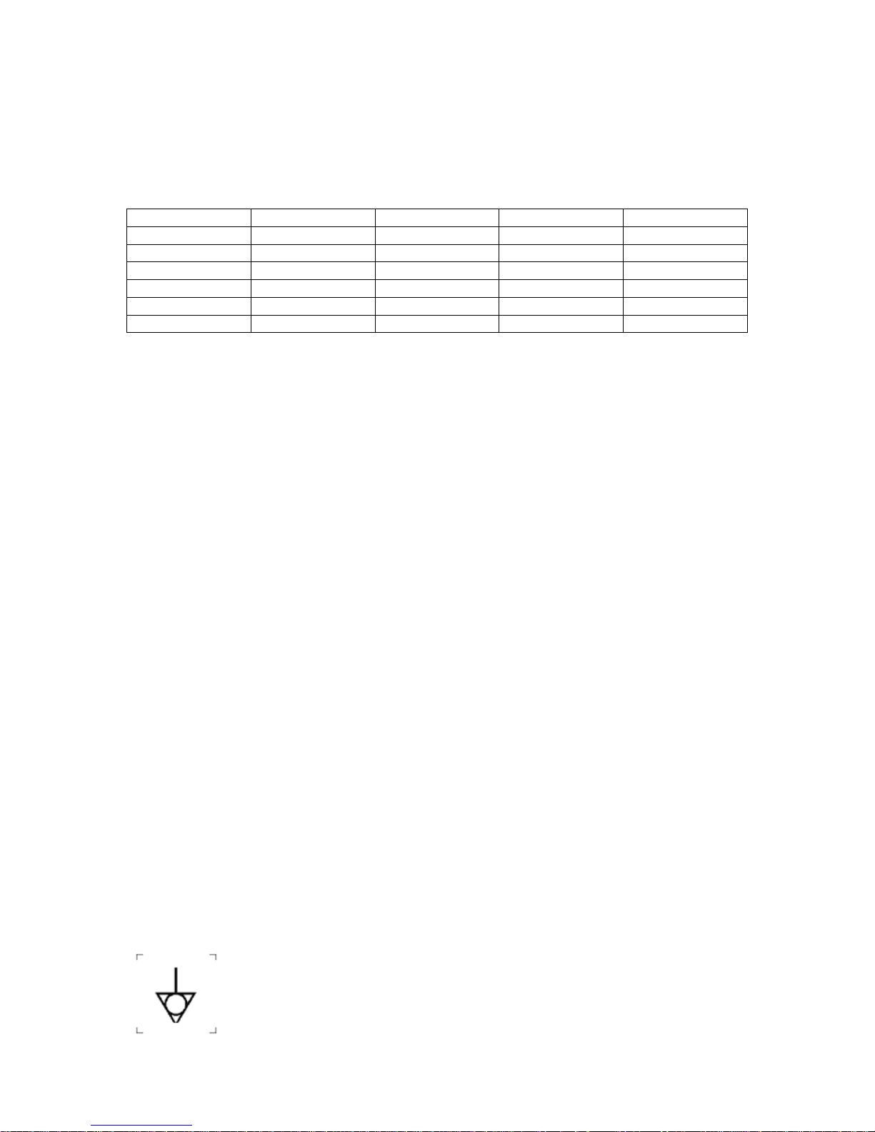
The appliance is also provided with a terminal for the connection of an
external equipotential conductor. This terminal is in effective electrical contact
with all fixed exposed metal parts of the appliance, and shall allow the
connection of a conductor having a nominal cross-sectional area of up to 10
mm². It is located on the rear panel and is identified by the following label and
must only be used for bonding purposes.
Page 4
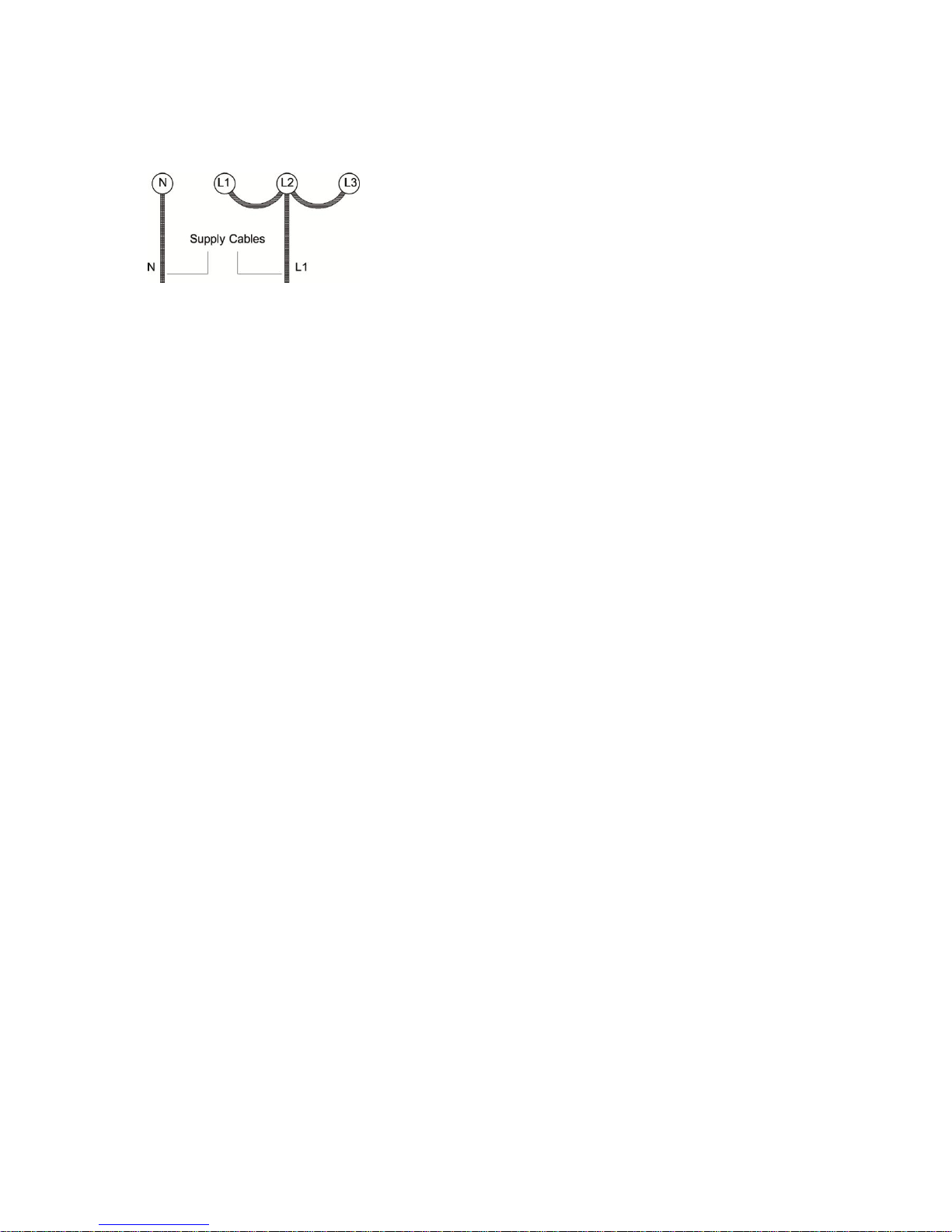
Note
When connecting to a single phase supply, the three line terminals must be connected
together using the wire links provided. It is important that the links and incoming supply cable
are connected exactly as shown in the following diagram.
1.4 ELECTRICAL RATING
The electrical loadings are as stated on the appliance data plate.
1.5 FAN UNIT
This is a unit specially developed for use in forced convection ovens. It has two fans directly
mounted on the motor shaft. The larger fan is inside the oven, the purpose being to circulate
air around the cooking space whilst the smaller externally mounted fan serves to cool the
motor.
1.6 INSTRUCTION TO USER
Hand the USER'S INSTRUCTIONS to the user or purchaser and ensure that the instructions
for the correct use and cleaning are properly understood.
The location of the electrical supply switch should be made known to the user for use in an
emergency or during cleaning.
SECTION 2 - ASSEMBLY and COMMISSIONING
Warning
Due to the appliance weight (see Section 1.1), it is recommended that when lifted manually,
that it be supported by 4 people (one at each corner).
Important
Care must be taken when lifting heavy loads and ensure that correct lifting techniques are
employed. For reference see the HSE publication, Manual Handling of Loads Regulations.
2.1 ASSEMBLY
2.1.1 Oven without Stand
a) Unpack unit and remove all loose components from oven compartment.
b) Manoeuvre oven to required position and level using the adjustable feet. Also, refer to
Section 2.1.3 if applicable.
c) Connect electricity supply.
d) Insert the shelves within the oven.
Note
Feet can be secured to floor using holes provided.
2.1.2 Oven with Stand
a) Unpack unit and stand. Remove all loose components from oven compartment.
b) Ensure the leg securing bolts are turned fully back.
c) Lift oven on to stand. If a stand is fitted with castors, these should be locked.
d) Tighten leg stand securing bolts.
e) Manoeuvre unit into position.
f) For stand on castors, fit securing chain to prevent straining the electrical cable.
Page 5

g) For fixed stand, level using the adjustable feet. Also, refer to Section 2.1.3 if applicable.
Note
Feet can be secured to floor using holes provided.
2.1.3 Oven with Trolley
a) Unpack oven, trolley and rack assembly as detailed in Section 2.1.2, items a) to d).
b) Manoeuvre unit into required location and level by turning adjustable feet as required.
Feet should also be used to line up unit base with trolley tray.
c) Connect to electricity supply.
Note
Feet can be fixed to floor using holes provided in feet.
2.2 COMMISSIONING THE APPLIANCE
These units have two mode switches.
For controls refer to users instruction fig 1
Fan Mode Switch: Heat up/cool down.
In the heat-up mode, the required Cook Mode must be selected: Cook only/Cook & Hold.
The ovens are fitted with a bi-directional fan controlled by a PLC (programmable logic
controller). The fan timings are:
For heat-up mode (door closed):
Operation
Duration (seconds)
OFF (start up)
12
then repeat loop:
Anti-clockwise
120
OFF
12
Clockwise
120
OFF
12
For cool down mode (door open):
OFF (start up)
5
Anti-clockwise
continuous
The on/off knob is fitted on thermostat spindle.
Turn knob clockwise to switch fan and elements on.
Turn knob fully anti-clockwise to switch off.
2.2.1 Basic Checks
a) Ensure all packing material has been removed. If unit is fitted with shelf runners, ensure
oven grid shelves slide in and out properly.
b) Switch on main supply, red neon should light.
c) With doors open and switch set to Cool Down, turn thermostat knob clockwise to switch
fan on.
d) Check fan rotates anti-clockwise.
E7204/E7208 models only
e) Push oven light switch to observe oven light(s) operate.
2.2.2 System Operational Checks
Select Cook Only Mode (Timer set to 'MAN')
a) Set thermostat to 200oC. Heat Required neon (Amber) should illuminate.
Page 6

b) Allow oven to heat up. Amber neon will go out when desired temperature is reached.
Check that centre oven temperature corresponds to setting. The temperature will cycle
around set point and the thermostat will switch the elements on and off to maintain setting.
c) Check fan stops when doors are opened, this should also cut power to elements. Amber
neon will stay lit if temperature is below desired setting.
d) Check fan rotates with doors open or closed when the fan switch is pressed to cool down
mode.
e) Return to heat-up mode to check timer operation. This should switch off the elements and
sound a buzzer at the end of a pre-set time interval. Turn timer knob to 'MAN' setting and
observe that cook thermostat is activated and buzzer stops.
Select the Cook & Hold Mode (Mode switch neon should illuminate).
a) Check timer operates as required. Cook thermostat should operate until timer zeros.
When this occurs, operation should switch to Hold thermostat.
b) With oven remaining in this mode, check centre oven temperature settles to 80oC. (+/5oC).
SECTION 3 - SERVICING
Warning
BEFORE CARRYING OUT ANY MAINTENANCE ON THIS APPLIANCE ENSURE THE
UNIT ELECTRICITY SUPPLY IS ISOLATED.
Controls are removed as follows:
Note
When replacing wiring connections, refer to wiring diagram contained in this manual from
which it can be seen that all wires are numbered.
3.1 CONTROL PANEL
a) Undo fixings at top of panel.
b) Pull hinged panel forward.
3.2 RH SIDE PANEL
a) Open control panel.
b) Undo front edge fixings.
c) Pull panel sideways at front and push back to clear rear catches.
3.3 LH SIDE PANEL
a) Open oven doors.
b) Undo front edge fixings.
c) Pull panel sideways at front and push back to clear rear catches.
3.4 OUTER BACK PANEL
Undo fixings along perimeter and remove panel.
3.5 LOWER FRONT COVER PANEL
a) Undo fixings along lower edge.
b) Open oven doors and undo fixings along top.
c) Pull panel off.
3.6 DIN RAIL MOUNTED RELAYS
a) Remove RH side panel as detailed in Section 3.2.
b) Remove electrical terminals.
c) Pull relay away from base to replace it.
d) To replace relay base, unclip from din rail by levering lower edge catch downward.
e) Replace in reverse order.
3.7 PLC, CONTACTORS and CONNECTOR BLOCKS
a) Remove side panel.
Page 7

b) Remove electrical connections, noting positions.
c) Unclip component by levering lower edge catch downward.
d) Replace in reverse order.
3.8 COOK THERMOSTAT
a) Open control panel as detailed in Section 3.1.
b) Disconnect electrical leads.
c) Remove knob and undo fixings which secure thermostat to panel.
d) Undo capillary tube securing clip fixing.
e) Undo phial and bracket fixings from inside oven chamber.
f) Ease phial through hole in oven side panel.
g) Replace in reverse order.
3.9 HOLD THERMOSTAT
a) Remove side panel as detailed in Section 3.2.
b) It is possible to adjust hold thermostat temperature between 75 and 85oC by means of the
spindle.
To Remove:
c) Disconnect electrical leads.
d) Undo fixings which secure thermostat to inner control panel.
3.10 TIMER
a) Open control panel as detailed in Section 3.1.
b) Remove knob and undo fixings securing timer to panel.
c) Disconnect electrical leads.
d) Replace in reverse order.
3.11 BUZZER, INPUT MAINS FILTER and START/RUN RELAY
a) Remove side panel as detailed in Section 3.2.
b) Disconnect electrical leads.
c) Remove fixing which secures component to inner control panel.
d) Replace in reverse order.
3.12 INDICATOR LAMPS and SWITCHES
a) Open control panel as detailed in Section 3.1.
b) Disconnect leads from part being replaced.
c) Push component from location.
d) Replace in reverse order.
3.13 DOOR SWITCH
a) Remove bottom front panel. (See Section 3.5)
b) Undo fixings to remove switch from support bracket.
c) Disconnect electrical leads.
d) Replace in reverse order.
3.14 MOTOR UNIT
Remove unit from inside compartment as follows:
a) Remove shelves and hangers.
b) Remove fixings and withdraw fan baffle.
c) Remove fixing bolt from shaft.
d) Using a taper puller, remove fan impellor.
e) Remove fixings which secure motor to oven rear panel. Pull unit forward and rest upon
oven base.
f) Remove motor terminal wires, noting locations and withdraw assembly from chamber.
g) Remove motor by undoing fixings (one per leg in 'spider' mounting).
h) Fit replacement motor in reverse order.
Note
Page 8

Oven baffle is not symmetrical, fixings have been offset to ensure correct relocation.
3.15 OVEN LAMPS
To Replace Bulb
a) Undo lens cover fixings.
b) Undo bulb and replace.
c) Refit lens cover and ensure seal is not damaged.
To Replace Assembly
a) Remove LH outer side panel. (See Section 3.3)
b) Disconnect electrical connections.
c) Undo lens cover fixings.
d) Unclip housing from aperture.
Replace in reverse order.
3.16 CAPACITOR
a) Remove side panel.
b) Disconnect two capacitor leads at terminal block.
c) Undo fixing on capacitor base and remove unit.
d) Replace in reverse order.
3.17 ELEMENTS
a) Remove oven shelves and hangers.
b) Remove fixings and withdraw fan baffle.
c) Remove element plate and spacer bracket fixings. Pull elements forward until all
terminals are inside oven. This will also bring oven safety thermostat mounting plate forward.
d) Remove terminals taking care that wire end remains inside oven.
e) Remove element fixing screws.
f) Replace in reverse order. Take care to ensure that safety thermostat bracket is correctly
positioned.
Note
Oven baffle is not symmetrical, fixings have been offset to ensure correct relocation.
3.18 OVEN SAFETY THERMOSTAT
a) Safety thermostat can be reset by means of a thin tool under control compartment on
Right Hand side Section 3.1 & 3.2 above.
b) Press inset button on safety thermostat with thin tool to reset.
Warning
If safety thermostat has been activated and requires to be reset, this could be an indication
that additional parts are faulty.
c) To remove safety thermostat, access can be gained by removing side panel as detailed in
Section 3.1 & 3.2 above, disconnect electrical leads and undo safety stat fixing nut under
base.
d) Replace in reverse order.
3.19 OVEN DOOR SEAL REPLACEMENT
Seal is fitted to front frame using countersunk screws.
When fitting new seal, place metal strip in position, pierce holes in seal and secure to holes
in front frame.
3.20 DOOR REMOVAL
a) Remove bottom front panel. (See Section 3.5)
b) Open doors through 90 degrees and remove fixings which secure door to bottom door
bracket.
Page 9

c) Lift door up slightly, ease sideways to clear bottom bracket and withdraw from top hinge
pin.
3.21 DOOR LINKAGE SPROCKET
a) Remove door. (See Section 3.20)
b) Slacken turnbuckles to allow chain to be slipped from sprocket.
c) Push out roll pin which holds sprocket upon lower hinge pin. Push out roll pin holding
door switch cam if RH sprocket is being removed.
d) Pull up lower hinge pin and remove sprocket.
e) Replace in reverse order. Refer to door linkage adjustment section for alignment and
tensioning of components.
3.22 DOOR LINKAGE CHAIN and ROD
a) Remove bottom front panel. (See Section 3.5)
b) Slacken turnbuckle to remove tension from chains.
c) Remove spring clip from link which joins chain to turnbuckle. Push out joining link and
withdraw chain rod assembly.
d) Replace in reverse order, referring to door linkage adjustment section, door linkage
alignment section and Figures 2 and 3.
3.23 DOOR LINKAGE ADJUSTMENT and TENSIONING
Due to operational stretching of components or removal for maintenance, occasions will
arise when the door linkage mechanism will require adjustment.
The method to use is as follows:-
Push door handle until RH door makes contact with seal. The LH door should now be 12 to
15mm proud of the RH door at vertical join.(see Figure 2) If LH door is less than this
dimension, slacken both turnbuckle locknuts and rotate LH turnbuckle toward chain and the
right turnbuckle away from chain by the same amount.
Repeat procedure until desired dimension is achieved. If LH door is greater than desired
setting then above procedure should be carried out in reverse.
After doors are synchronised, the linkage should be put under tension by slightly twisting the
turnbuckles toward one other by the same small amount.
The tension should be such that no free play is available between chains and their
sprockets.
Page 10

3.24 DOOR LINKAGE ALIGNMENT
When linkage components have been disturbed during repair, the initial coarse assembly,
alignment will be achieved by positioning the chains on their sprockets as indicated in Figure
3. Doors should be in the closed position when carrying out this task.
3.25 DOOR CATCH MECHANISM
a) Open doors and remove front and rear fixings which secure top panel. Withdraw top panel
by lifting at rear to clear flue outlet cover and slide it forward. Twist rear slightly to one side to
clear locating angles at top panel front sides.
b) Unhook spring and remove nut and split pins from top of toggle plate pins.
c) Replace new component(s). Take care to re-assemble in correct order.
d) Replace top panel.
3.26 DOOR WINDOW (E7204 & E7208 ONLY)
a) Remove door as described in Section 3.20.
b) Remove all top and bottom door flange fixings plus those that secure sealing strip to side
flange.
c) Lay door down on outer surface and prise out inner lining. Window assembly may now be
removed.
d) When only replacing one single glass panel, dismantle frame by removing all fixings
around window assembly periphery.
e) Replace glass and sealing strip if necessary. Carefully re-assemble window structure.
f) Re-fit all door components in reverse order.
SECTION 4 – SPARES
Page 11

When ordering spares, please quote Model number, serial number and voltage as stated on
data plate.
Element Outer 732920019
Element Inner 732920018
Terminal Block White Nylon 531740420
Thermostat Cook 731910500
Thermostat Hold 732920055
Thermostat Oven Safety Klixon 535420015
Thermostat Oven Safety EGO 732920130
Buzzer White 535500035
Buzzer Black 734510130
Cooling Fan 735400360
Door Seal E7204 531930526
Door Seal E7208 532930043
Door Seal E7211 531940099
Neon Red 730962010
Neon Amber 730962040
Cool/Heat Switch 732920047
Cook/Hold Switch 732920051
Fan Switch 732910481
Timer c/w Knob 732910495
Oven Light Switch 535500037
Control Knob 732920048
Oven Fan 732920008
Fuse 8A 732920068
P.L.C Controller 732920059
Contactor MC22B 731350070
Relay-Fan 732920062
Relay Single Pole 535770128
Realy Start/Run 732920066
Terminal Block Assembly 732920069
Filter Suppression 732920096
Microswitch Door 531925260
Oven Lamp Assy 732910390
Oven Lamp 732910350
Page 12

Page 13

 Loading...