

Page 1
F900 SERIES
User, installation and servicing instructions
RISE and FALL GRILL
E600
Read these instructions before use
T100913
REV. 9
DATE PURCHASED:
MODEL NUMBER:
SERIAL NUMBER:
DEALER:
SERVICE PROVIDER:
Page 2
Falcon Foodservice Equipment
HEAD OFFICE
Wallace View, Hillfoots Road, Stirling, FK9 5PY, Scotland
PREVENTATIVE MAINTENANCE CONTRACT
To obtain maximum performance from this unit regular servicing of the appliance should be undertaken to
ensure correct operation, it is functioning as intended, and safe to use. We recommend servicing in
accordance with SFG20 Maintenance Schedules and as a minimum, after 2,500 hours of use, or annually,
whichever comes first and that a maintenance contract be arranged with an appointed service contact.
Visits may then be made at agreed intervals to carry out adjustments and repairs.
WEEE Directive Registration No. WEE/DC0059TT/PRO
At end of appliance life, dispose of appliance and any replacement parts in a safe manner, via a
licensed waste handler. Appliances are designed to be dismantled easily and recycling of all
material is encouraged whenever practicable.
Dear Customer,
Thank you for choosing Falcon Foodservice Equipment.
This manual can be downloaded from www.falconfoodservice.com or scan
here.
IMPORTANT: Please keep this manual for future reference.
Page 3

SYMBOLS
SCREWDRIVER
SPANNER
COOKING OIL
GREASE
WARNING
SPARK IGNITION
FLAME
VIEWPORT
ALLEN KEY
IGNITER
C SPANNER
REMOVE DEVICE
PLUG REMOVER
Page 4

• These instructions are only valid if the country code appears on the appliance. If the
code does not appear on the appliance, refer to the technical instructions for adapting
the appliance to the conditions for use in that country.
• Installation must meet national or local regulations. Attention must be paid to: gas
safety (installation & use) regulations, health and safety at work act, local and national
building regulations, fire precautions act.
• To prevent shocks, all appliances must be earthed.
• This appliance has been CE-marked on the basis of compliance with the Low Voltage
and EMC Directives for the voltages stated on the data plate.
• This equipment is for professional use only and must be used by qualified persons.
• The installer must instruct the responsible person(s) of the correct operation and
maintenance of the appliance.
• Only competent persons are allowed to service or convert the appliance to another gas
type.
• Gas appliances must have a stop cock fitted in the supply pipe work. The user must be
familiar with the location and operation of this device in order to turn off the supply of
gas in the event of an emergency.
• Unless otherwise stated, parts which have been protected by the manufacturer must
not be adjusted by the installer.
• Take care when moving an appliance fitted with castors.
• The appliance must be serviced regularly by a qualified person. Service intervals should
be agreed with the service provider.
• Check that no damage has occurred to the appliance, power cable, or plug during
transit. If damage has occurred, do not use this appliance.
Page 5

• Installation, periodic testing, repair and fixed wiring connections should only be
undertaken by a competent electrician.
• Ensure power cable is routed free from the appliance to avoid damage.
• We recommend supplementary electrical protection with the use of a type A residual
current device (RCD)
• The appliance has been designed and approved to use Falcon kick plates, non Falcon
kick plates could potentially adversely affect the performance of the appliance by
restricting the air to the appliance.
IMPORTANT INSTALLATION INFORMATION
ELECTRICAL SAFETY AND ADVICE REGARDING SUPPLEMENTARY ELECTRICAL
PROTECTION
Commercial kitchens and foodservice areas are environments where electrical appliances may be located
close to liquids, or operate in and around damp conditions or where restricted movement for installation and
service is evident.
The installation and periodic inspection of the appliance should only be undertaken by a qualified, skilled
and competent electrician; and connected to the correct power supply suitable for the load as stipulated by
the appliance data label.
The electrical installation and connections should meet the necessary requirements to the local electrical
wiring regulations and any electrical safety guidelines.
We recommend:-
• Supplementary electrical protection with the use of a type A residual current device (RCD)
• Fixed wiring appliances incorporate a locally situated switch disconnector to connect to, which is easily
accessible for switching off and safe isolation purposes. The switch disconnector must meet the
specification requirements of IEC 60947.
Your attention is drawn to:BS 7671:2018–Guidance Note 8 - 8.13 : Other locations of increased risk
It is recognized that there may be locations of increased risk of electric shock other than those specifically
addressed in Part 7 of BS 7671. Examples of such locations could include laundries where there are
washing and drying machines in close proximity and water is present, and commercial kitchens with
stainless steel units, where once again, water is present.
Where because of the perception of additional risks being likely, the installation designer decides that an
installation or location warrants further protective measures, the options available include:
• Automatic Disconnection of Supply (ADS) by means of a residual current device having a residual
operating current not exceeding 30mA;
• Supplementary protective equipotential bonding; and
• Reduction of maximum fault clearance time.
The provision of RCDs and supplementary bonding must be specified by the host organization’s appointed
installation designer or electrical contractor and installed by a suitably qualified and competent electrician
so as to comply with Regulations 419.2 and 544.2
Page 6

THE MANUFACTURER DECLINES ALL RESPONSIBILITY FOR DAMAGE DUE TO
INCORRECT INSTALLATION, TAMPERING, IMPROPER USE, FAULTY MAINTENANCE,
FAILURE TO OBSERVE THE CURRENT REGULATIONS AND INCOMPETENCE.
THE MANUFACTURER RESERVES THE RIGHT TO MODIFY WITHOUT NOTICE THE
APPLIANCE CHARACTERISTICS DESCRIBED IN THIS HANDBOOK.
Training and competence
To help ensure the safe use of this appliance there is a requirement for you to provide
whatever information, instruction, training and supervision as is necessary to ensure, so
far as is reasonably practicable, the health and safety of all users.
For further help and information on training and competence we would refer you the
Health and Safety Executive website; www.hse.gov.uk document ref: health and safety
training INDG345. International customers should default to the health and safety
guidelines provided by your government body.
Risk assessment
As part of managing the health and safety of your business you must control any risks
identified in your commercial kitchen. To do this you need to think about what might
cause harm to people and decide whether you are taking reasonable steps to prevent
that harm. This is known as risk assessment. It is important to consider the environment
around the product as well as the product itself. For example oil or food spills will
present a significant risk so users so the need to immediately clean up such spills must
be reflected in staff training.
For further help and information on risk assessments we would refer you to
you the Health and Safety Executive website; www.hse.gov.uk document ref:
risk assessment INDG163. International customers should default to the
health and safety guidelines provided by your government body.
Page 7

CONTENTS
1. INSTALLATION
1.1 IMPORTANT INFORMATION
1.2 POSITIONING
1.3 CONNECTING TO THE MAINS
2. INSTRUCTIONS FOR E600
2.1 FUNCTIONING
2.2 SETTING
2.3 USER INTERFACE
2.4 MANUAL MODE
3. CLEANING AND MAINTENANCE
3.1 ROUTINE MAINTENANCE
Page 8
SECTION 1 INSTALLATION
1.1 IMPORTANT INFORMATION
Read this handbook through carefully as it provides important information about safely
installing, using and servicing the unit. Keep the handbook in a safe place for future reference
by the various operators.
· The unit must be installed by professionally qualified personnel in accordance with the
manufacturer’s instructions.
· The unit must be used only by people who have been trained to use it.
· Do not leave the unit unattended during use.
· Turn the unit off in the event of a failure or malfunction. Repairs should only be carried out
by an authorised repair centre using original parts.
· Failure to do so could compromise unit safety.
The unit conforms to the following standards:
- Low voltage directive 2006/95/EC;
- E.M.C. directive 2004/108/EC concerning electromagnetic compatibility;
1.2 POSITIONING
Remove the unit from the packaging and make sure it is in perfect condition.
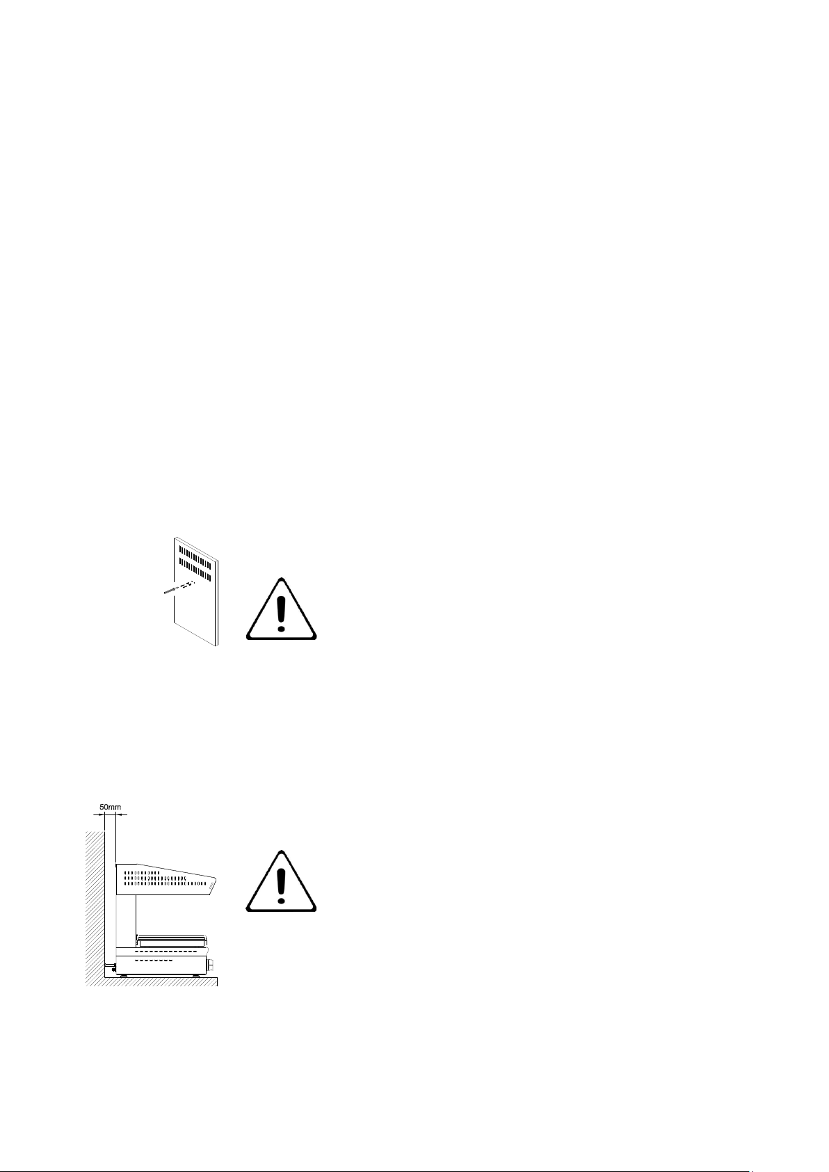
Before installing the appliance, remove the two
screws blocking the heating element from the back
(Refer to Figure 1)
Place the unit where it is going to be used, keeping it away from walls, flammable cladding
materials or other flammable parts.
Level and adjust the height of the unit by means of the levelling feet.
Remove the protective film from the outer panels, pulling it
away slowly so no traces of glue are left.
Do not obstruct the air flow or heat vents.
If you put the unit on a table, leave at least 50mm between
the back of the unit and rear wall (Refer to Figure 2).
Figure 1
Figure 2
Page 9
To wall mount the salamander use the wall-mounting brackets, fixings and inserts suitable for
the type of wall and unit weight.
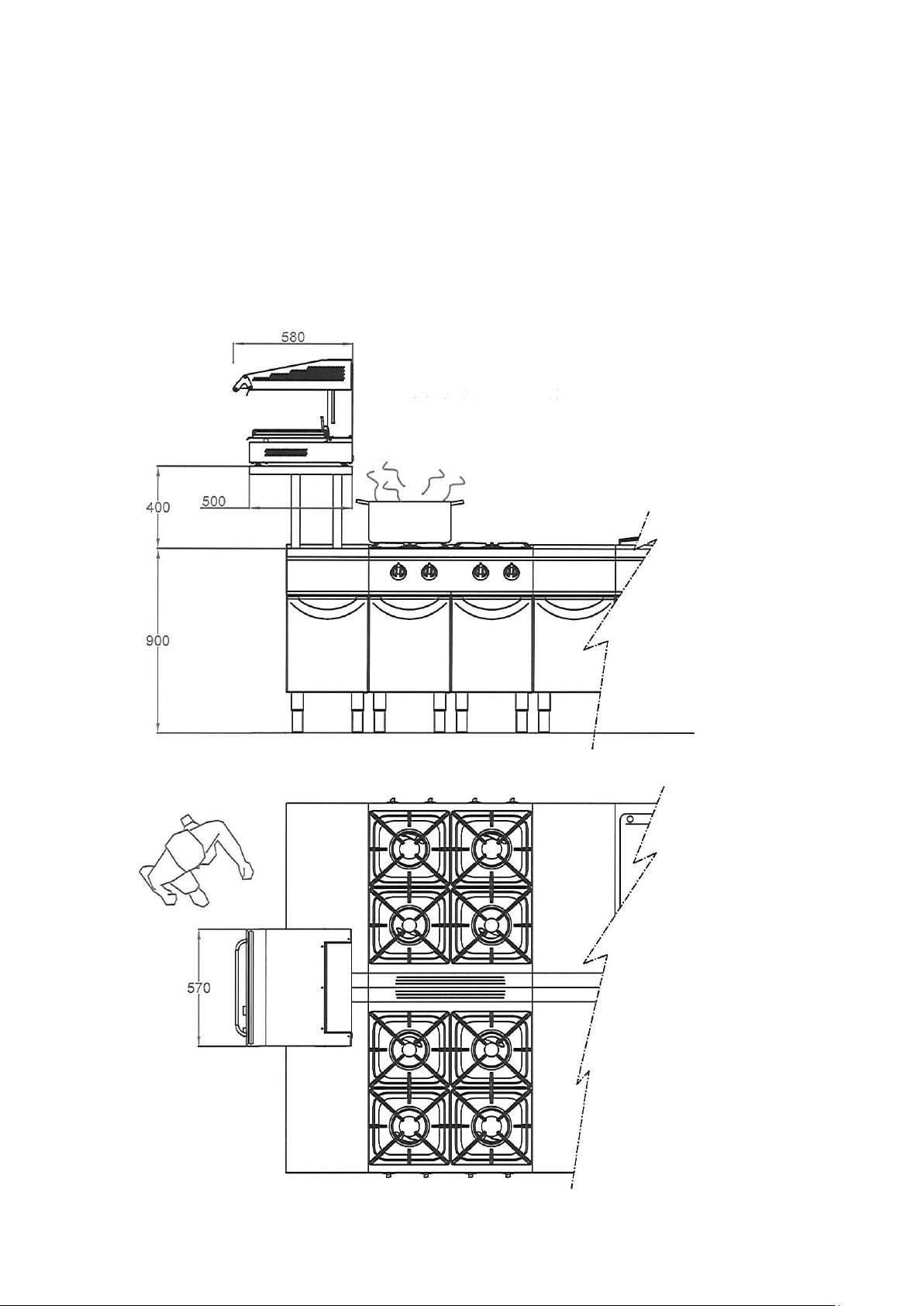
Locating the Grill
Direct steam must be prevented from interfering with the cooking process or entering the
controls compartment to damage the electrics.
Never locate the unit above a working hob where pans are boiling water or other liquids that
steam might emanate from. See diagram below.
Page 10

1.3 CONNECTING TO THE MAINS
Electrical rating: 4.5kW
Electrical supply voltage: 400V 3N~ 50/60Hz
Required electrical supply: 32A
Phase split: L1 6.52A, L2: 6.52A. L3: 6.52A
Single phase: 19.56A
- Before connecting unit to the mains, check that both voltage and frequency on
rating plate are suitable for use with the electrical supply available.
- The unit is delivered ready for use as indicated on rating plate located on the back.
- To connect grill to the mains, feed the cable (cut to correct length) through hole on
the back of the appliance and connect it to junction box on the right side. Fit the
required plug to comply with the electrical supply and connect it to a suitable outlet
that is properly earthed in accordance with current standards.
- For direct connection to the mains supply, it is necessary to install a 4-pole switch
between the unit and the mains, rated for the load with contacts that have a
minimum opening distance of 3mm.
When unit is running, check supply voltage is ± 10% of rated voltage value.
- In addition, the unit must be connected to an equipotential system which must be
checked following the guidelines of current regulations.
Page 11
SECTION 2 INSTRUCTIONS FOR E600 (fitted with plate)
The unit should only be used for the designated purpose. Any other use is improper.
Do not leave appliance unattended when in use.
2.1 GRILL FUNCTION
COOKING mode:
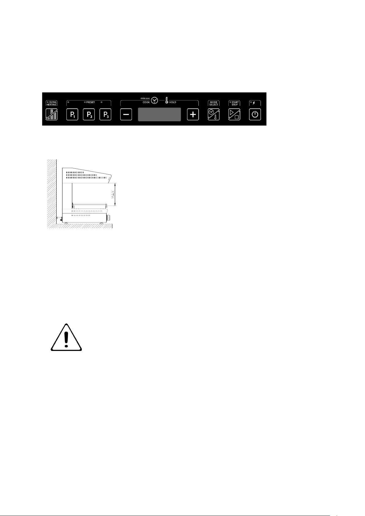
By adjusting the hood height, it is possible to regulate heat
upon food to be cooked. The greater the distance between the
food and the heating element - the lower the heat intensity.
HOLD mode:
The grill hood must be at the maximum height above hob level (Refer to Figure 4).
The alternating side heating elements keep food on the tray at the cooking temperature
reached during the cooking cycle.
The central section will pulse off and on during operation. This provides evenness of grilling
across the entire cooking surface.
2.2 SETTING
Before turning on the grill for the first time, remove all packaging
material and clean it thoroughly, removing any protective industrial
grease as follows:
- Clean unit with a damp sponge and a mild detergent.
- Rinse grill with clean water.
Figure 4
Figure 3
Page 12
2.3 USER INTERFACE
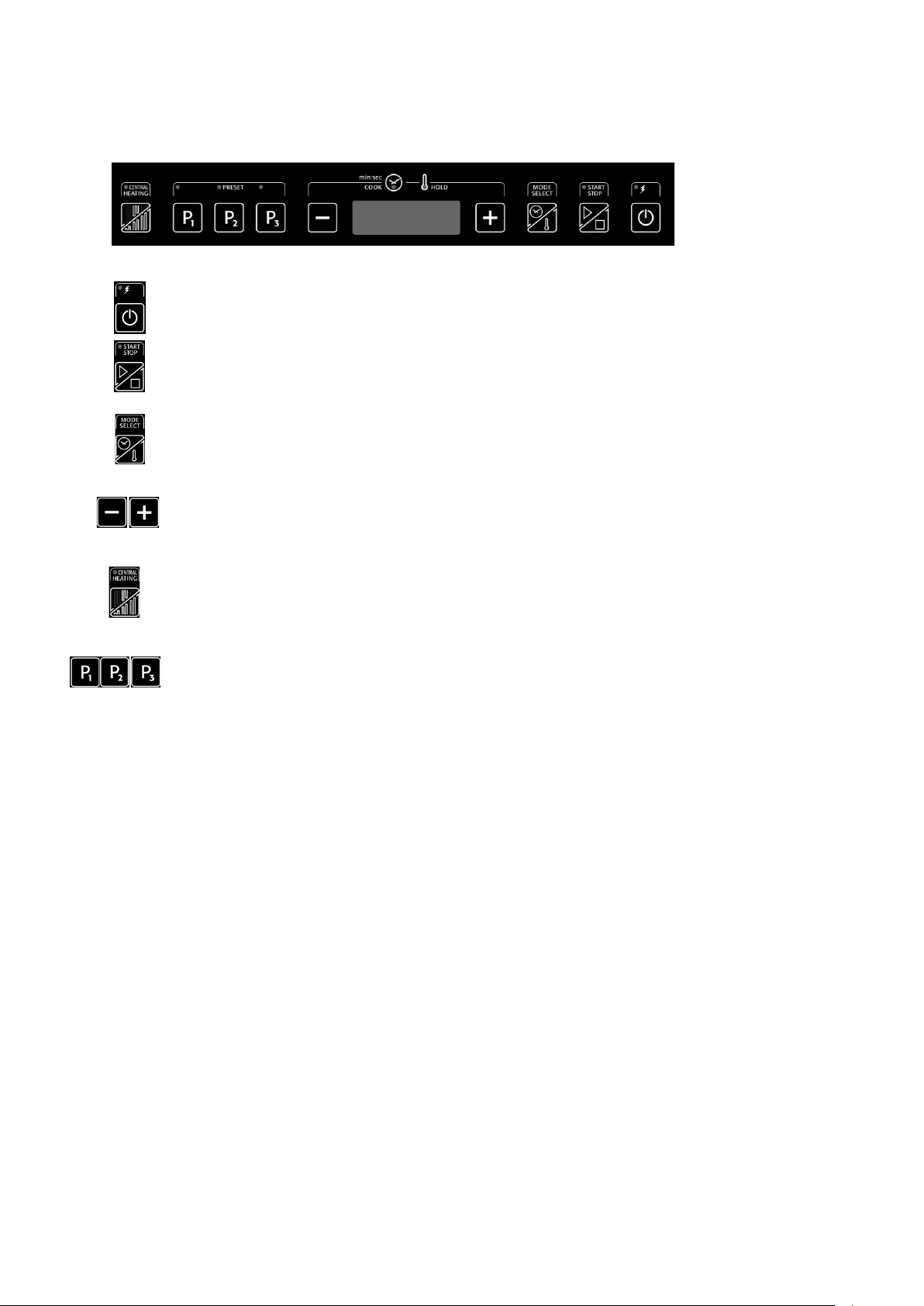
On/off button. When appliance is switched off - all functions are also switched off.
Start/stop button allows you to start or stop cooking and hold modes.
Mode select button allows you to select either cooking or hold modes in case of
manual cooking; in case of program selection you can pass from cooking mode to hold
mode and vice versa.
- - and + buttons increase or decrease cooking time and/or heat intensity of the hold
mode
Central heating button allows you to set the cooking session with all resistances or
just the central resistances.
Preset buttons cannot be used when the appliance is in START mode; thus the
following instructions only refer to ON or STOP mode; you can select a program by
briefly pressing the corresponding button. You can enter the program selection mode
by holding the button down; you can then save current settings and go back to normal
functioning by briefly pressing the same button again.
2.4 MANUAL MODE
Switch the grill on by pressing the ON/OFF button.
Press MODE SELECT button to select the type of mode (cooking or hold – the
corresponding LED above the display will come on).
Set time and intensity and press START or place the plate upon the plate detection device to
start the session (cooking mode will terminate once the set time ends and a buzzer will sound);
pressing the START/STOP button or removing the plate (the plate detection device switches
appliance off) will cause the HOLD mode to switch off.
AUTOMATIC MODE
Switch the grill on by pressing the ON/OFF button.
Select desired program by pressing P1, P2 or P3 button.
Press START or place the plate upon the plate detection device as in the manual mode.
Figure 5
Page 13
SETTING A PROGRAM
Switch the grill on by pressing the ON/OFF button.
Hold down desired program button (P1, P2 or P3) until display starts flashing.
Set cooking or hold mode by pressing SELECT/MODE button, then set time using the + and
– buttons.
If the cooking mode has been selected, it is possible to set a hold mode session at the end of
the cooking session by pressing SELECT/MODE button immediately after setting the time and
then setting heat intensity from 1 to 8. Save the program by pressing the button again. If you
press the program button again without setting a hold mode session first, the cooking session
only will be saved.
SWITCHING OFF
After use, switch off appliance using ON/OFF switch and omni-polar switch upstream of
appliance.
SECTION 3 CLEANING AND MAINTENANCE
BEFORE ATTEMPTING ANY MAINTENANCE, ISOLATE THE APPLIANCE AT
THE MAIN SWITCH AND TAKE STEPS TO ENSURE THAT IT IS NOT
INADVERTENTLY SWITCHED ON.
MAINTENANCE CHECK
Regular servicing of the appliance should be undertaken to ensure correct
operation, it is functioning as intended, and safe to use. We recommend
servicing after 2,500 hours of use, or annually, whichever comes first.
Any maintenance schedule should be carried out in accordance with SFG20
Maintenance Schedule. Should any issues with the integrity of the components be
identified these should be replaced. If the appliance is not considered safe the
unit should be removed from service and the responsible person advised why the unit is not safe to
use and what remedial action is needed. Contents of the maintenance schedule should be agreed
with the maintenance provider.
Page 14

3.1 ROUTINE MAINTENANCE
At the end of each working day, the unit must be cleaned both for reasons of hygiene
and also to prevent malfunctions.
Clean all stainless steel parts with warm, soapy water, rinse thoroughly and dry with
care. Do not use products that contain chlorine (e.g. bleach).
Do not clean unit with jets of water or high pressure water. Do not use metal cleaning
pads, brushes or scrapers made of ordinary steel. If necessary, use stainless steel
wool, rubbing in the direction of satin finish.
If unit is left unused for any length of time, apply a thin protective layer of Vaseline oil
over all stainless steel parts with a cloth and ensure that the room is regularly aired.
The glass should be cleaned regularly when cool. This will prevent staining.
Page 15
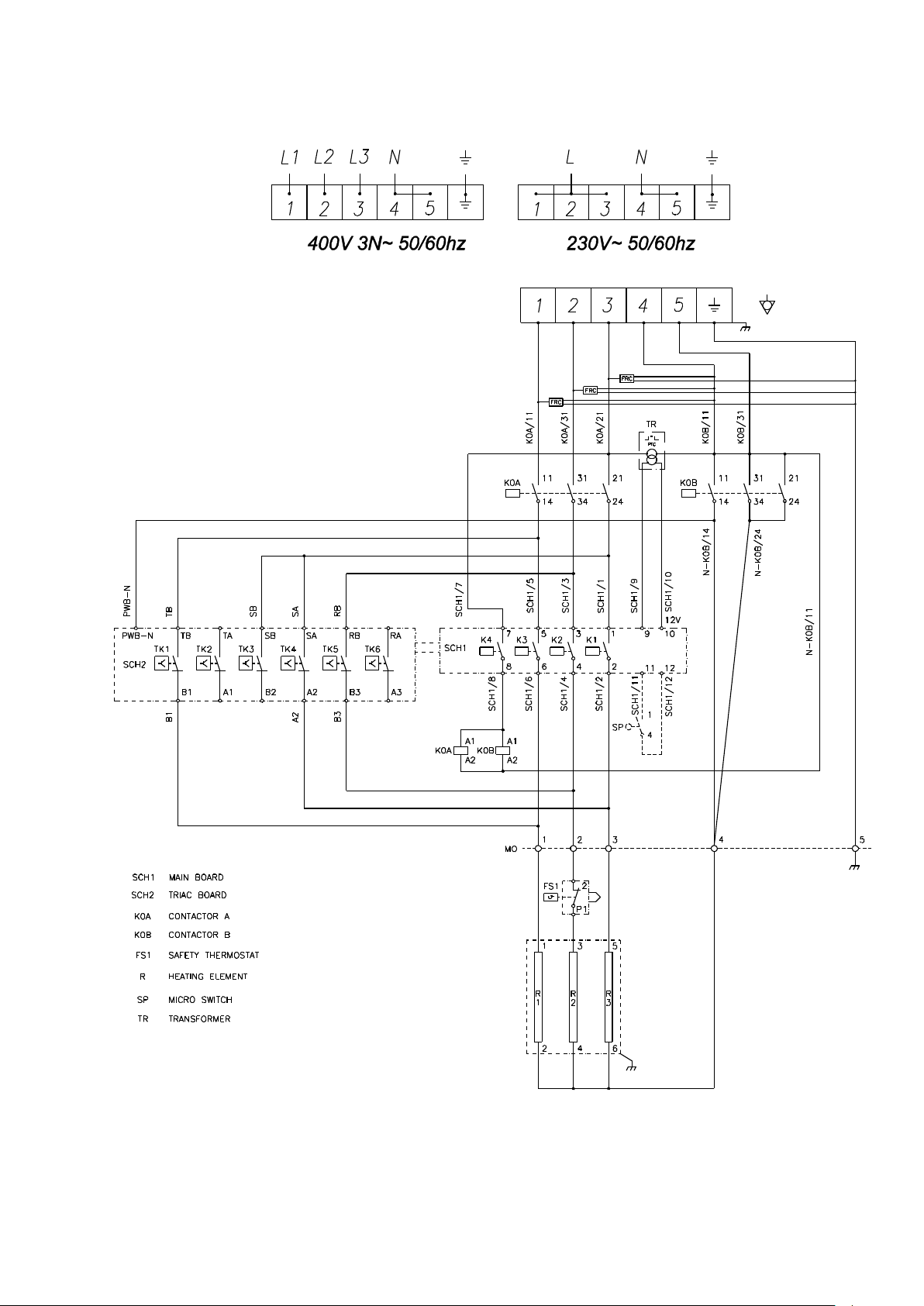
WIRING DIAGRAM
 Loading...