

Falcon E401, E402, E401F, E402F Installation, Servicing And User Instructions Manual
E401/E402
E401F/E402F FRYERS
INSTALLATION, SERVICING
and USER INSTRUCTIONS
IMPORTANT
The installer must ensure that the installation of the appliance is in conformity with these instructions
and National Regulations in force at the time of installation.
Particular attention MUST be paid to -
BS7671 IEE Wiring Regulations
Electricity at Work Regulations
Health And Safety At Work Act
Fire Precautions Act
This appliance has been CE-marked on the basis of compliance with the Low Voltage and EMC
directives for the voltages stated on the data plate.
WARNING -THIS APPLIANCE MUST BE EARTHED
On completion of the installation these instructions should be left with the Engineer-in-Charge for
reference during servicing. Further to this, The Users Instructions should be handed over to the User,
having had a demonstration of the operation and cleaning of the appliance.
IT IS MOST IMPORTANT THAT THESE INSTRUCTIONS BE CONSULTED BEFORE INSTALLING
AND COMMISSIONING THIS APPLIANCE. FAILURE TO COMPLY WITH THE SPECIFIED
PROCEDURES MAY RESULT IN DAMAGE OR THE NEED FOR A SERVICE CALL.
PREVENTATIVE MAINTENANCE CONTRACT
In order to obtain maximum performance from this unit we would recommend that a Maintenance
Contract be arranged with SERVICELINE. Visits may then be made at agreed intervals to carry out
adjustments and repairs. A quotation will be given upon request to the SERVICELINE contact
numbers below.
WEEE Directive Registration No. WEE/DC0059TT/PRO
At end of unit life, dispose of appliance and any replacement parts in a safe manner, via
a licenced waste handler. Units are designed to be dismantled easily and recycling of all
material is encouraged whenever practicable.
Falcon Foodservice Equipment
HEAD OFFICE AND WORKS
Wallace View, Hillfoots Road, Stirling. FK9 5PY. Scotland.
SERVICELINE CONTACT
Phone: 01438 363 000 Fax: 01438 369 900
T100750 Ref. 8

IMPORTANT INFORMATION
Warranty Policy Shortlist
Warranty does not cover :-
• Correcting faults caused by incorrect installation of a product.
• Where an engineer cannot gain access to a site or a product.
• Repeat commission visits.
• Replacement of any parts where damage has been caused by misuse.
• Engineer waiting time will be chargeable.
• Routine maintenance and cleaning.
• Gas conversions i.e. Natural to Propane gas.
• Descaling of water products and cleaning of water
or are fitted and not maintained.
• Blocked drains
• Independent steam generation systems.
• Gas, water and electrical supply external to unit.
• Light bulbs
• Re-installing vacuum in kettle jackets.
• Replacement of grill burner ceramics when damage has been clearly caused by misuse.
• Where an engineer finds no fault with a product that has been reported faulty.
• Re-setting or adjustment of thermostats when unit is operating to specification.
• Cleaning and unblocking of fryer filter systems due to customer misuse.
• Lubrication and adjustment of door catches.
• Cleaning and Maintenance
• Cleaning of burner jets
• Poor combustion caused by lack of cleaning
• Lubrication of moving parts
• Lubrication of gas cocks
• Cleaning/adjustment of pilots
• Correction of gas pressure to appliance.
• Renewing of electric cable ends.
• Replacement of fuses
• Corrosion caused by use of chemical cleaners.
2
sensors where softeners/ conditioners are not fitted,
SECTION 1 - INSTALLA
TION
TS
MANUFACTURER
INSTALLER.
are
caused
It
WEIGHTS
firm
fryer
possibility
applied.
installation,
means,
must
relative
provided
chain
bracket
floor
Bracket
clearance
combustible
clearance
edge
surface.
with
clearance
greater
largest
requirements
regulations.
requirements should
regulations
a
supply
code
be
incorporating
UNLESS OTHERWISE STATED, PAR
BEEN PROTECTED BY THE
NOT TO BE ADJUSTED BY THE
Please ensure that any plastic coatings
to use. Before operation, the pan
thoroughly cleaned and dried.
Discolouration of heated parts is
testing to ensure a satisfactory unit.
quality or performance.
1.1 MODEL NUMBERS, NETT
and DIMENSIONS
Model
E401 Fryer
E402 Fryer
E401F Fryer
E402F Fryer
Width
(mm)
400 800
400 800
400 800
400 800
Depth
(mm)
WHICH HAVE
ARE
removed prior
requires to be
by factory
does not affect
Height
(mm)
880 63
880 63
880 74
880 74
Weight
(kg)
1.2.2 Clearances
The unit requires a
rear between unit and any
A minimum vertical
allowed between top
overlying combustible
Important
If fryer is to be installed
instructions for each unit
determine the necessary
wall or overlying surface.
Some appliances require
than others. The
determine overall distance
adjoining appliances.
1.3 VENTILATION
The appliance ventilation
with national and local
of at least 100mm to the
wall.
of 750mm should be
of flue outlet and any
other appliances then the
should be consulted to
to any combustible
clearance distances
clearance will therefore
for a complete suite of
should be in line
1.2 SITING
The unit must be installed on a
well-lit draught free position. The
installed in a position where the
tipping is likely when force is
restraint may be the manner of
connection to a battery of appliances
fryer in an alcove, or by separate
quate ties.
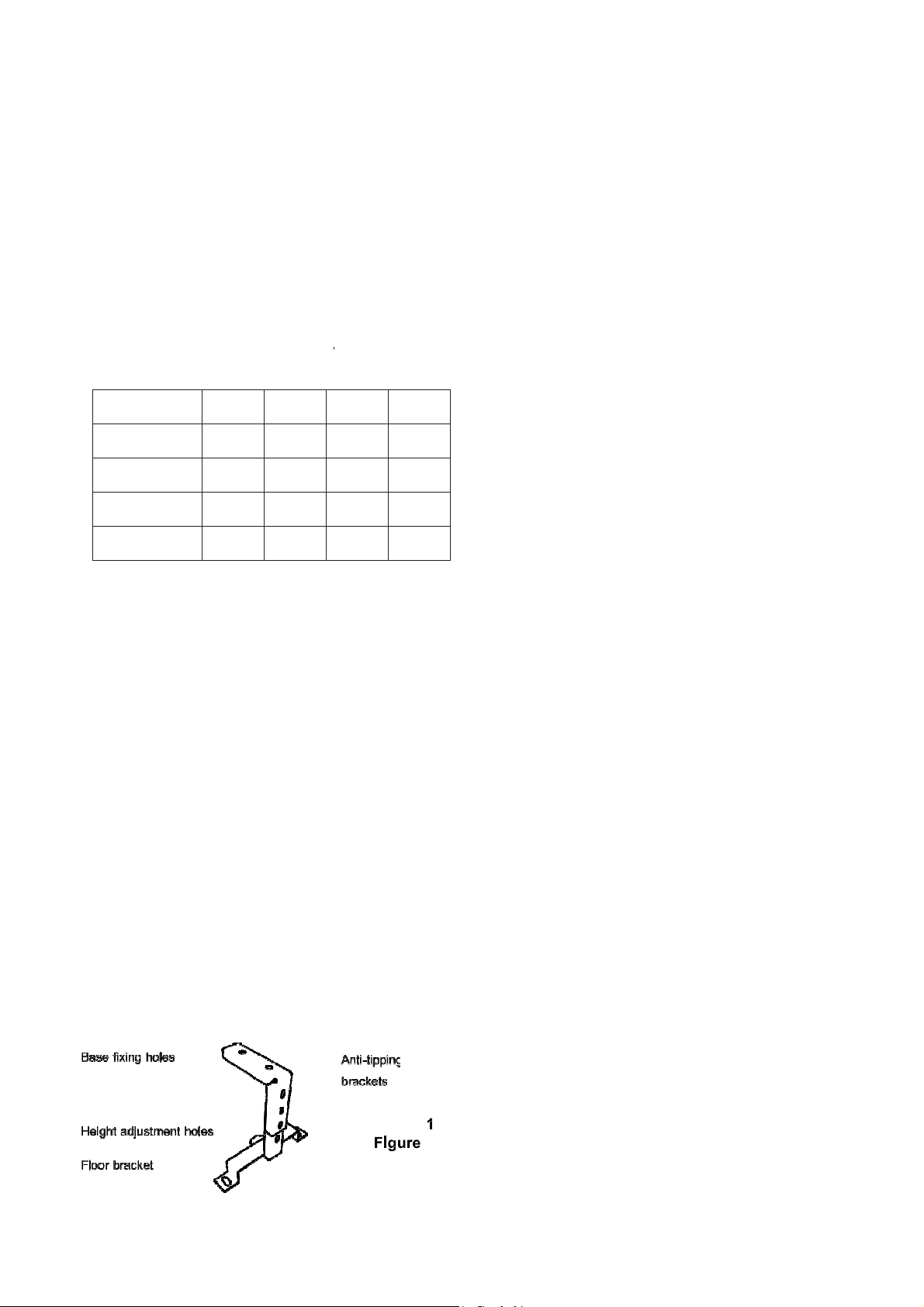
1.2.1 Anti-tipping Bracket
An anti-tipping mechanism is also
accessory. If fitted, the brackets
locate the fryer in the correct position
as detailed below. Fixing holes are
to accommodate the bracket. Details
found in Figure 1 below. The retaining
release eyelet. Attach securely to fixing
bracket to floor after alignment with
the fryer. Adjust bracket to slide below
Figure 1 - Anti-tipping
level floor in a
should not be
of sideways
The means of
such as
or installing the
such as ade-
available as an
be installed to
to any walls
in fryer base
of fitting can be
has a quick
point and secure
attached to
bracket.
For multiple installations,
together. Installations should
local and/or national
A competent engineer must
work.
1.4 ELECTRICAL SUPPLY
The unit is supplied with
connection to a 400V 3N~
isolating switch.
Phase Loading
L1: 29A, L2: 29A, L3: 29A
1.5 CABLE SUPPLY
A cable conforming to
(eg. H07RH-F5G4) must
400V 3N~ supply
be added
be made in accordance with
applying at the time.
be used for any installation
2 metre 5-core cord for
incorporating a suitable
designation 0245 IEC 57
used for connection to a
a suitable isolating switch.
SECTION 2 - ASSEMBLY and
COMMISSIONING
The electrical cable must be connected in accordance
with the various regulations listed on the cover of this
manual.
2.1 ASSEMBLY
a) Unpack appliance
b) Unpack fryer baskets and accessories.
c) Place element guard and baskets in pan.
d) Level appliance and fit all service protection kits.
(Anti-tilt kit, if ordered as accessory).
2.2 CONNECTION TO AN ELECTRICAL SUPPLY
The supply cable must be connected to a suitable
isolator switch as follows:
Phase 1: Brown, Phase 2: Black, Phase 3: Grey
Neutral: Blue, Earth: Green/Yellow
2.3 STARTING UP
2.3.1 E401/401F Fryer Control Panel (See Figure 2)
3
2
1
4
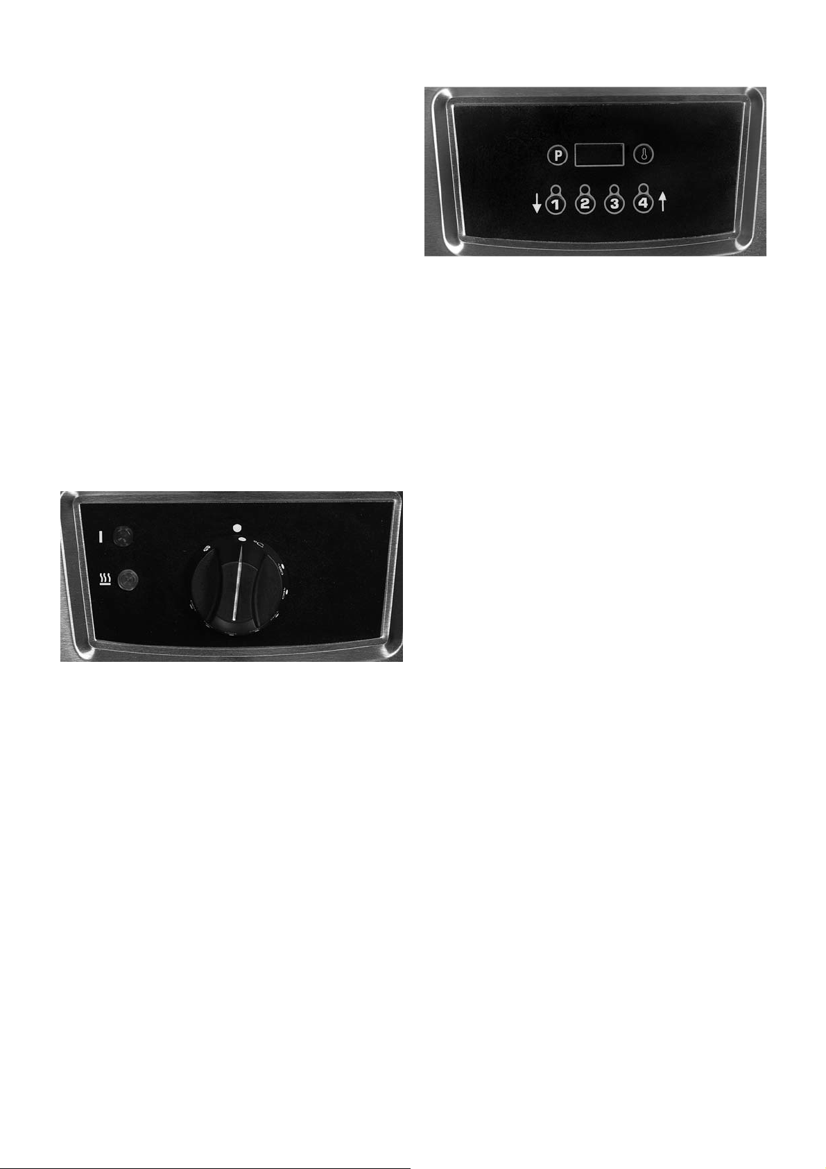
2.3.2 E402/402F Fryer Control Panel (See Figure 3)
1 / 5
2
4
Figure 3 – E402/402F Control Panel
1.
Four Digit LED Display
Displays Set temp, Actual temp, cook time remaining and
also used for programming purposes.
2.
Program Button
Used to enter timer programme mode (to change each of
the 4 pre-set timer select channels). (See Section 6).
3.
Temperature Button
Used to view Actual/Set temperature and also to enter
Set temperature mode (See Section 6).
4.
Timer Keys (1 – 4)
Used to start/cancel pre set cook times. Buttons 1 & 4
also used to change times or temperatures when in
either set mode (See Section 6).
5.
Heat demand LED indicator
3
Figure 2 – E401/401F Control Panel
1.
ON/OFF and Temperature Control Knob
Temperature Selection (140 - 190°C). (Unit is off when in
position indicated).
2.
Fat Melt Position
Feature for slow pulsed heating of solid fats.
3.
Power on indicator.
4.
Heat Demand Indicator
illuminates when thermostat demands heat, i.e. oil
temperature is more than 5⁰C below temperature setting.
Extinguishes when desired temperature is reached.
4
Illuminates when thermostat demands heat,
i.e. oil temperature is more than 2⁰C
set temperature. Will extinguish when desired setting is
reached.
below programmed
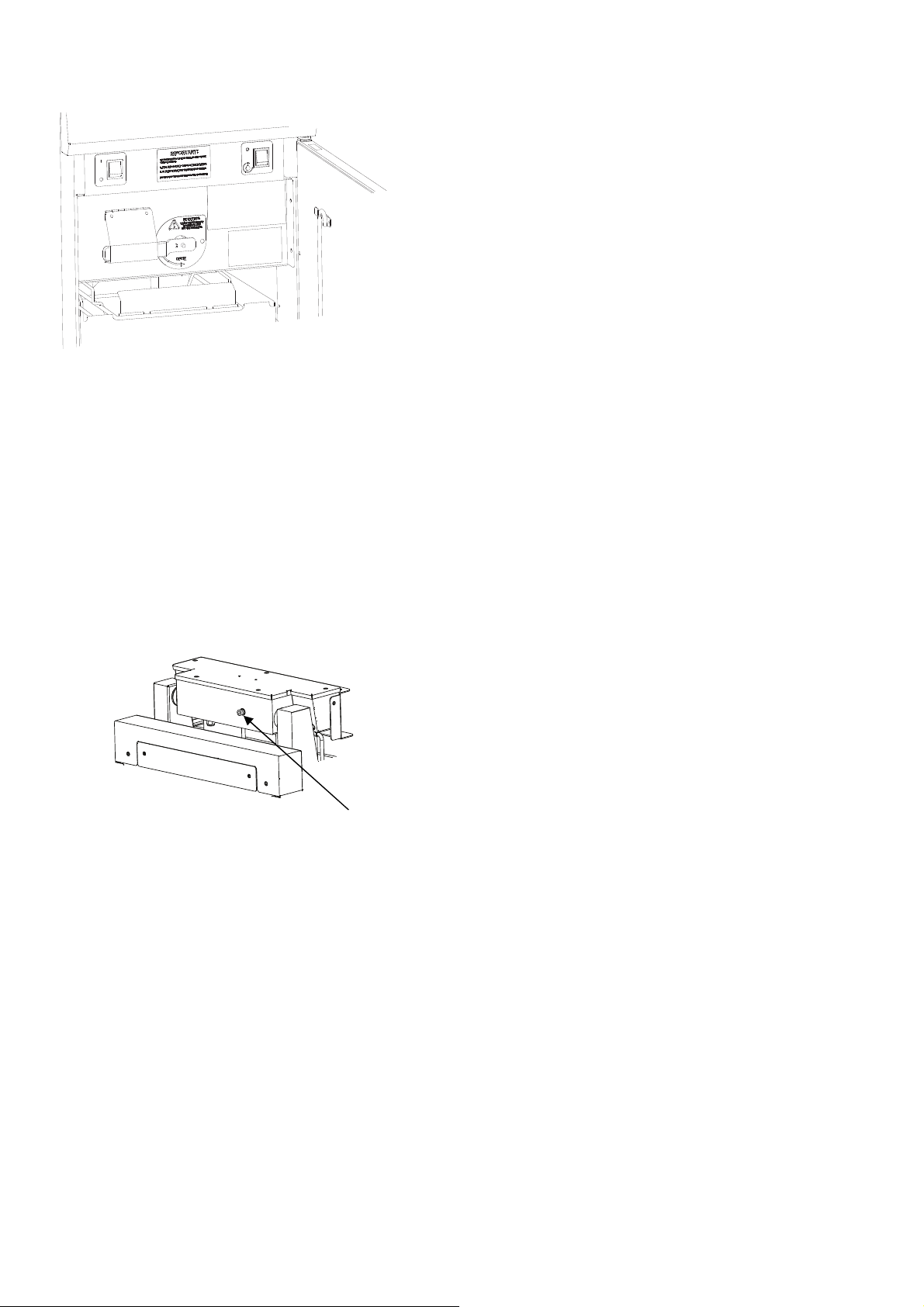
2.3.3 All models - Additional Controls (See
Figure 4)
Figure 4 – All models - Additional Controls
The following additional controls are located behind
cabinet door.
1.
Fryer ON/OFF Switch
Cuts power to appliance.
2.
Filtration Pump Switch – E401F & E402F only
Energises filtration pump.
3.
Temperature Safety Limiter Reset Button
Located on rear of element box, below black dust cap,
refer to Figure 5.
Figure 5
2.3.4 E401/401F Controller Diagnostic
Indicators (Refer to Wiring Diagrams)
On PCB Controller
safety button
2.4 PRE-COMMISSIONING CHECK
2.4.1 Checking Controller Operation
To check operation of controls, refer to Using The
C
ontroller - Section 6.2.1.
2.4.2 Checking Oil Filtration Pump E401F & E402F
only.
To check operation of oil filtration pump, refer to
Section 7.
2.5 TEMPERATURE LIMIT THERMOSTAT
The unit is equipped with an additional temperature
thermostat, independent of the main controller.
In the case of operating thermostat failure, allowing oil
temperature to rise above predetermined legislation safe
zone (230⁰C), limit device will activate and cut power to
controller and elements.
To re-set temperature limit thermostat: (Refer to Figure 5)
All models
a) Turn fryer ON/OFF switch to OFF position.
b) Allow oil to cool below 180⁰C
c) To reset limit thermostat, remove black dust cap
located at element box rear. Push reset button using a
blunt instrument. (i.e. a pen) and replace cap.
d) Turn fryer ON/OFF switch to ON position.
e) Reselect temperature.
f) If limit thermostat reactivates carry out fault f
temperature control circuitry.
limit
inding on
2.6 INSTRUCTION TO USER
After installing and commissioning appliance, please
hand Instructions to user or purchaser and ensure that
the person(s) responsible understands the instructions to
correctly operate and clean unit in a safe manner.
CR2,Green LED ‘ON’ indicates heat demand.
CR2,Green LED ‘OFF’ indicates no heat demand.
CR9,Red LED flashes if temperature probe is either
short or open circuited.
CR9,Red LED is permanently ‘ON’ to indicate system is
OK. Set point is +/-7⁰C of mid-set point.
Emphasis should be given to safe operation and use of
drain valve and oil bucket. Oil bucket should not be
overfilled to allow safe movement. Oil should be allowed
to cool before any manual handling.
Note: The oil container may be heavy. Drain small
amounts at a time if necessary, before lifting container.
Manual handling regulations should be observed.
5

SECTION 3 SERVICING AND CONVERSION
BEFORE ATTEMPTING ANY SERVICING, TURN OFF
THE ELECTRICAL SUPPLY. TAKE STEPS TO ENSURE
THAT THESE CANNOT BE INADVERTENTLY TURNED
ON.
AFTER ANY MAINTENANCE TASK, CHECK THE
APPLIANCE TO ENSURE THAT IT PERFORMS
SAFELY AND CORRECTLY AS DESCRIBED IN
SECTION 2.5.
3.1 INTEGRAL COMPONENTS
3.10 MAINS ON and HEAT DEMAND NEONS
a) Remove control panel by undoing fixings at top an
bottom of control panel and unplug control panel.
b) Remove electrical connections from neon. Undo neon
retention nut.
c) Carefully replace in reverse order.
3.11 DRAIN VALVE
a) Ensure fry pot is empty. Refer to Section 8.
b) Remove nut from handle and lift handle off.
c) Remove front panel fasteners.
d
The following parts must be checked and serviced
regularly:
1.
Oil ingress to electrical components.
2.
Visual inspection of components and fryer pan.
3.
Temperature limit thermostat calibration.
3.2 ACCESS PROCEDURES
Before removal of any fryer components:
a) Ensure appliance electrical supply has been shut off
and cannot be accidentally turned back on.
b) Allow oil to cool before any operation that requires pan
to be drained.
c) Only use parts specified by the manufacturer.
d) All components replaced MUST be fully checked after
fitting to ensure safe operation.
e) A full pre-commissioning check as detailed in Section
2.5 should be carried out.
3.3 ELEMENTS
d) Disconnect wiring, noting all connections.
e) Remove front panel to access drain valve.
f) Undo drain pipe. Use appropriate size of spanner
remove drain valve.
g) Replace in reverse order and check for oil leaks.
3.12 FILTRATION PUMP
a) Remove rear access panel. Disconnect pipe at filtration
pump.
b) Disconnect electrical coupling plug and start capacitor
connections.
c) Remove nuts from pump mounting bolts (accessed
through fryer door at rear of oil bucket compartment)
and lift pump clear.
d) Disconnect pump from bracket. Replace in reverse
rder. Note: Remember to check for oil leaks before
o
replacing any panels.
3.13 TEMPERATURE LIMIT THERMOSTAT
a) Remove element box cover plate.
to
a) Remove five fixings from element box top and release
element cables.
b) Tilt element box and rest in upright position.
c) Remove four fixings from element mounting plate.
d) Remove element and seal.
e) Replace in reverse order.
3.9 TEMPERATURE CONTROLLERS
a) Remove control panel by undoing fixings at top and
bottom of control panel and unplug control panel.
b) Disconnect electrics loom and remove fixings
to
enable controller to be removed.
c) Carefully replace in reverse order.
b) Lift elements and secure in raised position.
c) Undo phial retention nut.
d) Release phial from retaining clip.
e) Disconnect phial wire plug and cut off plug.
f) Pull down phial to remove.
g) Carefully replace in reverse order. Check for any oil
leaks and that thermostat calibration is within
specification.
3.8 CONTACTORS & FILTRATION PUMP TIMER
a) Remove 8 fixings from rear control compartment cove
a) Disconnect wiring from faulty component, noting all
connections.
b) Replace and rewire component.
c) Replace cover.
r.
6
 Loading...