

Page 1
E3830 and E3860
DOMINATORPLUS Fryers
INSTALLATION and
SERVICING INSTRUCTIONS
IMPORTANT
The installer must ensure that the installation of the appliance is in conformity with these instructions
and National Regulations in force at the time of installation. Particular attention MUST be paid to:
BS7671 IEE Wiring Regulations
Electricity at Work Regulations
Health And Safety At Work Act
Fire Precautions Act
This appliance has been CE-marked on the basis of compliance with the Low Voltage and EMC
Directives for the voltages stated on the data plate.
WARNING: THIS APPLIANCE MUST BE EARTHED.
On completion of the installation, these instructions should be left with the Engineer-in-Charge for
reference during servicing. Further to this, The Users Instructions should be handed over to the User,
having had a demonstration of the operation and cleaning of the appliance.
IT IS MOST IMPORTANT THAT THESE INSTRUCTIONS BE CONSULTED BEFORE INSTALLING
AND COMMISSIONING THIS APPLIANCE. FAILURE TO COMPLY WITH THE SPECIFIED
PROCEDURES MAY RESULT IN DAMAGE OR THE NEED FOR A SERVICE CALL.
PREVENTATIVE MAINTENANCE CONTRACT
In order to obtain maximum performance from this unit we would recommend that a maintenance
contract be arranged with SERVICELINE. Visits may then be made at agreed intervals to carry out
adjustments and repairs. A quotation will be given upon request to the contact numbers below.
WEEE Directive Registration No. WEE/DC0059TT/PRO
At end of unit life, dispose of appliance and any replacement
parts in a safe manner, via a licenced waste handler.
Units are designed to be dismantled easily and recycling of all
material is encouraged whenever practicable.
Falcon Foodservice Equipment
HEAD OFFICE AND WORKS
Wallace View, Hillfoots Road, Stirling. FK9 5PY. Scotland.
SERVICELINE CONTACT
Phone: 01438 363 000 Fax: 01438 369 900
T100774 Ref. 5
Page 2

IMPORTANT INFORMATION
Warranty Policy Shortlist
Warranty does not cover :-
• Correcting faults caused by incorrect installation of a product.
• Where an engineer cannot gain access to a site or a product.
• Repeat commission visits.
• Replacement of any parts where damage has been caused by misuse.
• Engineer waiting time will be chargeable.
• Routine maintenance and cleaning.
• Gas conversions i.e. Natural to Propane gas.
• Descaling of water products and cleaning of water sensors where softeners/ conditioners are not fitted,
or are fitted and not maintained.
• Blocked drains
• Independent steam generation systems.
• Gas, water and electrical supply external to unit.
• Light bulbs
• Re-installing vacuum in kettle jackets.
• Replacement of grill burner ceramics when damage has been clearly caused by misuse.
• Where an engineer finds no fault with a product that has been reported faulty.
• Re-setting or adjustment of thermostats when unit is operating to specification.
• Cleaning and unblocking of fryer filter systems due to customer misuse.
• Lubrication and adjustment of door catches.
• Cleaning and Maintenance
• Cleaning of burner jets
• Poor combustion caused by lack of cleaning
• Lubrication of moving parts
• Lubrication of gas cocks
• Cleaning/adjustment of pilots
• Correction of gas pressure to appliance.
• Renewing of electric cable ends.
• Replacement of fuses
• Corrosion caused by use of chemical cleaners.
Page 3
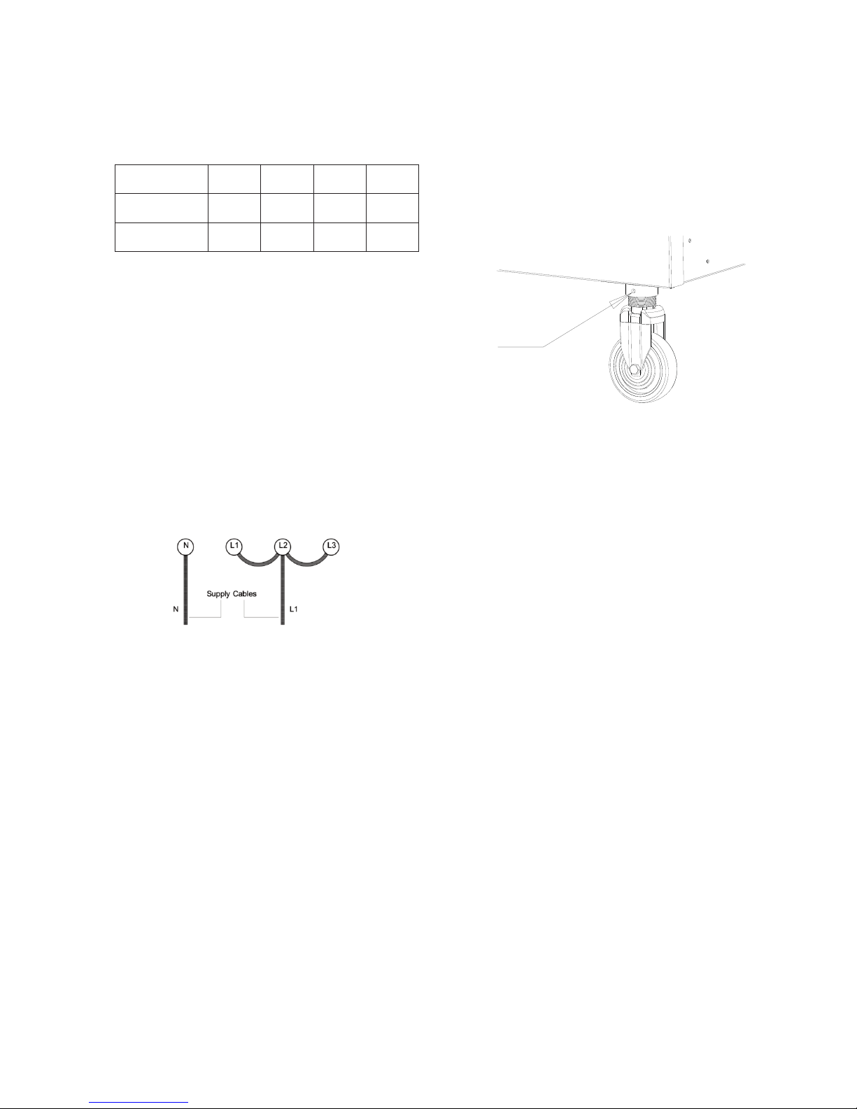
Castors
Undo grub screw and use a spanner to adjust the castor
height. Turn clockwise to raise level and anti-clockwise
to lower.
Secure grub screw when task is completed.
2.2 CONNECTION TO THE ELECTRICAL SUPPLY
To gain access to terminals, proceed as follows:-
Remove fixings at unit rear to remove cover and access
electrical connections.
Undo cable gland.
Feed cable through cable gland into electrical box.
Connect leads to respective terminals.
Tighten cable gland.
Replace cover.
If single phase connection is required, refer to Section 1.3
for details.
2.3 COMMISSIONING
Fill pan with oil to mark on element guard
(i.e. approximately 20 litres for E3830 model and 40 litres
for E3860 model) and switch on at isolator switch.
Turn thermostat to maximum setting and check that it
operates at the correct temperature of 190°C.
The importance of never switching on the elements
unless they are covered by oil or water must be stressed.
DO NOT USE SOLID FAT.
2.4 INSTRUCTION TO USER
After installing and commissioning appliance, hand user
instructions to user or purchaser.
Ensure that person(s) responsible is (are) made familiar
with use and maintenance of unit.
1.1 MODEL NUMBERS, NETT WEIGHTS
and DIMENSIONS
1.2 SITING
Before connecting appliance to electricity supply, it must
be correctly positioned and levelled. Levelling is effected
by turning the lower area of the adjustable legs.
If desired, feet that allow floor-fixing may be specified at
time of order.
1.3 ELECTRICAL CONNECTION
The unit is designed for use on AC supplies only and
terminals are normally arranged for either 2 phase
operation (E3830 model) or 3 phase (E3860 model).
If single phase supply has been specified, a bridging link
is provided with the appliance and should be connected
as detailed below.
Cable entry is located at appliance rear in the form of a
cable gland.
A suitably rated isolating switch with contact separation of
at least 3mm in all poles must be installed. All wiring must
be executed in accordance with regulations listed on title
page of this document.
Warning - This appliance must be earthed.
1.4 ELECTRICAL RATINGS
The electrical rating is stated on appliance data plate.
SECTION 2 ASSEMBLY and COMMISSIONING
2.1 ASSEMBLY
The appliance is supplied complete and ready to be
connected to the mains supply.
Position unit in desired location and level it. Turn lower
section of each leg clockwise to raise corresponding
corner height or anti-clockwise to lower it.
Model
Width
(mm)
Depth
(mm)
Height
(mm)
Weight
(kg)
E3830 Fryer
300 770 890 45
E3860 Fryer
600 770 890 73
SECTION 1 - INSTALLATION
UNLESS OTHERWISE STATED, PARTS WHICH HAVE BEEN PROTECTED BY THE MANUFACTURER
ARE NOT TO BE ADJUSTED BY THE INSTALLER.
Grub
screw
Page 4

SECTION 3 - SERVICING and
MAINTENANCE
BEFORE ATTEMPTING ANY MAINTENANCE TASK,
ISOLATE THE APPLIANCE AT THE MAIN SUPPLY.
TAKE STEPS TO ENSURE THAT IT MAY NOT BE
INADVERTENTLY SWITCHED ON.
3.1 ELECTRICAL CONTROL GEAR
The terminals are located at rear of unit. The contactor is
contained within box at front.
To gain access, open door and remove cover panel
behind.
The control thermostat and neon lamps are mounted on
the facia panel, which is secured by four fixings.
3.2 NEON INDICATOR LAMPS
These must be replaced by new lamps in event of failure.
To replace a faulty lamp, first remove facia panel and pull
off push-on terminals. Remove lamp by undoing fixing nut
at rear.
3.3 THERMOSTATS
The fryer has two thermostats.
The adjustable control thermostat is mounted upon
control panel.
The safety thermostat is located within the element box.
It has a fixed setting and manual re-set button at rear of
element box. In the event of control thermostat failure and
resultant overheating of frying medium, safety
thermostat will trip supply to elements before oil
temperature becomes dangerous.
To restore circuit having rectified the fault,
it is necessary to press the re-set button. This is situated
within the turret which projects through element box rear.
The oil must be allowed to cool to enable safety
thermostat to be re-set.
A defective safety or control thermostat cannot be
repaired and must be replaced. The capillary tubes pass
through pan wall and are sealed with small glands which
must not be overtightened. The phial must be fixed in
position within pan before tightening gland. The phial tip
should protrude from protective tube by 33mm.
Thermostat capillary tube must be covered with sleeve
insulation. Safety stat phial should be located centrally
within element clip.
3.4 CONTACTOR
This should require little or no maintenance under normal
circumstances. After long service, the burner contacts
may become pitted and at that point, new contacts should
be fitted.
3.5 ELEMENTS
These are individually replaceable. Access to terminals
and fixing nuts is gained upon removing element box
cover. When fitting a new element, ensure that sealing
gasket is fitted and tighten fixing nut firmly, preferably with
the aid of a tubular box spanner or socket.
When re-fitting element box cover, check condition of oil
resistant gasket. Do not use excessive force when
securing cover as this may deform it and allow oil to enter
box.
3.6 CLEANLINESS
To maintain maximum performance, the pan must be kept
clean. Periodically, oil must be drained off and the pan
should be filled with water and detergent. Boil up contents
and drain whilst still hot before flushing out with clean
water. Thoroughly dry pan and all fittings before re-filling
with oil. The elements can be lifted and hinged backward
to gain full access to all surfaces of pan and elements.
3.7 TILT SWITCH
Located in element terminal box, this component should
require no maintenance.
SECTION 4 - SPARES
When ordering spares, quote the unit type and serial
number. This information will be found on data plate
located on cover panel behind door.
An identity label is also provided on front frame.
Page 5

E3830 WIRING DIAGRAM
Page 6

E3860 WIRING DIAGRAM
(4 Element Version)
Page 7

MAINS TERMINAL BLOCK
25
24
23
22 27
16
3
2
1
19
252423 2722
16
321
19
26
AMBER NEON
1521
RED NEON
17
21
OPERATING STAT
18 20
CONTACTOR
A1 A2
7
9
810
15
17
28
18
11
TERMINAL BLOCK
28
14
TILT SWITCH
SAFETY STAT
2014
ELEMENT
9
ELEMENT
8
ELEMENT
7
ELEMENT BOX
ELEMENT
10
ELEMENT
11 26
E3860 WIRING DIAGRAM
(5 Element Version)
Page 8

H
H
L1 L2
N
1
3
5
1314
6
4
2
1
2
CONTACTOR
IMO MC-14-S-10
7
8
RH ELEMENT
5kW @ 230V
14
13
5
RED NEON
12, 15
A1A2
10
SAFETY STAT
(TRIP POINT
230 ° C)
OPERATING STAT
(0 °
C - 190
° C)
9 16 11
TILT SWITCH
(LOWERED POSITION)
18
6 15
AMBER NEON
1
2
3
4
5
6
7
5
2
1
9
16 11
6, 18
12
15
10
13
147
8
LH ELEMENT
5kW @ 230V
1
2
6
7
354
17
ELEMENT
BOX
E3830 CIRCUIT DIAGRAM
Page 9

H
H
H
H
ELEMENT
BOX
27
4
5
3A
2A
1
7
8, 15
25, 26
16, 23, 24
16, 23, 24
16, 17, 21
16, 17
28
1420
3
1
19
AMBER NEON
21
15
28
TILT SWITCH
(LOWERED POSITION)
142018
OPERATING STAT
(0 °
C - 190
° C)
SAFETY STAT
(TRIP POINT
230 ° C)
16, 17
A1 A2
17, 21
RED NEON
19
23
26
7
8
CONTACTOR
IMO MC-24-S-00
1
3
1
3
5 6
4
2
N
L2L1 L3
2
2, 18
2510
249
9, 10
16, 23, 24
25, 26
ELEMENT POSITIONS ARE WHEN VIEWED FROM FRONT OF APPLIANCE
H1 - OUTSIDE LH ELEMENT ( 5kW @ 230V )
H2 - CENTRE LH ELEMENT ( 5kW @ 230V )
H3 - CENTRE RH ELEMENT ( 5kW @ 230V )
H4 - OUTSIDE LH ELEMENT ( 5kW @ 230V )
1
2
3
4
2B
3B
E3860 CIRCUIT DIAGRAM
(4 Element Version)
Page 10

H
H
H
H
H
ELEMENT
BOX
27
7, 8
10, 11
25
23
16
26
15, 28
1420
3
1
19
AMBER NEON
1521
28
TILT SWITCH
(LOWERED POSITION)
142018
OPERATING STAT
(0
°
C - 190
°
C)
SAFETY STAT
(TRIP POINT
230
°
C)
16, 17
A1 A2
17, 21
RED NEON
19
23
25
8
10
CONTACTOR
IMO MC-24-S-00
1
3
1
3
5 6
4
2
N
L2L1 L3
2
2, 18
2611
2499 24
ELEMENT POSITIONS ARE WHEN VIEWED FROM FRONT OF APPLIANCE
H1 - OUTSIDE LH ELEMENT ( 3.65kW @ 230V )
H2 - INSIDE LH ELEMENT ( 3.65kW @ 230V )
H3 - CENTRE ELEMENT ( 3.65kW @ 230V )
H4 - INSIDE RH ELEMENT ( 3.65kW @ 230V )
H5 - OUTSIDE RH ELEMENT ( 3.65kW @ 230V )
2
1
3
4
17
17
227
5
22
E3860 CIRCUIT DIAGRAM
(5 Element Version)
 Loading...