

Page 1
T100839 Rev.8
DATE PURCHASED:
MODEL NUMBER:
SERIAL NUMBER:
DEALER:
SERVICE PROVIDER:
USERS, INSTALLATION AND SERVICING INSTRUCTIONS
ELECTRIC BRATT PAN
E3800
Page 2
SYMBOLS
PLEASE READ THIS MANUAL
This manual should be read carefully before operating, installing
or servicing the appliance.
WARNING!
Please pay particular attention to sections of the manual which
has this Warning symbol. If ignored, it may result in personal
injury or damage to the appliance.
Dear Customer,
Thank you for choosing Falcon Foodservice Equipment.
This manual can be downloaded from www.falconfoodservice.com where you
also can see the full range of our products and latest news.
IMPORTANT: Please keep this manual for future reference.
WEEE Directive Registration No. WEE/DC0059TT/PRO
At end of appliance life, dispose of appliance and any replacement parts in a safe
manner, via a licensed waste handler. Appliances are designed to be dismantled
easily and recycling of all material is encouraged whenever practicable.
Falcon Foodservice Equipment
HEAD OFFICE AND WORKS
2
Page 3

Wallace View, Hillfoots Road, Stirling. FK9 5PY. Scotland.
SERVICELINE CONTACT
Phone: 01438 363 000
CONTENTS
INTRODUCTION .................................................................................................................................. 4
OPERATION ......................................................................................................................................... 6
Controls .............................................................................................................................................. 7
Using the Bratt Pan .......................................................................................................................... 7
GETTING THE MOST OUT OF THE APPLIANCE ........................................................................ 8
CLEANING AND MAINTENANCE .................................................................................................... 9
SPECIFICATION .................................................................................................................................. 9
Model Number covered in this group of products ..................................................................... 10
Technical Data ................................................................................................................................ 10
DIMENSIONS / ELECTRICAL CONNECTION LOCATIONS ..................................................... 10
INSTALLATION .................................................................................................................................. 10
Unpacking ........................................................................................................................................ 11
Siting / Clearances ......................................................................................................................... 11
Electric Supply & Connection ....................................................................................................... 12
Water Supply................................................................................................................................... 12
Assembly ......................................................................................................................................... 12
Commissioning ............................................................................................................................... 13
SERVICING......................................................................................................................................... 13
Wiring Diagram(s) .......................................................................................................................... 20
FAULT FINDING ................................................................................................................................ 20
SPARE PARTS................................................................................................................................... 23
SERVICE INFORMATION ................................................................................................................ 24
3
Page 4

INTRODUCTION
This appliance has been CE-marked on the basis of compliance with
the Low Voltage and EMC Directives for the voltages stated on the
data plate as shown below:
IMPORTANT!
4
Page 5

It is most important that these instructions be consulted before
operating, installing and commissioning this appliance. Failure to
comply with the specified procedures may result in damage or the
need for a service call.
The installer must ensure that the installation of the appliance is in conformity with
these instructions and National Regulations in force at the time of installation.
Particular attention MUST be paid to: BS7671 IEE Wiring Regulations, Electricity
at Work Regulations, Health And Safety At Work Act, Fire Precautions Act.
TO PREVENT SHOCKS, ALL APPLIANCES MUST BE EARTHED.
This equipment is ONLY FOR PROFESSIONAL USE, and shall be operated by
QUALIFIED persons. It is the responsibility of the Supervisor or equivalent to ensure
that users wear SUITABLE PROTECTIVE CLOTHING and to draw attention to the
fact that, some parts will, by necessity, become VERY HOT and will cause burns if
touched accidentally.
Upon receipt of the Instructions manual, the installer must instruct the responsible
person(s) of the correct operation and maintenance of the appliance.
Regular servicing by a qualified person is recommended to ensure the continued
safe and efficient performance of the appliance.
5
Page 6

OPERATION
6
Page 7
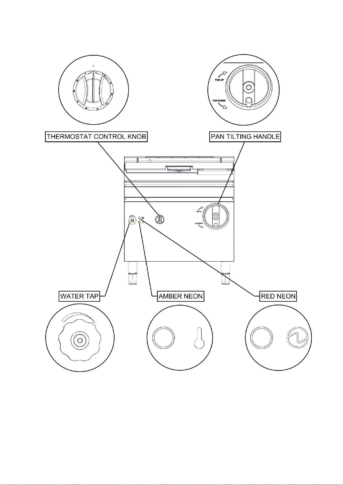
Controls
• OFF Position
Variable
temperature
setting
100°C - 300°C.
Turn handle
to lift pan up
and down.
Turn tap to turn
water ON and
OFF.
Indicates that
the heating
element is ON.
Indicates when
mains electricity
is ON.
Using the Bratt Pan
1. Ensure pan is fully lowered using the pan tilting handle.
7
Page 8
2. Turn mains electricity ON. The Red neon will illuminate.
3. Turn thermostat control knob to desired temperature. Amber neon will
illuminate.
4. When the desired temperature is reached, the Amber neon will go OFF.
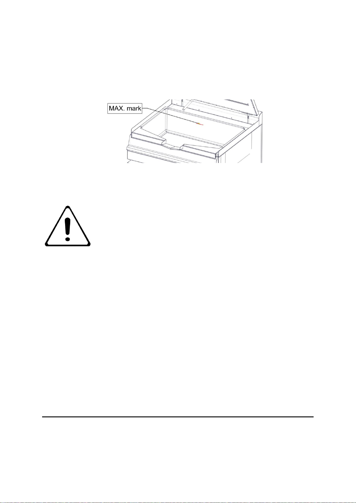
5. If cooking a liquid based food, ensure it does not go over the MAX mark as
shown below.
6. Turn ON the water tap to top up if necessary.
7. To empty the contents of the pan, first ensure the thermostat control knob is
turned OFF. Lift the pan with the pan tilting handle and the content will start
pouring out of the spout.
DO NOT DEEP FRY WITH THIS APPLIANCE.
GETTING THE MOST OUT OF THE APPLIANCE
SAVE ENERGY AND RUNNING COST BY TURNING OFF THE APPLIANCE WHEN NOT
IN USE.
8
Page 9

Griddling
Note that the centre of the pan is hotter than the edges when griddling.
Simmering and Stewing
Lid can be left slightly ajar if a gentle simmer is desired. As mentioned in griddling, the centre
of the pan is hotter so the content may tend to stick to the pan more around the middle.
CLEANING AND MAINTENANCE
All surfaces are easier to clean if spillage is removed before it becomes burnt on and if
appliance is cleaned daily.
CAUTION: Failure due to lack of proper cleaning is not covered by
warranty.
BEFORE ANY CLEANING IS UNDERTAKEN, ENSURE ISOLATING COCK IS TURNED
OFF AND CANNOT BE INADVERTENTLY TURNED ON.
WARNING – DO NOT ATTEMPT TO CLEAN THIS APPLIANCE WITH A JET OF WATER
OR STEAM CLEAN.
Clean pan as soon as possible after use with hot water and detergent. Soap filled steel wool
pads may be used to remove stubborn deposits. After cleaning, empty water from pan using
the pan tilting handle to lift the pan.
Do not use proprietary cleaners, especially those with a high caustic content on appliance
surfaces. This is particularly important when appliance is hot. Such cleaners can cause
serious damage or discolouration and only a soap or detergent solution should be used.
.
SPECIFICATION
9
Page 10

Model Number covered in this group of products
E3800
7.7
L1 11.2
L2 11.2
L3 11.2
TECHNICAL DATA - TABLE A
MODEL NUMBER
Current (A) at
230V
Total Power (kW)
E3800 800mm wide manual lift electric Bratt Pan
Technical Data
DIMENSIONS / ELECTRICAL CONNECTION LOCATIONS
INSTALLATION
10
Page 11

Unpacking
150mm from any combustible wall.
Well lit draught free area.
Level, Fireproof surface.
150mm
150mm
1. Remove all packaging from the appliance.
2. Remove all plastic coating that is on the appliance by peeling them off.
3. Ensure there are no missing parts to the appliance.
4. Ensure there are no damages to the appliance.
5. Fit Lid handle using fixings supplied, and locate water inlet pipe in position in the rear
flue at the left hand side.
Siting / Clearances
CAUTION: If suiting, the necessary clearances to any combustible wall
MUST BE the largest figure given for individual appliances instructions.
If a Gully is used in the premises, ensure it covers
the highlighted area.
11
Page 12

Electric Supply & Connection
Phase 1
Phase 2
Phase 3
Neutral
Earth
BROWN
BLACK
GREY
BLUE
GREEN/YELLOW
The location of the electrical connection is shown in “Dimensions/Electrical Connection
Location” Chapter. The appliance is suitable for AC supplies only. The standard terminal
arrangement is: 3 phase & neutral 5 wire connection (400V 3N~)
IF THE CABLE IS DAMAGED, IT MUST BE REPLACED BY A SUITABLY
QUALIFIED PERSON. A suitably rated isolating switch with contact
separation of at least 3mm in all poles must be installed and wiring executed
in accordance with relevant regulations. Access to mains terminal block is
gained by removing the control panel.
Water Supply
Connection to the water supply is via a ½” BSPP male threaded fitting at rear.
A threaded bush is supplied with the appliance to increase the size to ¾” (If required).
Water supply pressure should not exceed 500kPa (5 bar).
Assembly
1. Position appliance and carefully level using feet adjusters as shown below.
2. Appliances with castors should be fitted with accessories supplied according to
separate instructions provided.
3. Connect appliance to electric and water supply as stated in the previous section.
12
Page 13

Commissioning
NOTE: Prior to operation, ensure that ALL packing material has been removed. For
instructions on how to use the appliance, see ‘Operation’ chapter. For relevant figures,
please see ‘Technical Data’.
1. Turn appliance on and ensure Red Neon illuminates.
2. Turn water tap on and ensure it is working correctly without any leakage.
3. Empty water using the pan tilting handle to lift the pan up.
4. Lower the pan and turn thermostat control knob to 200°C. Ensure Amber neon
illuminates.
5. Wait till Amber neon turns OFF and measure the temperature at the middle of the
pan. Ensure it reaches around 220°C (±10°C).
6. Turn OFF appliance. Red neon should turn OFF.
If the appliance does not operate correctly please refer to the ‘Servicing’ section and rectify
the problem.
ENSURE THAT KITCHEN PERSONNEL UNDERSTAND THE CORRECT
OPERATION AND CLEANING OF APPLIANCE AND THAT SUCH
INDIVIDUALS ARE AWARE OF THE MAINS ISOLATING SWITCH
LOCATION.
PLEASE FILL OUT THE INFORMATION TABLE ON THE FRONT COVER
AFTER COMMISSIONING.
SERVICING
BEFORE ATTEMPTING ANY SERVICING, ENSURE ISOLATING COCK
IS TURNED OFF AND CANNOT BE INADVERTENTLY TURNED ON.
AFTER ANY MAINTENANCE TASK, CHECK APPLIANCE TO ENSURE
THAT IT PERFORMS CORRECTLY AND CARRY OUT ANY
NECESSARY ADJUSTMENTS AS DETAILED IN ‘COMMISSIONING’.
Symbols on drawings:
+ denotes a positive head screw requires to be removed.
– denotes a flat head screw requires to be removes.
denotes a nut or a hex head bolt requires to be removed.
13
Page 14

REMOVAL OF FRONT FASCIA / ACCESS TO ELECTRICS BOX
1 2 3
4
5 6
To gain access to the electrics box, first the front fascia must be removed.
14
Page 15

7
When removing the front fascia, care should be taken not to damage
the neon cables.
NEONS
Neons are attached to the front fascia. To replace them, remove the connections and the
nut.
15
Page 16

OPERTAING THERMOSTAT
1
2
The operating thermostat is located on the cover of the electrics box. To replace, remove the
clip that secures the thermostat capillary. Pull out thermostat phial then remove the two
screws on the cover of the electrics box..
When replacing the thermostat phial back into the hole, ensure that the
phial is pushed right back into the tube and reattach the Vidaflex.
16
Page 17

SAFETY THERMOSTAT
Safety thermostat is located on the left side of the electrics box. Push the button protruding
out from the bottom of the box to reset. To replace, remove the same clip that’s shown in the
operating thermostat. Pull out phial then remove the two screws.
When replacing the thermostat phial back into the hole, ensure that the phial is pushed right
back into the tube and reattach the Vidaflex.
TILT SWITCH
Tilt switch is located beside the electrics box.
17
Page 18

CONTACTOR
The contactors are located in the electrics box. To replace, lever it out by
using a flat headed screwdriver.
ELEMENTS
Lift Pan fully up to get access to the Element Box. To gain access to just the element
connections, remove the element connection cover a shown below.
18
Page 19

To replace the elements, first the element box must be removed as shown.
When replacing the bottom two elements, the thermostat tube must be removed as well.
They are all attached by hex nuts.
When replacing the Elements, ensure it is secured tightly to the pan base.
19
Page 20

Ensure Thermostat Tube is attached tightly to the Elements.
Wiring Diagram – 400V 3N~ Appliance
20
Page 21

21
Page 22

Wiring Diagram – 440V 3N~ Appliance
22
Page 23

FAULT FINDING
FAULT
POSSIBLE CAUSES
REMEDY
Red and Amber neon not
lighting.
No power from the supply.
Restore supply.
Blown fuse.
Replace fuse.
Faulty mains supply cord.
Replace supply cord.
Faulty Neons.
Replace Neons.
Amber neon not lighting but
Red neon is on.
Safety Thermostat tripped or
faulty.
Reset Thermostat. If faulty,
replace.
Operating Thermostat.
Check connections. If faulty,
replace.
Amber Neon.
Contactors.
Slow/Poor heating.
Operating Thermostat out of
calibration.
Replace Operating
thermostat.
Faulty Elements or
connections.
Check each connection to
the three elements. If any of
them are faulty, replace.
MAIN SPARES LIST
PART NAME
SPARES NUMBER
Red Neon
730962010
Amber Neon
730962040
Operating Thermostat
731910500 (S/S) 732150020 (DX)
Safety Thermostat
732150006
Tilt Switch
531750540
Contactor
734310440
Element
732150001
1A anti surge fuse
535420014
SPARE PARTS
When ordering spare parts please quote the following;
Appliance type
Serial number
This information will be found on data plate attached to base plate.
23
Page 24

SERVICE INFORMATION
In order to obtain maximum performance from this appliance we would recommend that a
maintenance contract be arranged with SERVICELINE. Visits may then be made at agreed
intervals to carry out adjustments and repairs. A quotation will be given upon request to the
contact number below:
SERVICELINE CONTACT:
Phone: 01438 363 000
Warranty Policy Shortlist
Warranty does not cover the following:-
• Correcting faults caused by incorrect installation of a product.
• Where an engineer cannot gain access to a site or a product.
• Repeat commission visits.
• Replacement of any parts where damage has been caused by misuse.
• Engineer waiting time will be chargeable.
• Routine maintenance and cleaning.
• Gas conversions i.e. Natural to Propane gas.
• Descaling of water products and cleaning of water sensors where softeners/ conditioners
are not fitted, or are fitted and not maintained.
• Blocked drains
• Independent steam generation systems.
• Gas, water and electrical supply external to appliance.
• Light bulbs
• Re-installing vacuum in kettle jackets.
• Replacement of grill burner ceramics when damage has been clearly caused by misuse.
• Where an engineer finds no fault with a product that has been reported faulty.
24
Page 25

• Re-setting or adjustment of thermostats when appliance is operating to specification.
• Cleaning and unblocking of fryer filter systems due to customer misuse.
• Lubrication and adjustment of door catches.
• Cleaning and Maintenance
• Cleaning of burner jets
• Poor combustion caused by lack of cleaning
• Lubrication of moving parts
• Lubrication of gas cocks
• Cleaning/adjustment of pilots
• Correction of gas pressure to appliance.
• Renewing of electric cable ends.
• Replacement of fuses
• Corrosion caused by use of chemical cleaners.
25
 Loading...