

Page 1
T100644 Ref. 3
E350/38 and E350/39
COUNTER TOP FRYERS
INSTALLATION and
SERVICING INSTRUCTIONS
IMPORTANT
The installer must ensure that the installation of the appliance is in conformity with these instructions and
National Regulations in force at the time of installation. Particular attention MUST be paid to -
BS7671 IEE Wiring Regulations
Health And Safety At Work Act.
Electricity At Work Regulations.
Fire Precautions Act
This appliance has been CE-marked on the basis of compliance with the Low Voltage and EMC Directives for
the voltages stated on the unit data plate.
WARNING - THIS APPLIANCE MUST BE EARTHED
On completion of the installation these instructions should be left with the Engineer-in-Charge for reference
during servicing. Further to this, The Users Instructions should be handed over to the User, having had a
demonstration of the operation and cleaning of the appliance.
IT IS MOST IMPORTANT THAT THESE INSTRUCTIONS BE CONSULTED BEFORE INSTALLING AND
COMMISSIONING THIS APPLIANCE. FAILURE TO COMPLY WITH THE SPECIFIED PROCEDURES MAY
RESULT IN DAMAGE OR THE NEED FOR A SERVICE CALL.
PREVENTATIVE MAINTENANCE CONTRACT
In order to obtain maximum performance from this unit we would recommend that a Maintenance Contract be
arranged with SERVICELINE. Visits may then be made at agreed intervals to carry out adjustments and
repairs. A quotation will be given upon request to the contact numbers below.
WEEE Directive Registration No. WEE/DC0059TT/PRO
At end of unit life, dispose of appliance and any replacement parts
in a safe manner, via a licenced waste handler.
Units are designed to be dismantled easily and recycling of all
material is encouraged whenever practicable.
Falcon Foodservice Equipment
HEAD OFFICE AND WORKS
Wallace View, Hillfoots Road, Stirling. FK9 5PY. Scotland.
SERVICELINE CONTACT -
PHONE - 01438 363 000 FAX - 01438 369 900
Page 2
Warranty Policy Shortlist
Warranty does not cover :-
Correcting faults caused by incorrect installation of a product.
Where an engineer cannot gain access to a site or a product.
Repeat commission visits.
Replacement of any parts where damage has been caused by misuse.
Engineer waiting time will be chargeable.
Routine maintenance and cleaning.
Gas conversions i.e. Natural to Propane gas.
Descaling of wat er products and cleaning of water sensors wher e softeners/conditioners are not fitted, or are
fitted and not maintained.
Blocked drains.
Independent steam generation systems.
Gas, water and electrical supply external to unit.
Light bulbs.
Re-installing vacuum in kettle jackets.
Replacement of grill burner ceramics when damage has been clearly caused by misuse.
Where an engineer finds no fault with a product that has been reported faulty.
Re-setting or adjustment of thermostats when unit is operating to specification.
Cleaning and unblocking of fryer filter systems due to customer misuse.
Lubrication and adjustment of door catches.
Cleaning and Maintenance
Cleaning of burner jets
Poor combustion caused by lack of cleaning
Lubrication of moving parts
Lubrication of gas cocks
Cleaning/adjustment of pilots
Correction of gas pressure to appliance.
Renewing of electric cable ends.
Replacement of fuses
Corrosion caused by use of chemical cleaners.
Page 3
SECTION 1 - INSTALLATION
1.2 SITING
The appliance must be installed on a firm counter or
table or alternatively on a special purpose built stand
supplied by Falcon. The unit may be installed to
within 25mm of any wall or partition at the rear and
sides.
A vertical clearance of 900mm between the top of the
unit and any overlying combustible surface must be
provided and Fire Regulations must be complied with.
1.3 ELECTRICAL SUPPLY
The fryers are equipped with a single cable entry
situated at the rear, suitable for a 20mm conduit
connection.
A suitably rated isolating switch with contact
separation of at least 3mm in all poles must be
installed and all wiring executed in accordance with
the regulations listed on the title page of this man ual.
THESE APPLIANCES MUST BE EARTHED.
An earth terminal is located within the terminal
compartment for this purpose.
1.4 ELECTRICAL RATINGS
The fryers are for use on AC supplies only. Either 3
phase/ 4 wire or single phase supplies can be used.
The electrical loadings are stated on the appliance
data plate.
SECTION 2 - ASSEMBLY and
COMMISSIONING
2.1 ASSEMBLY
a) Remove feet from bag and screw into locations on
unit base prior to positioning.
b) Position appliance and carefully level it. Use feet
adjusters when mounting on a counter or table.
To mount a unit on purpose built stand, refer to
instructions supplied with stand.
c) The appliance is supplied complete and ready to
connect to the mains supply.
2.2 CONNECTION TO THE ELECTRICAL SUPPLY
To gain access to terminals proceed as follows:
Remove knob at drain valve lever end. Use a 6mm
spanner on lever and a 10mm spanner on knob.
Remove two fixings in upper flange panel, i.e. below
front hob.
Move panel slightly forward at top until it clears hob.
Lift panel slightly upward thus releasing lower fixing
and remove panel.
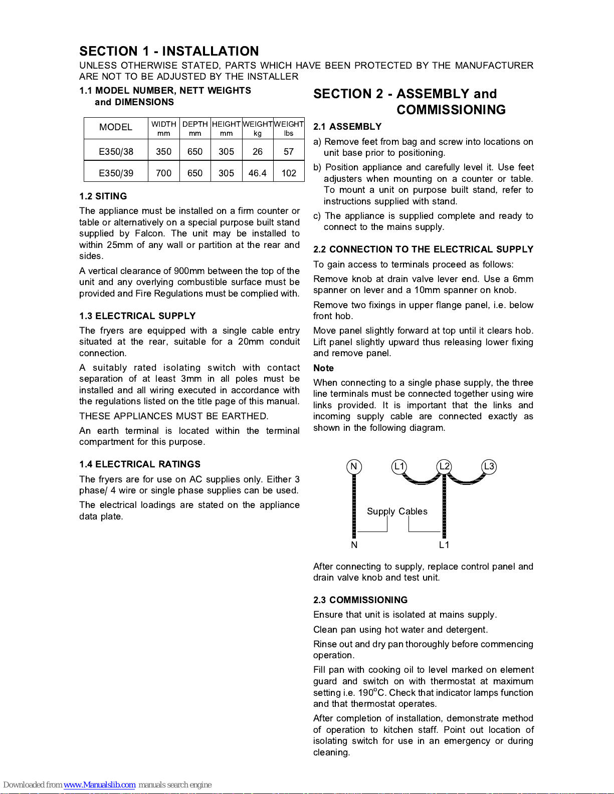
Note
When connecting to a single phase supply, the three
line terminals must be connected together using wire
links provided. It is important that the links and
incoming supply cable are connected exactly as
shown in the following diagram.
After connecting to supply, replace control panel and
drain valve knob and test unit.
2.3 COMMISSIONING
Ensure that unit is isolated at mains supply.
Clean pan using hot water and detergent.
Rinse out and dry pan thoroughly before commencing
operation.
Fill pan with cooking oil to level marked on element
guard and switch on with thermostat at maximum
setting i.e. 190
o
C. Check that indicator lamps function
and that thermostat operates.
After completion of installation, demonstrate method
of operation to kitchen staff. Point out location of
isolating switch for use in an emergency or during
cleaning.
UNLESS OTHERWISE STATED, PARTS WHICH HAVE BEEN PROTECTED BY THE MANUFACTURER
ARE NOT TO BE ADJUSTED BY THE INSTALLER
MODEL
WIDTHmmDEPTHmmHEIGHTmmWEIGHTkgWEIGHT
lbs
E350/38 350 650 305 26 57
E350/39 700 650 305 46.4 102
1.1 MODEL NUMBER, NETT WEIGHTS
and DIMENSIONS
NL1L2L3
Supply Cables
NL1
Page 4

SECTION 3 - SERVICING
BEFORE ATTEMPTING ANY MAINTENANCE,
ISOLATE THE APPLIANCE AT THE MAIN SWITCH
AND TAKE STEPS TO ENSURE THAT IT IS NOT
INADVERTENTLY SWITCHED ON.
3.1 CONTROL PANEL - TO REMOVE
a) Drain pan by inserting drain pipe over a suitable
receptacle then pull out drain lever and move it to
the right.
b) Remove knob at drain valve lever end using a 6mm
spanner on lever and a 10mm spanner on knob.
c) Remove two screws in upper flange of facia panel
i.e. below front hob.
d) Move panel slightly forward at top until clear of hob
then lift panel slightly upward thus releasing lower
fixing and to remove panel.
3.2 CONTROL THERMOSTAT
and INDICATOR LAMPS
If these prove faulty they are not normally repairable
and must be replaced using the following procedures:
3.2.1 Control Thermostat
In order to replace control thermostat, it will be
necessary to remove unit from stand or table location.
Adopt the following procedure :
a) Drain pan(s).
b) Remove control panel as detailed in Section 3.1.
c) Note positions and remove wires.
d) Using a 'stubby' pozi screwdriver, remove
thermostat from control panel.
e) Disconnect supply connections and remove fryer
from location to enable it to be turned on its side
later.
f) Remove element as detailed in Section 3.3.
g) Remove cover plate from element hinge block
through which thermostat capillary tube passes.
Manoeuvre tube and phial through moving hinge
tube.
h) From front, remove two fixings which secure base
plate and remove plate.
j) Turn unit on to its side. Feed capillary tube and
phial through hole in base of hinge block and
remove thermostat.
k) Replace in reverse order. Take care that capillary
tube is well clear of element terminals.
m) Replace elements (see Section 3.3). Also replace
base and control panels.
n) Fill pan with oil and heat it up.
Carry out installation tests.
Note
When replacing a cotrol thermostat, fit existing
insulating sleeving over capillary tubing. Ensure that
no portion of tubing is exposed to possible contact
with live parts. Coil excess tube by wrapping it around
a suitable mandrel of approximately 25mm diameter.
3.2.2 Indicator Lamps
Remove control panel as detailed in Section 3.1.
Pull off lamp connections and undo nut that secures it
at rear. Remove lamp and replace in reverse order.
3.3 ELEMENT
To replace heating element proceed as follows:
a) Drain pan.
b) Remove basket support bar from element and fully
raise element.
c) Remove 10 pozidriv screws in underside of
element terminal box.
d) Remove element terminal box bottom cover plate.
This can be effected by prising up lower edge with
a screwdriver.
e) Lower element and remove element guard (4
screws). Also undo clips that secure thermostat
phial to element assembly.
f) Remove push-on element connections, first noting
their locations.
g) Remove two hex-headed screws which secure
element assembly to terminal box. Remove
element, taking care not to kink or otherwise
damage thermostat capillary tube.
Replace element in reverse order ensuring that oil
resistant gasket is fitted under element mounting
plate.
Note that thermostat phial is fitted in third hairpin of
element from left, clamps being applied to centres
of three element sheaths.
3.4 SAFETY THERMOSTAT
3.4.1 To Reset
In the event of a control thermostat failure that results
in overheating of oil, safety thermostat will interrupt
and switch off all power to elements.
To re-establish circuit, it will be necessary to reset
safety thermostat.
First allow fryer to cool, then remove control panel as
detailed in Section 3.1.
On single pan fryer (E350/38), safety thermostat is
reset by depressing tubular rod situated immediately
below drain valve.
In the case of the double pan fryer (E350/39), two
safety thermostats are located at rear of unit between
two pans.
Reach in and depress red reset button (left and right
thermostats appropriate to left and right pans).
Page 5

3.4.2 To Replace
In order to replace safety thermostat it will be
necessary to remove unit from its location on stand
or table. Adopt the following procedure:
a) Drain pan.
b) Remove control panel as detailed in Section 3.1.
c) Disconnect supply connections and remove unit
from its location to enable it to be turned on its
side later.
d) Remove element as detailed in Section 3.3.
e) Remove cover plate on element hinge block
through which capillary tube passes. Manoeuvre
capillary tube and phial through moving hinge
tube.
f) From front, remove two fixings that secure the
base plate and remove the plate.
g) Turn the appliance on to its side and remove
safety thermostat from mounting bracket. Pull off
connections.
h) Feed capillary tube and phial through hole in base
of hinge block and remove the thermostat.
j) Replace thermostat in reverse order, taking care
that capillary tube is well clear of element
terminals.
k) Replace elements (see Section 3.3). Also replace
base panel and the control panel.
m) Fill pan with oil and heat it up. Carry out installation
tests.
3.5 DRAIN VALVE - TO REMOVE
Drain pan.
Remove control panel as detailed in Section 3.1.
Undo compression fitting nut at rear of valve,
adjacent to pan (turn it clockwise).
Remove saddle clamp at front and remove valve.
Fit a new valve in reverse order. Apply a small
quantity of high melting point grease to sliding parts of
operating lever and also to circular shaped plate on
which end of spindle runs.
3.6 TILT SWITCH
Located in element terminal box, this component
should require no maintenance.
Page 6

E350/38 Fryer Wiring Diagram
Page 7

E350/39 Fryer Wiring Diagram
 Loading...