

Page 1
RZZ 210 Ref.1
E350/34 and E350/35
GRIDDLE TOPS
INSTALLATION and
SERVICING INSTRUCTIONS
IMPORTANT
The installer must ensure that the installation of the appliance is in conformity with these instructions and
National Regulations in force at the time of installation. Particular attention MUST be paid to -
BS7671 IEE Wiring Regulations
Electricity at Work Regulations
Health And Safety At Work Act
Fire Precautions Act
This appliance has been CE-marked on the basis of compliance with the Low Voltage and EMC Directives for
the voltages stated on the Data Plate
WARNING -THIS APPLIANCE MUST BE EARTHED
On completion of the installation these instructions should be left with the Engineer-in-Charge for reference
during servicing. Further to this, The Users Instructions should be handed over to the User, having had a
demonstration of the operation and cleaning of the appliance.
IT IS MOST IMPORTANT THAT THESE INSTRUCTIONS BE CONSULTED BEFORE INSTALLING AND
COMMISSIONING THIS APPLIANCE. FAILURE TO COMPLY WITH THE SPECIFIED PROCEDURES MAY
RESULT IN DAMAGE OR THE NEED FOR A SERVICE CALL.
PREVENTATIVE MAINTENANCE CONTRACT
In order to obtain maximum performance from this unit we would recommend that a Maintenance Contract be
arranged with AFE SERVICE. Visits may then be made at agreed intervals to carry out adjustments and
repairs. A quotation will be given upon request to the contact numbers below.
Falcon Foodservice Equipment
HEAD OFFICE AND WORKS
PO Box 37, Foundry Loan, Larbert.
Stirlingshire. Scotland. FK5 4PL
AFE SERVICE CONTACT -
PHONE - 01438 751 111 FAX - 01438 369 900
Page 2
SECTION 1 - INSTALLATION
1.2 SITING
The appliance should be installed on a table, counter,
or similar surface. Alternatively it can be mounted on
the purpose designed floor stand supplied by Falcon.
Should it require to be positioned in close proximity to
a wall, partition, etc., a minimum clearance of 25mm
at the reae and sides is recommended.
A vertical clearance between the the plate and any
overlying combustible surface of 900mm should be
allowed. Fire Regulations must be complied with.
1.3 ELECTRICAL SUPPLY
These units are designed for use on AC supplies
only. The E350/34 Griddle plate is for use on single
phase supplies only. The E350/35 model can be used
on single-phase or alternatively on a 2-phase supply.
1.3.1 Supply Connection
The cable entry is located at the rear of the appliance
and is suitable for 20mm conduit. A suitable isolating
switch must be provided with a minimum contact
separation of 3 mm in all poles. All wiring must be
executed in accordance with the regulations listed on
the cover of the manual.
These appliances must be earthed.
A suitable terminal is provided for this purpose and
must be used for this purpose.
Note
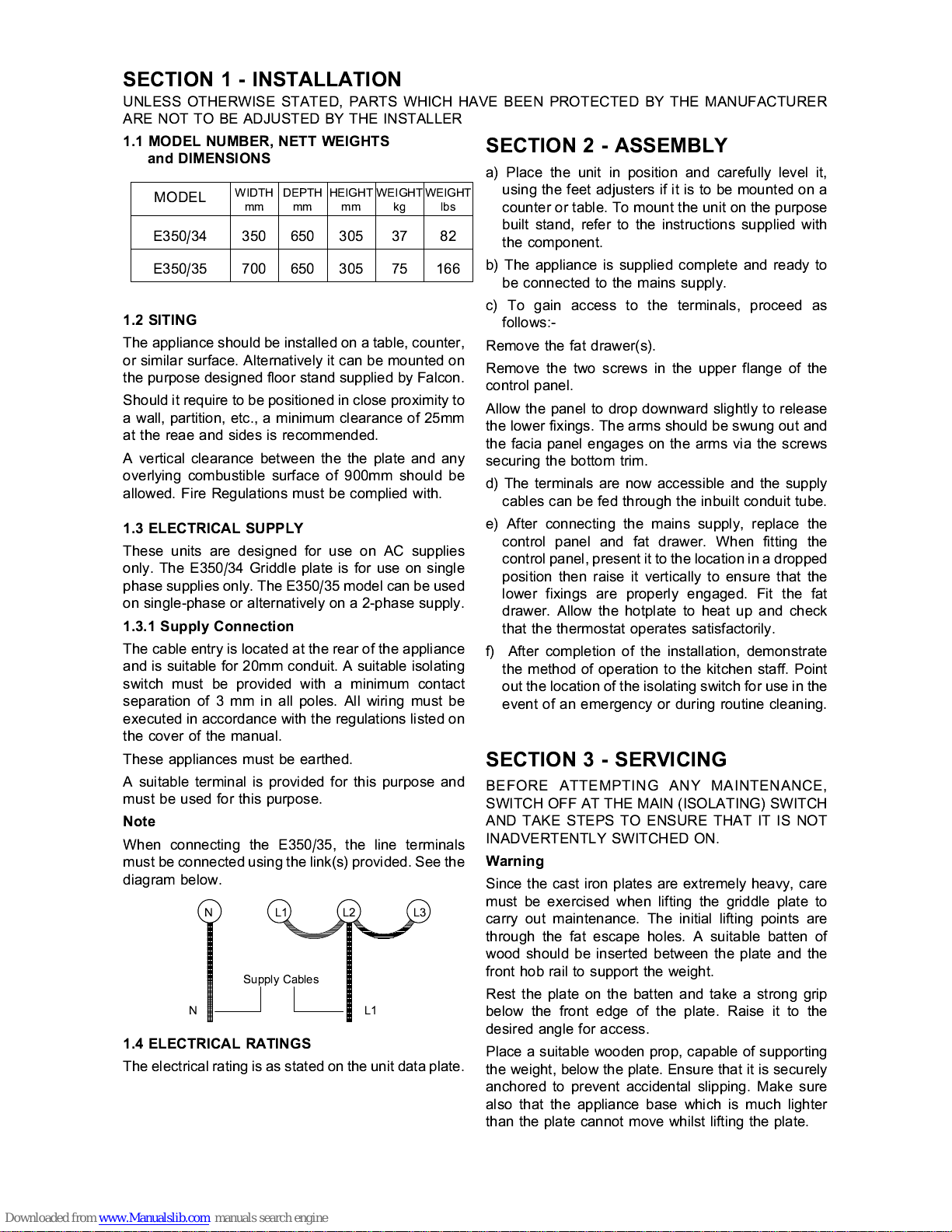
When connecting the E350/35, the line terminals
must be connected using the link(s) provi ded. See the
diagram below.
NL1L2L3
Supply Cables
NL1
1.4 ELECTRICAL RATINGS
The electrical rating is as stated on the unit data plate.
SECTION 2 - ASSEMBLY
a) Place the unit in position and carefully level it,
using the feet adjusters if it is to be mounted on a
counter or table. To mount the unit on the purpose
built stand, refer to the instructions supplied with
the component.
b) The appliance is supplied complete and ready to
be connected to the mains supply.
c) To gain access to the terminals, proceed as
follows:-
Remove the fat drawer(s).
Remove the two screws in the upper flange of the
control panel.
Allow the panel to drop downward slightly to release
the lower fixings. The arms should be swung out and
the facia panel engages on the arms via the screws
securing the bottom trim.
d) The terminals are now accessible and the supply
cables can be fed through the inbuilt conduit tube.
e) After connecting the mains supply, replace the
control panel and fat drawer. When fitting the
control panel, present it to the location in a dropped
position then raise it vertically to ensure that the
lower fixings are properly engaged. Fit the fat
drawer. Allow the hotplate to heat up and check
that the thermostat operates satisfactorily.
f) After completion of the installation, demonstrate
the method of operation to the kitchen staff. Point
out the location of the isolating switch for use in the
event of an emergency or during routine cleaning.
SECTION 3 - SERVICING
BEFORE ATTEMPTING ANY MAINTENANCE,
SWITCH OFF AT THE MAIN (ISOLATING) SWITCH
AND TAKE STEPS TO ENSURE THAT IT IS NOT
INADVERTENTLY SWITCHED ON.
Warning
Since the cast iron plates are extremely heavy, care
must be exercised when lifting the griddle plate to
carry out maintenance. The initial lifting points are
through the fat escape holes. A suitable batten of
wood should be inserted between the plate and the
front hob rail to support the weight.
Rest the plate on the batten and take a strong grip
below the front edge of the plate. Raise it to the
desired angle for access.
Place a suitable wooden prop, capable of supporting
the weight, below the plate. Ensure that it is securely
anchored to prevent accidental slipping. Make sure
also that the appliance base which is much lighter
than the plate cannot move whilst lifting the plate.
UNLESS OTHERWISE STATED, PARTS WHICH HAVE BEEN PROTECTED BY THE MANUFACTURER
ARE NOT TO BE ADJUSTED BY THE INSTALLER
MODEL
WIDTHmmDEPTHmmHEIGHTmmWEIGHTkgWEIGHT
lbs
E350/34 350 650 305 37 82
E350/35 700 650 305 75 166
1.1 MODEL NUMBER, NETT WEIGHTS
and DIMENSIONS
Page 3

When ordering spares, please quote the model
number, serial number and voltage, as stated on
the data plate.
3.1 CONTROL PANEL - To Remove
Remove the fat drawer, located below the control
panel.
Remove the two screws in the upper flange of the
facia panel.
Allow the panel to drop downward slightly to release
the lower fixings. Remove the panel.
Replace in reverse order.
3.2 THERMOSTAT - To Replace
Remove the control panel as detailed in Sectuon 3.1.
In the controls compartment top there are a number
of hex head screws which hold the plate in position, 2
on the E350/34 and 4 on the E350/35. Remove these
and raise the plate from the front. Prop it up with a
suitable piece of wood. Take care not to strain the
thermostat capillary tube.
Undo the two screws which secure the thermostat
phial clamping plate and release the phial.
Pull off the connections to the thermostat, noting their
locations according to the numbers on the wires. Pull
off the thermostat knob and remove the two screws
below to release the thermostat from the panel.
Feed the capillary tube and phial forward through the
rear of the control compartment and remove the
assembly.
Replace in reverse order, taking care to fit the
insulating sleeving over the capillary before fitting
the thermostat.
Ensure that the earth bonding connection is replaced
behind the thermostat fixing lug. After fitting the
thermostat, test the unit using a low setting and check
that the amber light goes out as the thermostat
opens.
Pull off the connections to the thermostat, noting their
locations.
3.3 PILOT LAMPS - To Replace
a) Remove control panel as detailed in Section 3.1.
b) Pull off the lamp connections.
c) Remove the nut securing the lamp at the rear and
remove the lamp.
3.4. HEATING ELEMENTS - To Replace
a) Remove control panel as detailed in Section 3.1.
b) Prop up the hotplate as described in Section 3.2.
c) Remove the element connections.
d) Remove the nuts fixing the element lagging boxes.
e) Remove the clamping plates securing the element.
When fitting a new element, ensure that it is properly
fixed to the underside of the hotplate, located by the
various projections cast into the plate.
Ensure that the element earthing connections are
exactly as they were before replacing the element.
Page 4

E350/35 GRIDDLE PLATE - WIRING DIAGRAM (Drawing No. BW32471/B)
E350/34 GRIDDLE PLATE - WIRING DIAGRAM (Drawing No. AW32470/B)
 Loading...