

Page 1

RZZ 209 Ref.1
E350/30
FOUR HOTPLATE RANGE
INSTALLATION and
SERVICING INSTRUCTIONS
IMPORTANT
The installer must ensure that the installation of the appliance is in conformity with these instructions and
National Regulations in force at the time of installation. Particular attention MUST be paid to -
BS7671 IEE Wiring Regulations
Electricity at Work Regulations
Health And Safety At Work Act
Fire Precautions Act
This appliance has been CE-marked on the basis of compliance with the Low Voltage and EMC Directives for
the voltages stated on the Data Plate
WARNING -THIS APPLIANCE MUST BE EARTHED
On completion of the installation these instructions should be left with the Engineer-in-Charge for reference
during servicing. Further to this, The Users Instructions should be handed over to the User, having had a
demonstration of the operation and cleaning of the appliance.
IT IS MOST IMPORTANT THAT THESE INSTRUCTIONS BE CONSULTED BEFORE INSTALLING AND
COMMISSIONING THIS APPLIANCE. FAILURE TO COMPLY WITH THE SPECIFIED PROCEDURES MAY
RESULT IN DAMAGE OR THE NEED FOR A SERVICE CALL.
PREVENTATIVE MAINTENANCE CONTRACT
In order to obtain maximum performance from this unit we would recommend that a Maintenance Contract be
arranged with AFE SERVICE. Visits may then be made at agreed intervals to carry out adjustments and
repairs. A quotation will be given upon request to contact numbers below.
Falcon Foodservice Equipment
HEAD OFFICE AND WORKS
PO Box 37, Foundry Loan, Larbert.
Stirlingshire. Scotland. FK5 4PL
SERVICE LINE CONTACT -
PHONE - 01438 751 111 FAX - 01438 369 900
Page 2
SECTION 1 - INSTALLATION
1.2 SITING
The appliance should be installed on a firm level floor
in a well lit position. Should the unit be required to be
positioned in close proximity to a wall, partition or
decorative finish, etc. the surface must be
constructed of non-combustible material.
Alternatively it may be clad in a suitable
non-combustible insulating material. Close attention
should be paid to Fire Regulations.
1.3 ELECTRICAL SUPPLY
The appliance is designed for use on AC supplies
only and can be operated on either a 3 phase/4 wire
AC supply or a single phase AC supply by using the
bridging links supplied.
Warning
This appliance must be earthed. (An earth terminal is
provided).
The connection to the mains electric supply must be
made through a suitable isolating switch with a
contact separation of at least 3mm in all poles.
Wiring should conform to I.E.E. regulations and the
installation should satisfy the local supply authority.
1.4 ELECTRICAL RATINGS
The electrical rating is as stated on unit data plate.
Note
The hotplates embody a temperature limiting device.
This automatically cuts off part of the element circuit
should the plate become overheated due to being left
switched on without a pot on it.
SECTION 2 - ASSEMBLY
a) Place the appliance in position and carefully level it
by turning the feet adjusters. Holes are provided in
the feet to enable the appliance to be fixed to the
floor if this is considered necessary.
b) Open the door and remove all packing material etc.
c) Connect the unit to the electrical supply (terminals
underneath).
Note
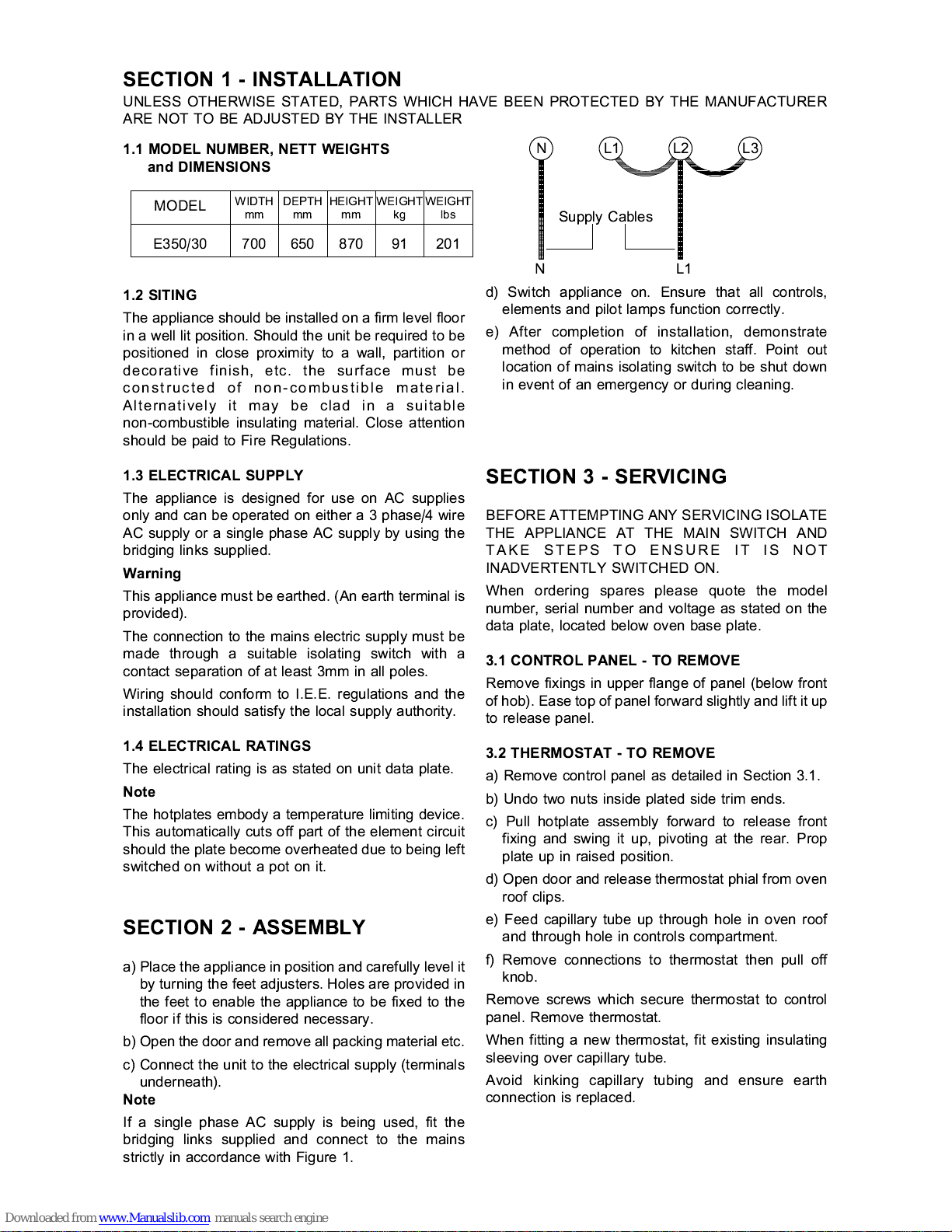
If a single phase AC supply is being used, fit the
bridging links supplied and connect to the mains
strictly in accordance with Figure 1.
NL1L2L3
Supply Cables
NL1
d) Switch appliance on. Ensure that all controls,
elements and pilot lamps function correctly.
e) After completion of installation, demonstrate
method of operation to kitchen staff. Point out
location of mains isolating switch to be shut down
in event of an emergency or during cleaning.
SECTION 3 - SERVICING
BEFORE ATTEMPTING ANY SERVICING ISOLATE
THE APPLIANCE AT THE MAIN SWITCH AND
TAKE STEPS TO ENSURE IT IS NOT
INADVERTENTLY SWITCHED ON.
When ordering spares please quote the model
number, serial number and voltage as stated on the
data plate, located below oven base plate.
3.1 CONTROL PANEL - TO REMOVE
Remove fixings in upper flange of panel (below front
of hob). Ease top of panel forward slightly and lift it up
to release panel.
3.2 THERMOSTAT - TO REMOVE
a) Remove control panel as detailed in Section 3.1.
b) Undo two nuts inside plated side trim ends.
c) Pull hotplate assembly forward to release front
fixing and swing it up, pivoting at the rear. Prop
plate up in raised position.
d) Open door and release thermostat phial from oven
roof clips.
e) Feed capillary tube up through hole in oven roof
and through hole in controls compartment.
f) Remove connections to thermostat then pull off
knob.
Remove screws which secure thermostat to control
panel. Remove thermostat.
When fitting a new thermostat, fit existing insulating
sleeving over capillary tube.
Avoid kinking capillary tubing and ensure earth
connection is replaced.
UNLESS OTHERWISE STATED, PARTS WHICH HAVE BEEN PROTECTED BY THE MANUFACTURER
ARE NOT TO BE ADJUSTED BY THE INSTALLER
MODEL
WIDTHmmDEPTHmmHEIGHTmmWEIGHTkgWEIGHT
lbs
E350/30 700 650 870 91 201
1.1 MODEL NUMBER, NETT WEIGHTS
and DIMENSIONS
Page 3

3.3 HOTPLATES - TO REMOVE
a) Remove facia panel as detailed in Section 3.1 and
raise hotplate assembly as detailed in Section 3.2.
b) Remove hotplate connections and undo central
fixing nut. This will allow hotplate to be removed
from top.
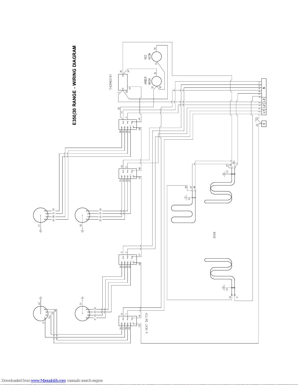
Fit replacement plate in reverse order, referring to
wiring diagram when re-connecting.
3.4 CONTROL SWITCHES - TO REMOVE
a) Remove control panel as detailed in Section 3.1.
b)Remove switch conn ections, note cable
arrangement.
c) Pull off control knob and undo fixing screws to
release switch. Fit new switch in reverse order,
ensure that earth bonding wire is attached to it.
3.5 PILOT LAMPS - TO REMOVE
a) Remove control panel as detailed in Section 3.1.
b) Pull off connections to lamp.
c) Remove nut at panel rear to release lamp. Fit
replacement in reverse order.
3.6 OVEN ELEMENTS - TO REMOVE
a) Remove control panel as detailed in Section 3.1.
b) Remove outer side panels as follows. Undo
screws in rear flange of panel. Swing panel rear
outward slightly then forward to release front fixing.
c) Open door and remove base panel.
d) Remove element connections and undo fixing nut.
e) Withdraw element from inside oven. Replace
element in reverse order, ensu ring small earth
bonding wire connection is securely fastened in
place.
Page 4
431
2
5
P2
P1
P3
431
2
5
P2
P1
P3
431
2
5
P2
P1
P3
431
2
5
P2
P1
P3
E350/30 RANGE - WIRING DIAGRAM
 Loading...