

Page 1
E2962, E2994,
Manual-tilt Bratt Pans
E2965 and E2995
Auto-tilt Bratt Pans
INSTALLATION and
SERVICING INSTRUCTIONS
IMPORTANT
The installer must ensure that the installation of the appliance is in conformity with these instructions and
National Regulations in force at the time of installation. Particular attention MUST be paid to -
BS7671 IEE Wiring Regulations
Electricity at Work Regulations
Health And Safety At Work Act
Fire Precautions Act
This appliance has been CE-marked on the basis of compliance with the Low Voltage and EMC Directives for
the voltages stated on the Data Plate
WARNING -THIS APPLIANCE MUST BE EARTHED
On completion of the installation these instructions should be left with the Engineer-in-Charge for reference
during servicing. Further to this, The Users Instructions should be handed over to the User, having had a
demonstration of the operation and cleaning of the appliance.
IT IS MOST IMPORTANT THAT THESE INSTRUCTIONS BE CONSULTED BEFORE INSTALLING AND
COMMISSIONING THIS APPLIANCE. FAILURE TO COMPLY WITH THE SPECIFIED PROCEDURES MAY
RESULT IN DAMAGE OR THE NEED FOR A SERVICE CALL.
PREVENTATIVE MAINTENANCE CONTRACT
In order to obtain maximum performance from this unit we would recommend that a Maintenance Contract be
arranged with SERVICELINE. Visits may then be made at agreed intervals to carry out adjustments and
repairs. A quotation will be given upon request to the contact numbers below.
WEEE Directive Registration No. WEE/DC0059TT/PRO
At end of unit life, dispose of appliance and any replacement parts
in a safe manner, via a licenced waste handler.
Units are designed to be dismantled easily and recycling of all
material is encouraged whenever practicable.
Falcon Foodservice Equipment
HEAD OFFICE AND WORKS
Wallace View, Hillfoots Road, Stirling. FK9 5PY. Scotland
SERVICELINE CONTACT -
PHONE - 01438 363 000 FAX - 01438 369 900
T100724 Ref. 3
Page 2
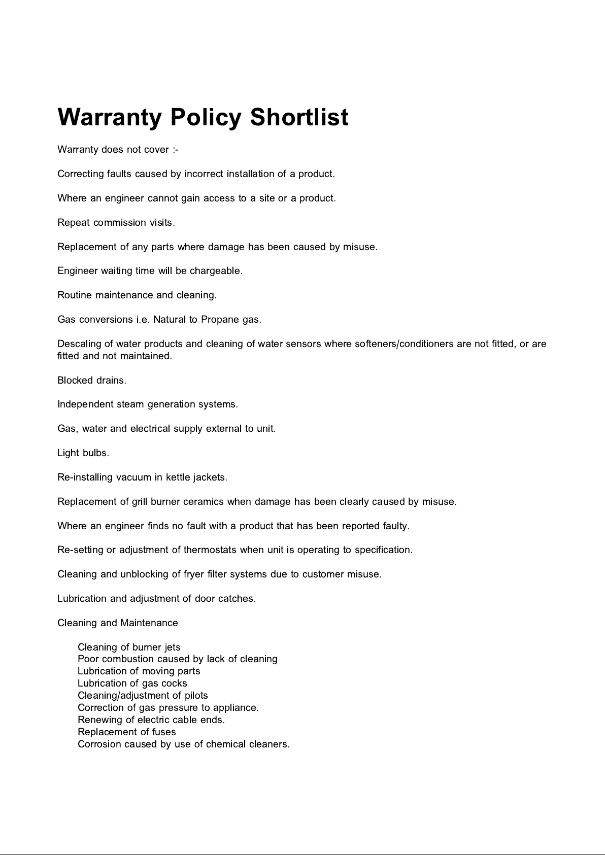
Warranty Policy Shortlist
Warranty does not cover :-
Correcting faults caused by incorrect installation of a product.
Where an engineer cannot gain access to a site or a product.
Repeat commission visits.
Replacement of any parts where damage has been caused by misuse.
Engineer waiting time will be chargeable.
Routine maintenance and cleaning.
Gas conversions i.e. Natural to Propane gas.
Descaling of water products and cleaning of water sensors where softeners/conditioners are not fitted, or are
fitted and not maintained.
Blocked drains.
Independent steam generation systems.
Gas, water and electrical supply external to unit.
Light bulbs.
Re-installing vacuum in kettle jackets.
Replacement of grill burner ceramics when damage has been clearly caused by misuse.
Where an engineer finds no fault with a product that has been reported faulty.
Re-setting or adjustment of thermostats when unit is operating to specification.
Cleaning and unblocking of fryer filter systems due to customer misuse.
Lubrication and adjustment of door catches.
Cleaning and Maintenance
Cleaning of burner jets
Poor combustion caused by lack of cleaning
Lubrication of moving parts
Lubrication of gas cocks
Cleaning/adjustment of pilots
Correction of gas pressure to appliance.
Renewing of electric cable ends.
Replacement of fuses
Corrosion caused by use of chemical cleaners.
Page 3
SECTION 1 - INSTALLATION
UNLESS OTHERWISE STATED, PARTS WHICH HAVE BEEN PROTECTED BY THE MANUFACTURER
ARE NOT TO BE ADJUSTED BY THE INSTALLER
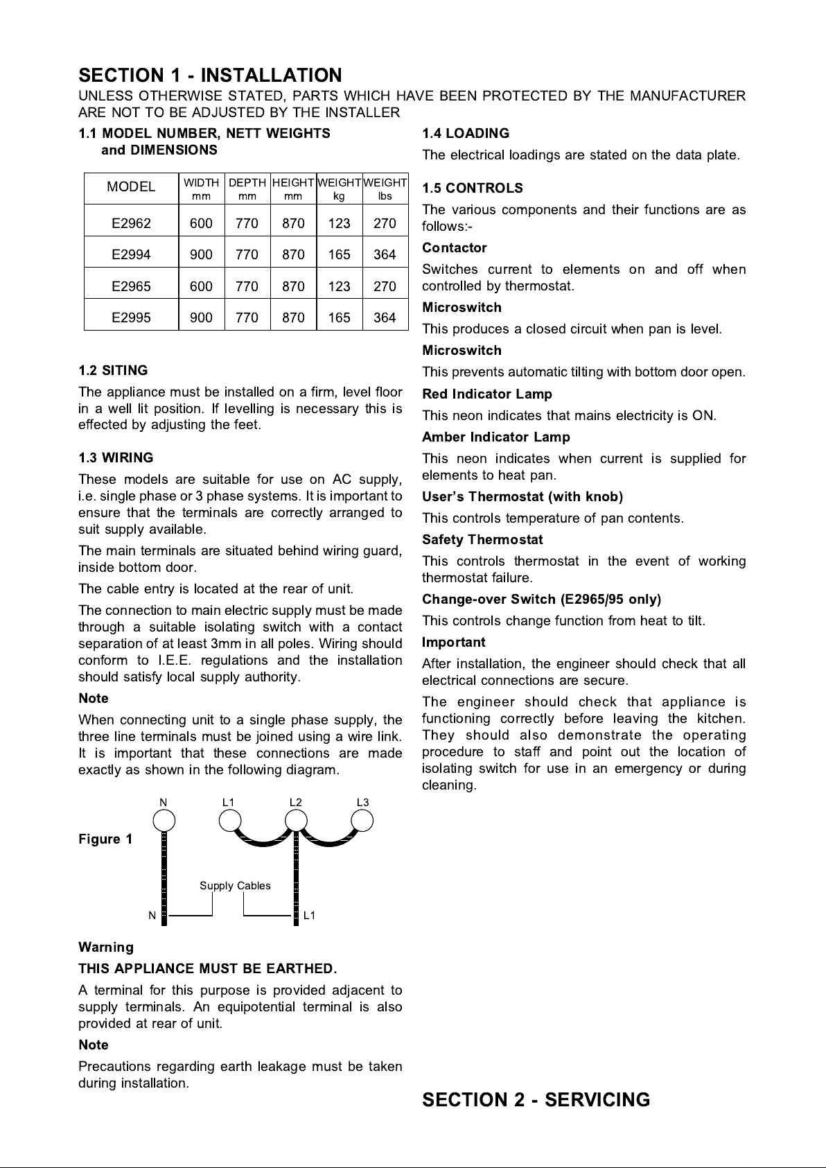
1.1 MODEL NUMBER, NETT WEIGHTS
and DIMENSIONS
1.4 LOADING
The electrical loadings are stated on the data plate.
MODEL
WIDTHmmDEPTHmmHEIGHTmmWEIGHTkgWEIGHT
lbs
E2962 600 770 870 123 270
E2994 900 770 870 165 364
E2965 600 770 870 123 270
E2995 900 770 870 165 364
1.2 SITING
The appliance must be installed on a firm, level floor
in a well lit position. If levelling is necessary this is
effected by adjusting the feet.
1.3 WIRING
These models are suitable for use on AC supply,
i.e. single phase or 3 phase systems. It is important to
ensure that the terminals are correctly arranged to
suit supply available.
The main terminals are situated behind wiring guard,
inside bottom door.
The cable entry is located at the rear of unit.
The connection to main electric supply must be made
through a suitable isolating switch with a contact
separation of at least 3mm in all poles. Wiring should
conform to I.E.E. regulations and the installation
should satisfy local supply authority.
Note
When connecting unit to a single phase supply, the
three line terminals must be joined using a wire link.
It is important that these connections are made
exactly as shown in the following diagram.
NL1L2L3
1.5 CONTROLS
The various components and their functions are as
follows:-
Contactor
Switches current to elements on and off when
controlled by thermostat.
Microswitch
This produces a closed circuit when pan is level.
Microswitch
This prevents automatic tilting with bottom door open.
Red Indicator Lamp
This neon indicates that mains electricity is ON.
Amber Indicator Lamp
This neon indicates when current is supplied for
elements to heat pan.
User's Thermostat (with knob)
This controls temperature of pan contents.
Safety Thermostat
This controls thermostat in the event of working
thermostat failure.
Change-over Switch (E2965/95 only)
This controls change function from heat to tilt.
Important
After installation, the engineer should check that all
electrical connections are secure.
The engineer should check that appliance is
functioning correctly before leaving the kitchen.
They should also demonstrate the operating
procedure to staff and point out the location of
isolating switch for use in an emergency or during
cleaning.
Figure 1
Supply Cables
NL1
Warning
THIS APPLIANCE MUST BE EARTHED.
A terminal for this purpose is provided adjacent to
supply terminals. An equipotential terminal is also
provided at rear of unit.
Note
Precautions regarding earth leakage must be taken
during installation.
SECTION 2 - SERVICING
Page 4
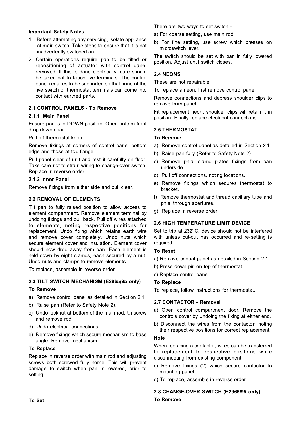
Important Safety Notes
1. Before attempting any servicing, isolate appliance
at main switch. Take steps to ensure that it is not
inadvertently switched on.
2. Certain operations require pan to be tilted or
repositioning of actuator with control panel
removed. If this is done electrically, care should
be taken not to touch live terminals. The control
panel requires to be supported so that none of the
live switch or thermostat terminals can come into
contact with earthed parts.
2.1 CONTROL PANELS - To Remove
2.1.1 Main Panel
Ensure pan is in DOWN position. Open bottom front
drop-down door.
Pull off thermostat knob.
Remove fixings at corners of control panel bottom
edge and those at top flange.
Pull panel clear of unit and rest it carefully on floor.
Take care not to strain wiring to change-over switch.
Replace in reverse order.
2.1.2 Inner Panel
Remove fixings from either side and pull clear.
2.2 REMOVAL OF ELEMENTS
Tilt pan to fully raised position to allow access to
element compartment. Remove element terminal by
undoing fixings and pull back. Pull off wires attached
to elements, noting respective positions for
replacement. Undo fixing which retains earth wire
and remove cover completely. Undo nuts which
secure element cover and insulation. Element cover
should now drop away from pan. Each element is
held down by eight clamps, each secured by a nut.
Undo nuts and clamps to remove elements.
To replace, assemble in reverse order.
2.3 TILT SWITCH MECHANISM (E2965/95 only)
To Remove
a) Remove control panel as detailed in Section 2.1.
b) Raise pan (Refer to Safety Note 2).
c) Undo locknut at bottom of the main rod. Unscrew
and remove rod.
d) Undo electrical connections.
e) Remove fixings which secu re mechanism to base
angle. Remove mechanism.
To Replace
Replace in reverse order with main rod and adjusting
screws both screwed fully home. This will prevent
damage to switch when pan is lowered, prior to
setting.
There are two ways to set switch -
a) For coarse setting, use main rod.
b) For fine setting, use screw which presses on
microswitch lever.
The switch should be set with pan in fully lowered
position. Adjust until switch closes.
2.4 NEONS
These are not repairable.
To replace a neon, first remove control panel.
Remove connections and depress shoulder clips to
remove from panel.
Fit replacement neon, shoulder clips will retain it in
position. Finally replace electrical connections.
2.5 THERMOSTAT
To Remove
a) Remove control panel as detailed in Section 2.1.
b) Raise pan fully (Refer to Safety Note 2).
c) Remov e phial c la mp plates fixings from pa n
underside.
d) Pull off connections, noting locations.
e) Remove fixings which secures thermostat to
bracket.
f) Remove thermostat and thread capillary tube and
phial through apertures.
g) Replace in reverse order.
2.6 HIGH TEMPERATURE LIMIT DEVICE
Set to trip at 232
o
C, device should not be interfered
with unless cut-out has occurred and re-setting is
required.
To Reset
a) Remove control panel as detailed in Section 2.1.
b) Press down pin on top of thermostat.
c) Replace control panel.
To Replace
To replace, follow instructions for thermostat.
2.7 CONTACTOR - Removal
a) Open control compartment door. Remove the
controls cover by undoing the fixing at either end.
b) Disconnect the wires from the contactor, noting
their respective positions for correct replacement.
Note
When replacing a contactor, wires can be transferred
to replacement to respective positions while
disconnecting from existing component.
c) Remove fixings (2) which secure contactor to
mounting panel.
d) To replace, assemble in reverse order.
To Set
2.8 CHANGE-OVER SWITCH (E2965/95 only)
To Remove
Page 5
a) Remove control panel as detailed in Section 2.1.
b) Remove electrical connections.
c) Remove kno b and undo fixing s (for E.G.O.
switches) or nut (for Arrow switch).
d) Replace in reverse order.
2.9 AIR SWITCHES (E2965/95 only)
To Remove
a) Remove control panels as detailed in Section 2.1.
b) Undo electrical and air connections.
c) Remove fixings which secure switch bracket to
base plate.
d) Remove fixings from base of bracket. It is
important that a replacement switch be fitted with
identical fixings. Longer or larger diameter screws
may damage switch. Care should be taken to
retain these fixings.
e) Replace in reverse order. Pay attention to note (d)
above.
2.10 DOOR SWITCH (E2965/95 only)
To Remove
a) Remove both panels.
b) Disconnect electrics.
c) Undo the fixings.
d) Replace in reverse order.
a) Remove main panel.
b) Undo air pipes from air switch.
c) Turn pad (anti-clockwise DOWN pad/clockwise UP
pad) approx. 20
o
until free of the retaining ring.
d) Pull tube through hinge tube and conduit.
e) If necessary, remove retaining ring from platform
by removing fixings.
f) Replace in reverse order, take care not to check
the tubing.
General Note
After any maintenance task, check appliance to
ensure that it performs correctl y. Carry out any
adjustments necessary as detailed in Section 1 -
Installation.
Spare Parts
When ordering spare parts, always quote appliance
type and serial number. This information will be found
on data badge attached to controls cover behind
control compartment door.
The appliance should never be cleaned by hosing
down with a jet of water or steam cleaned.
Service
Contact Service Line number on the front of this
manual.
2.11 LINEAR POWER PACK (E2965/95 only)
To Remove
a) Remove both panels.
b) Raise pan to approximately half-way and support.
c) Remove the top fulcrum pin.
d) Lower the actuator completely.
e) Disconnect the electrical connection.
f) Undo fixings which secure handle guide tube. Twist
tube anti-clockwise and remove. Tighten screws.
g) Remove bottom fulcrum pin.
h) Ease actuator out.
j) Loosen grub screw and remove spindle adaptor.
k) Replace in reverse order.
2.12 FOOT PADS (E2965/95 only)
To Remove
Page 6
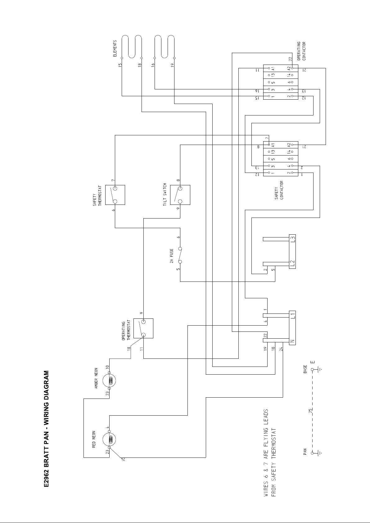
E2962 BRATT PAN - WIRING DIAGRAM
Page 7
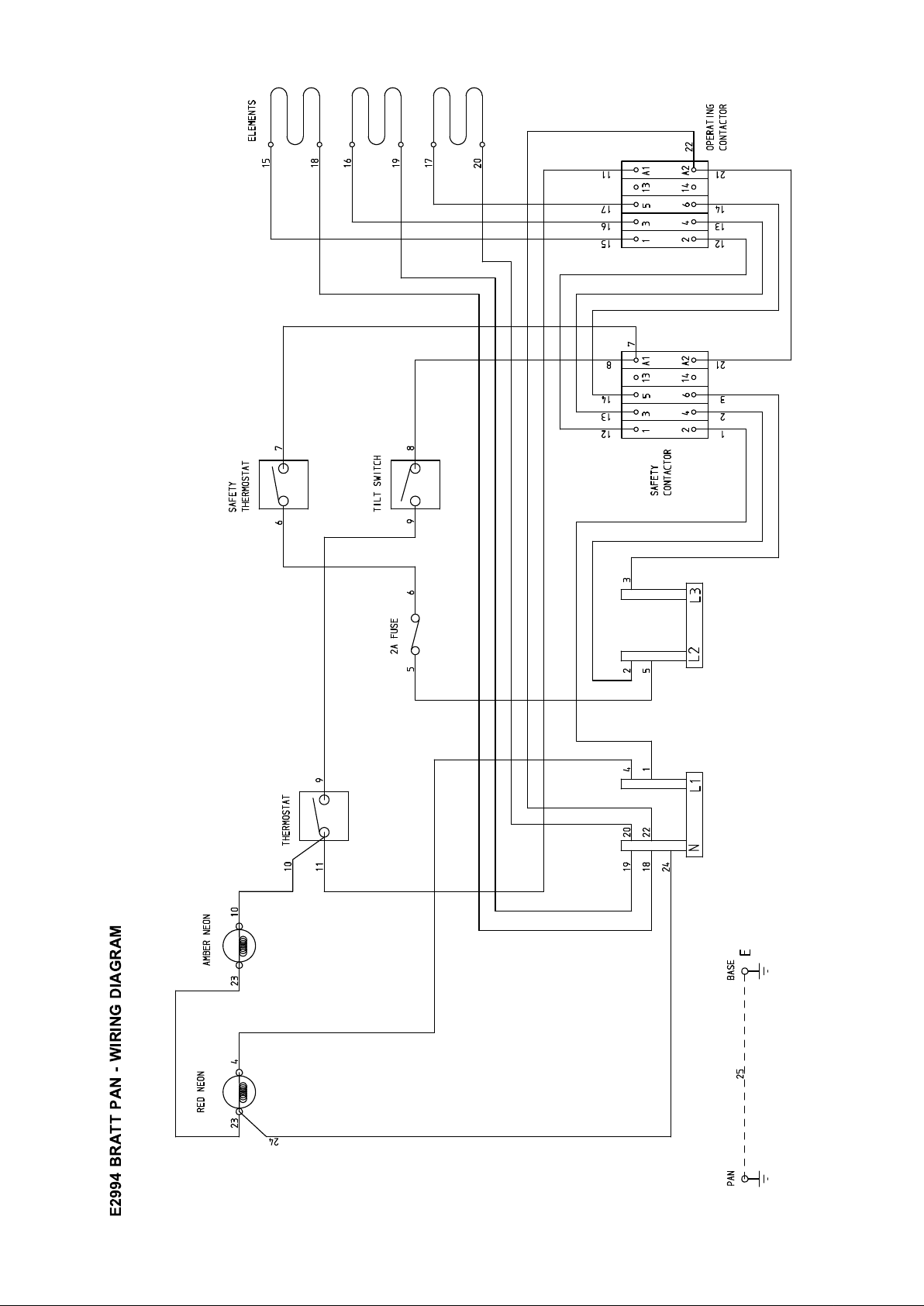
E2994 BRATT PAN - WIRING DIAGRAM
Page 8
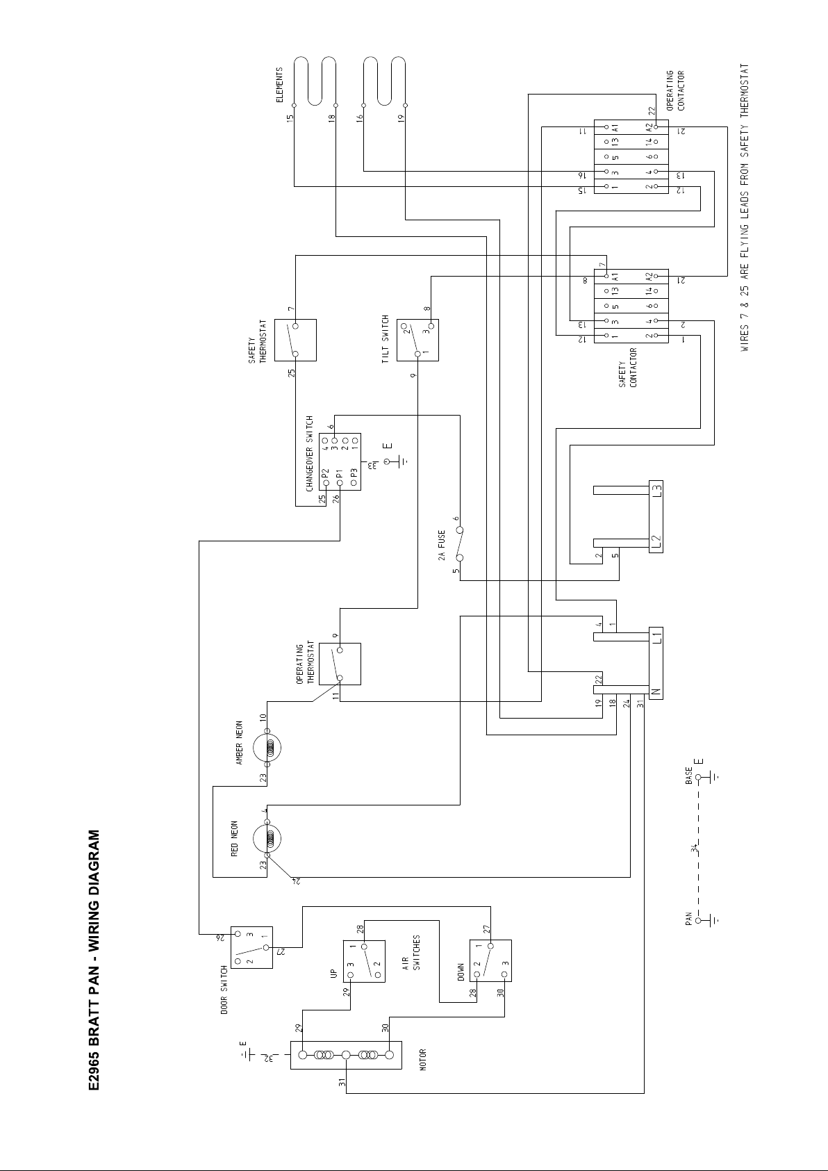
E2965 BRATT PAN - WIRING DIAGRAM
Page 9
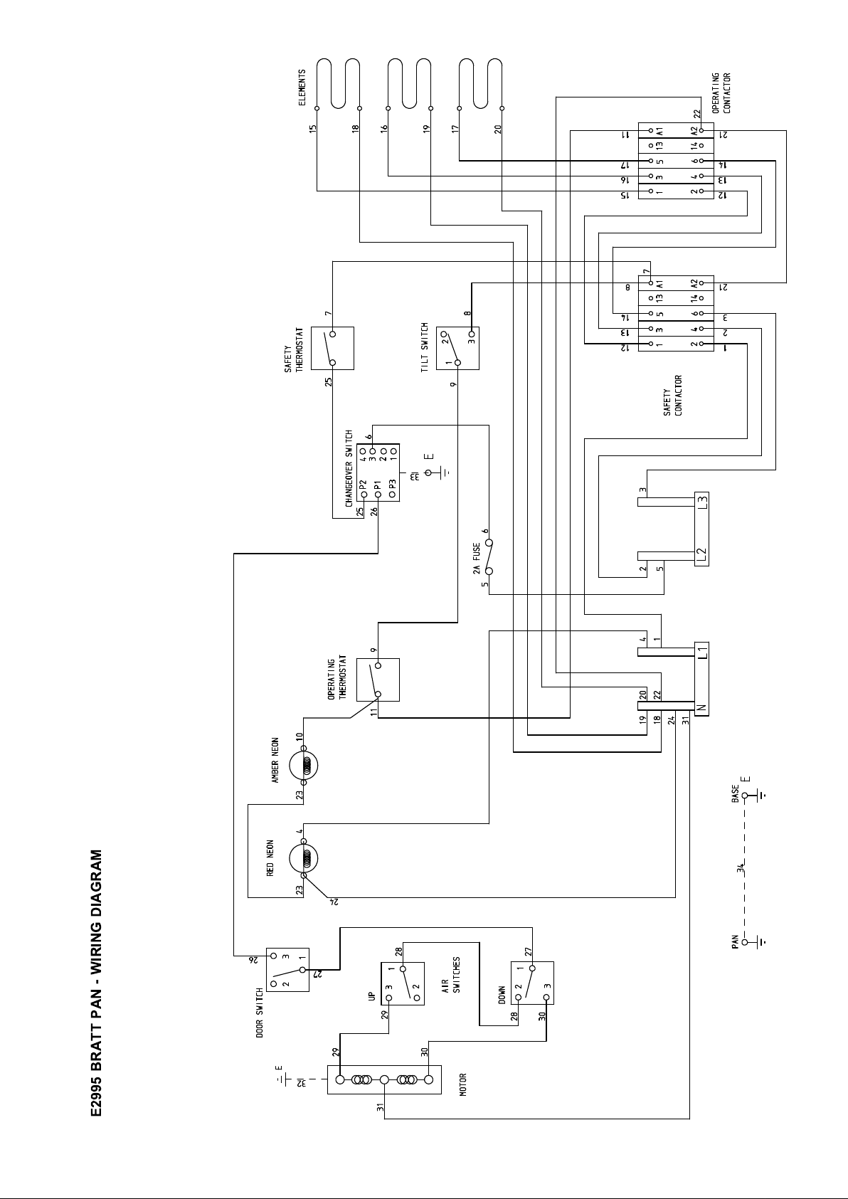
E2995 BRATT PAN - WIRING DIAGRAM
 Loading...