

Page 1

DOMINATOR
PLUS
E3625 & E3925,
ELECTRIC
CHARGRILL
INSTALLATION AND
SERVICING INSTRUCTIONS
CAUTION - READ THESE INSTRUCTIONS BEFORE INSTALLING, COMMISSIONING OR USING
THIS APPLIANCE!
The installer must ensure that the installation of the appliance is in conformity with these instructions
and National Regulations in force at the time of installation. Particular attention MUST be paid to:
BS7671 IEE Wiring Regulations
Electricity at Work Regulations
Health And Safety At Work Act
Fire Precautions Act
This appliance has been CE-marked on the basis of compliance with the Low Voltage and EMC
Directives for the voltages stated on the data plate.
WARNING: THIS APPLIANCE MUST BE EARTHED.
On completion of the installation, these instructions should be left with the Engineer-in-Charge for
reference during servicing. Further to this, The Users Instructions should be handed over to the User,
having had a demonstration of the operation and cleaning of the appliance.
IT IS MOST IMPORTANT THAT THESE INSTRUCTIONS BE CONSULTED BEFORE INSTALLING
AND COMMISSIONING THIS APPLIANCE. FAILURE TO COMPLY WITH THE SPECIFIED
PROCEDURES MAY RESULT IN DAMAGE OR THE NEED FOR A SERVICE CALL.
Upon receipt of the instruction manual, the installer must notify the responsible person(s) with
regard to correct operation and maintenance of the unit. This equipment is ONLY INTENDED
FOR PROFESSIONAL USE and to be operated by QUALIFIED PERSONS.
It is the responsibility of the Supervisor or equivalent to ensure that any user wears
SUITABLE PROTECTIVE CLOTHING. Attention should also be drawn to the fact that some
parts of the unit will, by necessity, become VERY HOT to the extent that burning could occur
if these are touched accidentally.
PREVENTATIVE MAINTENANCE CONTRACT
In order to obtain maximum performance from this unit we would recommend that a maintenance
contract be arranged with SERVICELINE. Visits may then be made at agreed intervals to carry out
adjustments and repairs. A quotation will be given upon request to the contact numbers below.
WEEE Directive Registration No. WEE/DC0059TT/PRO
At end of unit life, dispose of appliance and any replacement
parts in a safe manner, via a licensed waste handler.
Units are designed to be dismantled easily and recycling of all
material is encouraged whenever practicable.
Falcon Foodservice Equipment
HEAD OFFICE AND WORKS
Wallace View, Hillfoots Road, Stirling. FK9 5PY. Scotland.
SERVICELINE CONTACT
Phone: 01438 363 000 Fax: 01438 369 900
T100982 Ref. 2
Page 2

IMPORTANT INFORMATION
Warranty Policy Shortlist
Warranty does not cover :-
• Correcting faults caused by incorrect installation of a product.
• Where an engineer cannot gain access to a site or a product.
• Repeat commission visits.
• Replacement of any parts where damage has been caused by misuse.
• Engineer waiting time will be chargeable.
• Routine maintenance and cleaning.
• Gas conversions i.e. Natural to Propane gas.
• Descaling of water products and cleaning of water sensors where softeners/ conditioners are not fitted,
or are fitted and not maintained.
• Blocked drains
• Independent steam generation systems.
• Gas, water and electrical supply external to unit.
• Light bulbs
• Re-installing vacuum in kettle jackets.
• Replacement of grill burner ceramics when damage has been clearly caused by misuse.
• Where an engineer finds no fault with a product that has been reported faulty.
• Re-setting or adjustment of thermostats when unit is operating to specification.
• Cleaning and unblocking of fryer filter systems due to customer misuse.
• Lubrication and adjustment of door catches.
• Cleaning and Maintenance:
• Cleaning of burner jets
• Poor combustion caused by lack of cleaning
• Lubrication of moving parts
• Lubrication of gas cocks
• Cleaning/adjustment of pilots
• Correction of gas pressure to appliance.
• Renewing of electric cable ends.
• Replacement of fuses
• Corrosion caused by use of chemical cleaners.
Page 3
SECTION 1 - INSTALLATION
UNLESS OTHERWISE STATED, PARTS
WHICH HAVE BEEN PROTECTED BY THE
MANUFACTURER ARE NOT TO BE
ADJUSTED BY THE INSTALLER.
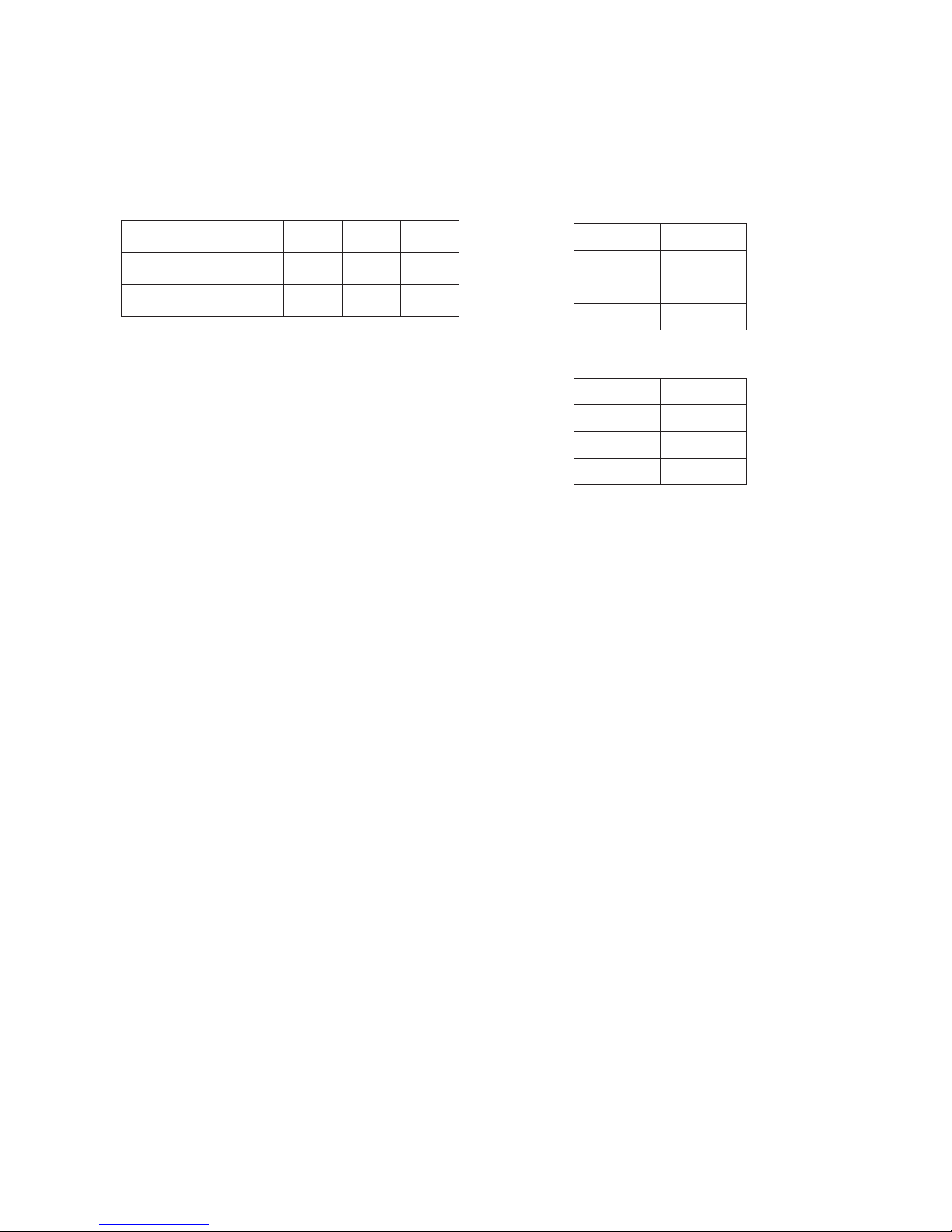
1.1 MODEL NUMBERS, NET WEIGHTS
AND DIMENSIONS
Model
Width
(mm)
Depth
(mm)
Height
(mm)
Weight
(kg)
E3625
600
785
526
56.5
E3925
900
785
526
75.5
1.2 SITING
The appliance should be installed on a level, fireproof
surface, in a well lit and draught free position.
If floor is constructed of combustible material, local fire
requirements should be checked to ensure compliance.
If siting against a wall, it must be of a non combustible
material.
If this is not possible these surfaces should be clad in a
suitable non-combustible, heat-insulating material.
Close attention be paid to fire regulations.
1.3 ELECTRICAL SUPPLY
The units are suitable for AC supplies only. Both
models are for use on three phase supplies.
WARNING - THIS APPLIANCE MUST BE EARTHED
1.4 SUPPLY CONNECTION
A suitable mains input cable should be fitted that
conforms to code designation 60245 IEC 57, cable
type H07RN-F.
A suitably rated isolating switch with contact separation of
at least 3mm in all poles must be installed and wiring
executed in accordance with relevant regulations. We
recommend supplementary electrical protection with the
use of a residual current device (RCD).
Access to mains terminal block is gained by
removing control panel.
1.5 ELECTRICAL RATINGS
Electrical loading is as stated in table below and also
on appliance data plate.
The location of mains isolating switch should be
identified for use in any event of an emergency or during
cleaning.
1.5.1 E3625
Connection
Amps (A)
L1
11
L2
15
L3
11
1.5.2 E3925
Connection
Amps (A)
L1
15
L2
22
L3
22
Connection
Amps (A)
L1
15
L2
22
L3
22
SECTION 2 - ASSEMBLY AND
COMMISSIONING
Note
The following information should be read as applicable to
the unit being assembled.
2.1 ASSEMBLY
a) Position unit. Level it using foot adjusters. To mount
unit upon a purpose built stand, refer to details
supplied with stand.
b) Unit is supplied with terminals for connection to a
suitable mains supply. All wiring must be in accordance
with local regulations.
c) To gain access to terminals, remove control panel and
proceed as follows:
d) Undo and remove upper fixings.
e) Undo fixings below control panel. Remove panel
carefully and set aside.
f) Terminals are now accessible and supply cables can
be fed through rear of unit.
g) After connecting mains supply, replace control panel.
Page 4

2.2 CONNECTION TO AN ELECTRICAL SUPPLY
Connect as detailed in Sections 1.3 and 1.4.
2.3 STARTING UP
Switch on mains supply, red neon will light.
Turn control knob(s) to desired setting.
2.4 INSTRUCTION TO USER
After installation and commissioning is completed, please
hand User Instructions to user.
Ensure that person(s) responsible understand correct
operation and cleaning of appliance.
SECTION 3 - SERVICING AND
MAINTENANCE
BEFORE ATTEMPTING ANY MAINTENANCE,
ISOLATE APPLIANCE AT MAIN SWITCH AND
TAKE STEPS TO ENSURE THAT IT IS NOT
INADVERTENTLY SWITCHED ON.
3.1 CONTROL PANEL - To Remove
a) To gain access to terminals, remove control panel
and proceed as follows:
b) Undo and remove upper fixings.
c) Undo fixings below control panel. Remove panel
carefully and set aside.
3.2 ELEMENT – To Replace
a) Remove control panel as above
b) Remove element wires from contactor(s).
c) Remove unit rear panels.
d) Remove all fixings from underside of hob.
e) Remove element head end covers.
f) Lift off element assembly complete.
g) To refit, follow above instructions in reverse.
3.3 ENERGY REGULATOR
a) Remove control panel as above.
b) Remove control knob from spindle.
c) Remove all electrical connections on regulator and
switch.
d) Remove 2 X screw fixings on front of control panel.
e) Pull switch free of regulator.
3.4 ELEMENT ASSEMBLY MICRO SWITCH
a) Remove rear access panels.
b) Remove element pivot cover, access to fixings
through rear access panels.
c) Disconnect wiring taking note of connections.
d) Remove fixing screws for micro switch taking care not
to damage insulation card
e) To refit, follow above instructions in reverse.
3.5 FUSE
a) Remove control panel.
b) If fuse requires replacing, ensure it is replaced with a
2A fuse.
c) To refit, follow above instructions in reverse.
3.6 INDICATOR LAMP
a) Remove control panel.
b) Remove lamp connections.
c) Remove nut at rear of lamp.
SECTION 4 - SPARES AND
ACCESSORIES
When ordering spare parts, always quote appliance type
and serial number.
This information will be found on data plate.
Short list of spares
Element
Energy regulator
Indicator lamp
Control knob
Contactor
Page 5

E3925 WIRING DIAGRAM 400V 3N~
Page 6

E3925 CIRCUIT DIAGRAM 400V 3N~
R6319
L1 L2 N N E
E
9
10
2 3
11
12
11 9 8
4
5 7
2 6 5
1
6 7
RED
NEON AMBER N EON
AMBER NEON
Page 7

E3625 WIRING DIAGRAM 400V 3N~
Page 8

E3625 CIRCUIT DIAGRAM 400V 3N~
 Loading...