

Page 1

®
Falcon
625 Vehicle-Mount Terminal
User’s Guide
Page 2

Page 3

FALCON
625 Vehicle Mount Terminal
USER’S GUIDE
Page 4

Falcon 625 Vehicle-Mount Terminal
User’s Guide
All rights reserved. No part of this work may be reproduced, transmitted, or stored in
any form or by any means without prior written consent, except by a reviewer, who
may quote brief passages in a review, or as provided for in the Copyright Act of 1976.
Falcon® is a registered trademark of PSC, Inc.
Datalight
trademark of Datalight, Inc.
PhoenixCARD Manager Plus ©1993, 1994 Phoenix Technologies Ltd.
The information in this book was provided by LXE® Inc., an EMS Technologies
Company. Copyright of the original material is owned by LXE Inc.
Microsoft Windows®, Windows® NT, Windows® ME, Windows® 95, Windows® 98,
and Windows® 2000 are registered trademarks of Microsoft Corporation.
Many of the designations used by manufacturers and sellers to distinguish their
products are claimed as trademarks. Where these designations appear here and the
authors were aware of a trademark claim, the designations have been printed with a
trademark (™) symbol.
The information contained in this document is subject to change without notice.
®
is a registered trademark of Datalight, Inc., and ROM-DOS™ is a
Page 5

CONTENTS
About this Guide ....................................................................................v
Style Conventions............................................................................ vi
Document Conventions ........................................................... vi
Keys and Keystroke Conventions ............................................. vi
Radio Frequency Interference......................................................... vii
Warnings................................................................................ viii
Approvals ............................................................................... viii
Technical Support ........................................................................... ix
Chapter 1: About the Falcon 625.......................................................................... 1
Overview .......................................................................................... 2
Quick Start.......................................................................................3
External Connectors .........................................................................4
Keyboards......................................................................................... 5
Keyboard LEDs......................................................................... 6
Control Keys ............................................................................. 7
Power Supply ................................................................................... 8
Battery..............................................................................................9
Chapter 2: Installing the Falcon 625 .................................................................11
Components................................................................................... 12
User’s Guide iii
Page 6

Contents
Back Mounting Bracket...........................................................12
Bottom Mounting Bracket ......................................................12
Torque Measurements ....................................................................15
Installation Procedure .....................................................................16
Connect Cable Ties .................................................................16
Attach Bottom Mounting Bracket to Vehicle...........................18
Attach Falcon 625 to Back Mounting Bracket .........................20
Attach Falcon 625 to Bottom Mounting Bracket.....................20
Connect Antenna ....................................................................22
Connect Serial Bar Code Scanner ............................................23
Connect Serial Printer or PC ...................................................25
Connect Power Cable..............................................................26
Fuse Replacement ...........................................................................31
Chapter 3: Using the Falcon 625.........................................................................33
Turning the Falcon 625 On and Off ..............................................34
Rebooting the Falcon 625...............................................................35
Configuring the Falcon 625............................................................35
Default Settings .......................................................................35
CMOS Setup...........................................................................36
BCWEDGE Setup .................................................................37
The Keyboard.................................................................................38
Secondary Keys (2nd) LED .....................................................38
Hidden Keys............................................................................39
Numeric Keys..........................................................................41
The Display ....................................................................................41
Adjusting the Brightness..........................................................41
Adjusting the Contrast ............................................................42
Panning the Display ................................................................42
Cleaning the Display ...............................................................44
Adjusting the Speaker Volume........................................................44
Suspend Mode................................................................................45
Video Timeout Mode .....................................................................46
iv Falcon 625
Page 7

Preface:
About this Guide
PREFACE CONTENTS
Style Conventions...................................................... vi
Document Conventions ......................................... vi
Keys and Keystroke Conventions............................ vi
Radio Frequency Interference................................... vii
Warnings.............................................................. viii
Approvals ............................................................. viii
Technical Support ..................................................... ix
Page 8
About this Guide
Style Conventions
Document Conventions
Formatting conventions are used throughout this guide as a method of
providing consistency for notes, cautions, and warnings.
Notes Notes appear throughout the manual to provide additional information
on a topic, including technical details, exceptions to instructions and
other pertinent information. These notes are identified by the notepad
symbol to the right and bold italics text.
Cautions Cautions indicate recommendations or important information for the
user to know before proceeding. They can also indicate where certain
actions could cause damage to the unit. They are identified by the
exclamation mark in a triangle and bold italics text. This text appears in
gold bold italics text if the user is viewing the manual in electronic PDF
form on their computer.
War nings Wa rn in gs indicate a danger of injury to the user. They are identified by
the exclamation mark in a triangle and bold italics text. This text
appears in red bold italics text if the user is viewing the manual in
electronic PDF form on their computer.
Keys and Keystroke Conventions
Portable keys and keystroke conventions are used throughout this
manual to identify the difference between a key on the portable and
keystrokes input by the user. Brackets such as: “
on the Falcon Portable. Data or keystrokes entered by the user are
printed in a monospaced typeface.
vi Falcon 625
<Scan>” indicate a key
Page 9

Radio Frequency Interference
This device complies with Part 15 of the FCC Rules. Operation is
subject to the following two conditions:
1. This device may not cause harmful interference, and
2. This device must accept any interference received, including
interference that may cause undesired operation.
This Class A digital apparatus complies with Canadian ICES-003.
Cet appareil numérique de la Classe A est confirme à la norme
NMB-003 du Canada.
This equipment has been tested and found to comply with the limits for
a Class A digital device, pursuant to Part 15 of the FCC Rules. These
limits are designed to provide reasonable protection against harmful
interference in a residential installation. This equipment generates, uses
and can radiate radio frequency energy and, if not installed and used in
accordance with these instructions, may cause harmful interference to
radio communications. However, there is no guarantee that interference
will not occur in a particular installation. If this equipment does cause
interference to radio or television reception, which can be determined by
turning the equipment off and on, the user is encouraged to try to
correct the interference by one or more of the following measures:
z Reorient or relocate the receiving antenna.
z Increase the separation between the equipment and receiver.
z Connect the equipment into an outlet on a circuit different from
which the receiver is connected.
z Consult the dealer or an experienced radio/TV technician for
help.
Radio Frequency Interference
User’s Guide vii
Page 10

About this Guide
Warnings
Changes or modifications to this device not expressly approved by PSC
could void the user’s authority to operate this equipment.
Shielded cables must be used with this unit to ensure compliance with
the FCC Class B limits.
The long-term characteristics or the possible physiological effects of
radio frequency electromagnetic fields have not been investigated by UL.
This product contains a 4.8V nominal NiCd battery. Because there is a
danger of explosion if the battery is incorrectly replaced, it should be
replaced only by an approved field service center.
The Falcon 625 vehicle-mount terminal is designed specifically for use
with 2.4GHz Type II PCMCIA radios. Substitution of other PCMCIA
radios will void the FCC, Industry Canada, and other international
radio certifications for the Falcon 625 and is strictly prohibited.
Substitution of antennas is not permitted unless authorized by PSC. Use
of unauthorized antennas will void the FCC emissions certification of
the Falcon 625.
Approvals
EMI / EMC Standards: Transceiver:
FCC Part 15 Subpart B FCC Part 15, Subpart C
EN 55022: 1994 ETSI 300 328
EN 50082-1: 1997 IC-RSS 210
EN 61000-4-2: 1997 Safety Standards:
EN 61000-4-3: 1997 EN 60950-1: 1992 + Amendments A1..A4
EN 61000-4-4: 1997 UL 1950
EN 61000-4-5 CSA C22.2 No. 950
EN 61000-4-6
EN 61000-4-8
viii Falcon 625
Page 11

Technical Support
PSC Website Support
The PSC website (www.psc.com) is the complete source for technical support and information for PSC products. The site offers the
PSC TekForum, product support, product registration, warranty
information, product manuals, product tech notes, software
updates, demos, and instructions for returning products for repair.
PSC Website TekForum
Search for information on the TekForum by clicking on the Support link on the PSC home page. Browse the TekForum to find
answers to your questions about common technical issues. Register with TekForum to submit a question to the PSC Technical
Support Staff.
Reseller Technical Support
Technical Support
An excellent source for technical assistance and information is an
authorized PSC reseller. A reseller is acquainted with specific types
of businesses, application software, and computer systems and can
provide individualized assistance.
Telephone Technical Support
If you do not have internet or email access, you may contact PSC
technical support at (541) 349-8281.
User’s Guide ix
Page 12

Page 13

1
About the Falcon 625
The Falcon 625 is a tablet-style DOS computer. Rugged and portable, it is designed to be
mounted in a vehicle. The Falcon 625 uses a spread-spectrum 2.4GHz PCMCIA radio for
wireless data communications from a fork-lift truck or any properly configured vehicle. It is
designed to run applications such as PowerNet TN.
This chapter provides an overview of the physical features of the Falcon 625.
CHAPTER CONTENTS
Overview .....................................................................2
Quick Start..................................................................3
External Connectors....................................................4
Keyboards ...................................................................5
Keyboard LEDs....................................................... 6
Control Keys........................................................... 7
Power Supply ..............................................................8
Battery ........................................................................9
Page 14
About the Falcon 625
T
M
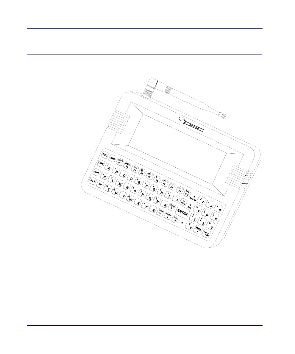
Overview
Figure 1-1: The Falcon 625 Vehicle-Mount Terminal
2 Falcon 625
S
T
A
T
U
S
The Falcon 625 has the following features:
z An Intel 486SX processor running at 25MHz.
z Eight megabytes of flash memory.
z Four megabytes of dynamic RAM (DRAM).
z One Type II/III PCMCIA interfaces.
z Two RS-232 serial connectors.
Page 15

Quick Start
Quick Start
z An easy-to-read 640×200–pixel electroluminescent display with
backlight.
z A built-in keyboard, either QWERTY or ABCD.
z Panning capability.
z A low-temperature option.
z Tough construction for rough, all-weather environments;
environmentally sealed to IP66.
z A spread-spectrum radio contained on a Type II 2.4GHz
PCMCIA card.
This section’s instructions are based on the assumption that a new
system is already configured and requires only installation of accessories
(e.g., an antenna or an external bar code scanner) and a power source.
This user’s guide covers installation and operation of the Falcon 625:
1. Install the mounting bracket on a vehicle.
2. Secure the Falcon 625 in the mounting bracket assembly.
3. Connect the vehicle’s power source to the Falcon 625 power cable.
4. Connect the power cable to the Falcon 625.
5. Attach accessories (e.g., scanner and antenna) to the Falcon 625.
6. Turn the Falcon 625 on.
User’s Guide 3
Page 16
About the Falcon 625
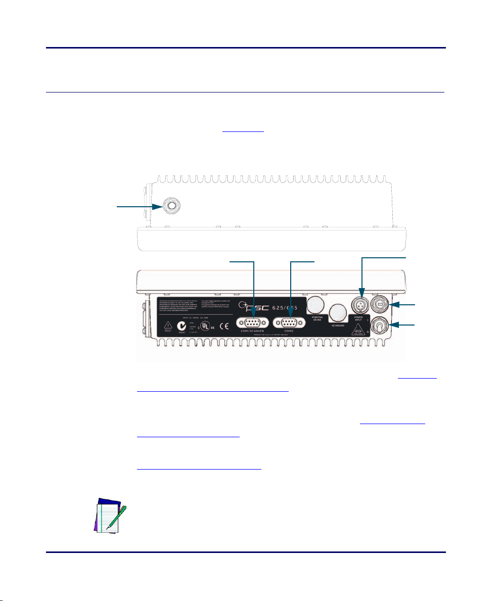
External Connectors
Most external connectors for the Falcon 625 are located on the bottom
of the unit (refer to
Figure 1-2: The Falcon 625 External Connectors
Antenna
Figure 1-2).
COM2COM1
Powe r
connector
Fuse
Powe r
switch
COM1 connects to a serial bar code scanner cable. (Refer to “Connect
Serial Bar Code Scanner” on page 23 for information on connecting a
scanner.)
COM2 connects to a serial printer or PC. (Refer to
Printer or PC” on page 25 for information on connecting a printer or PC.)
“Connect Serial
The antenna connector is located on the top of the unit. (Refer to
“Connect Antenna” on page 22 for information on connecting the
antenna.)
Note: The pointing-device and keyboard ports are not supported.
4 Falcon 625
Page 17
Keyboards
Keyboards
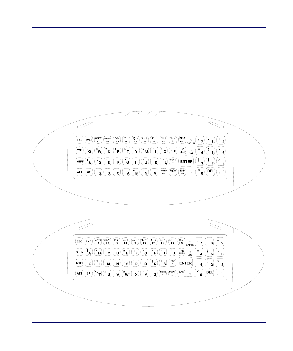
Figure 1-3: The QWERTY Keyboard
Two keyboards are available for the Falcon 625: a QWERTY-style
keyboard and an ABCD-style keyboard (refer to
Figure 1-4). Each
keyboard features a 60-key keypad with individual backlighting for each
key. Each keyboard has all the functions of a full 101-key keyboard,
including a numeric keyboard pad.
STATUS
Figure 1-4: The ABCD Keyboard
STATUS
User’s Guide 5
Page 18
About the Falcon 625
Keyboard LEDs
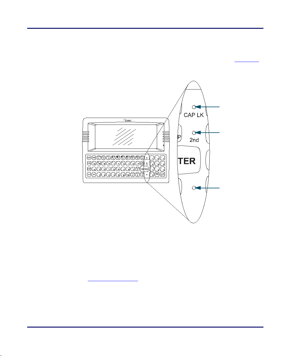
The Falcon 625 keyboard has three LED indicators (refer to Figure 1-5).
Figure 1-5: Keyboard LEDs
Caps Lock mode
LED indicator
TM
Secondary mode
LED indicator
STATUS
Status LED
STATUS
indicator
Caps Lock LED This LED indicates the state of the keyboard Caps Lock mode. If Caps
Lock is enabled, this LED is lit green. When Caps Lock is off, the LED
is dark.
Caps Lock mode on and off, press the 2ND key and then the
Secondary
Mode
To t o g g l e
F1 key. Or, set Caps Lock mode using the CMOS Setup program (refer
Table 3-1 on page 36).
to
The Falcon 625 keyboard is equipped with several secondary keys,
identified by the superscripted text found on the keys.
(2nd) LED
6 Falcon 625
Page 19

Keyboards
When the 2nd state is enabled by a press of the
3-3 on page 39), the yellow 2nd LED is lit, and the 2nd state remains
2ND key (refer to Figure
enabled until another key has been pressed.
Note: Refer to “Secondary Keys (2nd) LED” on page 38 for information
on using the secondary keys.
Status LED The Status LED is lit green when the unit is powered on and the display
is off.
The
Status LED is dark when power is disconnected (or the power is on
and the display is on).
Toggle suspend mode on and off by pressing the
2ND key and F3.
Note: Refer to “Suspend Mode” on page 45 for more information on
using the suspend mode.
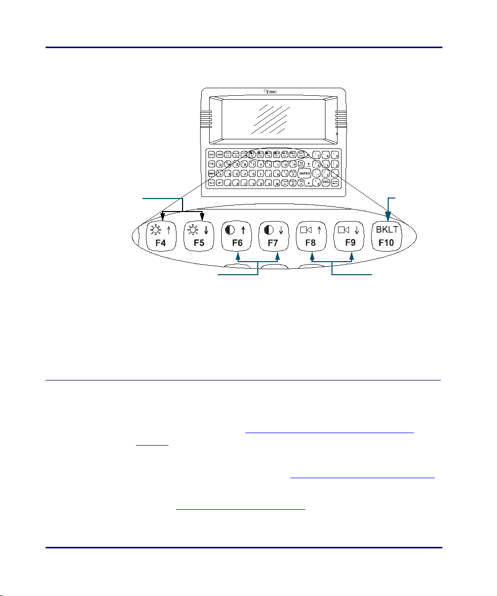
Control Keys
The Falcon 625 has several control keys (refer to Figure 1-6 on page 8).
One key controls the keyboard backlight, two keys control the speaker
volume, two keys control the display contrast, and two keys control the
display brightness.
Note: Refer to “The Display” beginning on page 41 for information on
using the control keys.
User’s Guide 7
Page 20
About the Falcon 625
Figure 1-6: The Control Keys
TM
Display-brightness
control keys
Display-contrast
Power Supply
Vehicle power input for the Falcon 625 is 12V to 80V DC and is
accepted without the need to perform any manual adjustments within
the Falcon 625. (Refer to
page 27.)
If 12V to 80V DC power is not available, an optional universal AC
power supply can be used. (Refer to
control keys
Backlight
control key
Speaker-volume
control keys
“Vehicle 12-80VDC Direct Connection” on
“External Power Supply” on page 26,)
Power input is fused for protection, and the fuse is externally accessible.
(Refer to
8 Falcon 625
“Fuse Replacement” on page 31.)
Page 21

Battery
Battery
The Falcon 625 has an internal 50mAh Nickel Cadmium (NiCd)
backup battery installed to provide power to the unit for a short amount
of time when the primary power has been depleted, removed or has
failed. The backup battery also maintains time, date, and CMOS setup
information when power is off.
Caution: This battery is not user-serviceable. It should be changed
only by authorized service personnel.
User’s Guide 9
Page 22

Page 23

2
Installing the Falcon 625
This chapter describes how to mount the Falcon 625 on a vehicle and provide power to it.
Note: Bolts, washers, and tools required for installation are not
supplied by PSC.
CHAPTER CONTENTS
Components..............................................................12
Back Mounting Bracket......................................... 12
Bottom Mounting Bracket.................................... 12
Torque Measurements ...............................................15
Installation Procedure...............................................16
Connect Cable Ties............................................... 16
Attach Bottom Mounting Bracket to Vehicle......... 18
Attach Falcon 625 to Back Mounting Bracket....... 20
Attach Falcon 625 to Bottom Mounting Bracket... 20
Connect Antenna.................................................. 22
Connect Serial Bar Code Scanner.......................... 23
Connect Serial Printer or PC................................. 25
Connect Power Cable............................................ 26
Fuse Replacement......................................................31
Page 24

Installing the Falcon 625
Components
Back Mounting Bracket
The back mounting bracket (refer to Figure 2-7) attaches to the Falcon
625.
Figure 2-7: The Back Mounting Bracket
z One back mounting bracket
z Six 8-32×7/16 pan head screws (connect to the back of the Falcon
625)
z Six 8-32×3/8 flat screw (connect to the side of the Falcon 625)
Bottom Mounting Bracket
The bottom mounting bracket (refer to Figure 2-8 on page 13) is
mounted to the vehicle and is connected to the back mounting bracket
and Falcon 625 assembly.
12 Falcon 625
Page 25

Components
Figure 2-8: The Bottom Mounting Bracket
z One bottom mounting bracket
z Six ¼ flat washers
z Six ¼ lock washers
z Six ¼-20 bolts
Dimensions for the mounting edge of the bottom mounting bracket are
shown in
shown in
Figure 2-9 on page 14. Suggested mounting positions are
Figure 2-10 on page 14. The viewing angle is 45° to both sides
of the bottom mounting bracket.
User’s Guide 13
Page 26

Installing the Falcon 625
Figure 2-9: Bottom Mounting Bracket Dimensions
1.02 in / 25.9 mm
3.00 in / 76.2 mm
0.88 in / 22.3 mm
Note: The bottom mounting bracket is 0.179 in (4.5 mm) thick. Drawing is not to scale.
Figure 2-10: Suggested Mounting Positions
14.14 in / 359.2 mm
12.1 in / 307.3 mm
6.05 in / 153.6 mm
1.25 in / 31.75 mm
14 Falcon 625
Page 27

Torque Measurements
Torque Measurements
A torquing tool capable of torquing to 50 in/lb (5.64±.56 N/m) is
required for this operation. Torque the pan head screws to 16.0±1 in/lb
(1.8±0.11 N/m) when attaching the back mounting bracket to the
Falcon 625. Torque the ¼-20 bolts to 50.0±5 in/lb (5.64±0.56 N/m)
when assembling the bottom mounting bracket to the back mounting
bracket. (Refer to
Figure 2-11: Torque Measurements
Figure 2-11.)
16 ± 1 in/lb (1.80 ± 0.11 N/m)
50 ± 5in/lb (5.64 ± 0.56 N/m)
User’s Guide 15
Page 28

Installing the Falcon 625
Installation Procedure
Connect Cable Ties
1. Turn the Falcon 625 off and place it face down on a stable surface.
2. Position the hole in a cable tie over a screw hole on the back of the
Falcon 625 (refer to
Figure 2-12: Cable Ties and Push Mounts
Figure 2-12).
16 Falcon 625
Page 29

Installation Procedure
Figure 2-13: Cable Ties on the Falcon 625
Powe r cable
tiedown
3. Insert a pan head screw into the screw hole and fasten it securely.
4. Place the power or COM port cable on top of the cable tie, lift up
the pointed end of the tie, and slide it through the narrow
opening at the top of the cable tie, keeping the serrated sides
together.
5. Slide the tail of the tie closed until the cable is snug.
COM port cable
tiedowns
6. Repeat steps 2 through 5 for each cable.
7. Slide the pointed end of a cable tie through the top opening in a
push mount.
8. Snap the push mount through one of the holes indicated in Figure
2-14 on page 18.
9. Place the power or COM port cable over the tie, lift up the
pointed end of the tie, and slide it through the narrow opening at
the top of the cable tie, keeping the serrated sides together.
10 . Slide the tail of the cable tie closed until the cable is snug.
11. Repeat steps 7 through 10 for each cable.
User’s Guide 17
Page 30

Installing the Falcon 625
Figure 2-14: Cable Ties on the Back Mounting Bracket
Attach Bottom Mounting Bracket to Vehicle
1. Position the bracket to allow access to the switches and ports on
the bottom of the Falcon 625.
18 Falcon 625
2. Attach the bottom mounting bracket to the vehicle mounting
surface using six ¼ bolts (not included) or equivalent fasteners
(refer to
Figure 2-15 on page 19).
Page 31

Installation Procedure
Figure 2-15: Connecting the Bottom Bracket to the Vehicle
Note: Refer to Figure 2-9 on page 14 and Figure 2-10 on page 14 for
dimensions of the bottom mounting bracket and suggested
mounting positions. Mount the bracket to the most rigid
surface available on the vehicle.
User’s Guide 19
Page 32

Installing the Falcon 625
Attach Falcon 625 to Back Mounting Bracket
1. Turn the Falcon 625 off, and place it face down on a stable
surface.
2. Position the back mounting bracket on the Falcon 625, matching
the screw holes in the bracket to the screw holes on the back of
the Falcon 625.
3. Insert a pan head screw into each of six holes. Torque the screws
to 16±1 in/lb (1.8±0.11 N/m).
Figure 2-16: The Falcon 625 Attached to the Back Bracket
Attach Falcon 625 to Bottom Mounting Bracket
1. Insert the mounting bolts (washer first, then the lock washer)
through the curved apertures in the bottom mounting bracket
and into the screw holes in the side bracket (refer to
page 21). Hand-tighten each bolt.
20 Falcon 625
Figure 2-17 on
Page 33

Installation Procedure
TM
Caution: Do not torque bolts until all bolts are in place and viewing
angle is adjusted.
Figure 2-17: Connecting the Falcon 625 to the Bottom Mounting Bracket
2. Loosen the hex bolts on both sides to adjust the viewing angle of
the mounted Falcon 625.
3. Torque the hex bolts to 50±5 in/lb (5.64±0.56 N/m).
Note: Test the torque on the bolts frequently during operation and
retighten them if they become loose.
User’s Guide 21
Page 34

Installing the Falcon 625
4. Connect all cables to the Falcon 625.
Figure 2-18: The Falcon 625 in the Vehicle Bracket
t
Connect Antenna
A Falcon 625 equipped with a radio requires an external antenna.
TM
Place the antenna base over the antenna pin (refer to
page 23). Push the base down and twist it clockwise until the antenna is
secure.
22 Falcon 625
Figure 2-19 on
Page 35

Installation Procedure
Figure 2-19: Connecting the Antenna
Adjust the antenna angle to improve RF communications with the
computer network.
Base
Pin
Caution: Use of unauthorized antennas will void the FCC emissions
certification of the Falcon 625.
Connect Serial Bar Code Scanner
Connect a decoding scanner to the Falcon 625 for bar code input. For
the scanner to function properly with the Falcon 625, use a cable
supplied by PSC.
Caution: Use of a shielded cable is required to maintain FCC and
CISPR22 emissions compliance.
User’s Guide 23
Page 36

Installing the Falcon 625
1. Turn the Falcon 625 off before attaching the scanner cable.
2. Seat the connector firmly over the pins on COM port 1 (refer to
Figure 2-20) and turn the thumbscrews in a clockwise direction.
(Do not overtighten the screws.)
Figure 2-20: Connecting the Serial Scanner Cable
3. Turn the Falcon 625 on.
Refer to the documentation received with the bar code scanner for
complete instructions.
Caution: If the scanner does not work, check the setting for COM1
24 Falcon 625
in CMOS Setup (refer to
“CMOS Setup” on page 36) and
BCWEDGE Setup (refer to “BCWEDGE Setup” on page 37).
The COM1 port should be set to 5Volts in the CMOS
setup.
Page 37

Installation Procedure
Figure 2-21: The Falcon 625 with a Bar Code Scanner Attached
TM
Connect Serial Printer or PC
To connect a printer or PC to the Falcon 625, use a cable supplied by
PSC or a standard null modem cable with a nine-pin D-shell female
connector.
1. Turn the Falcon 625 off before attaching the serial cable.
2. Seat the connector firmly over the pins on COM port 2 (refer to
Figure 2-20) and turn the thumbscrews in a clockwise direction.
Caution: Do not overtighten the screws.
User’s Guide 25
Page 38

Installing the Falcon 625
Figure 2-22: Connecting a Serial Cable to COM2
3. Turn the Falcon 625 on.
Refer to the documentation received with the printer or PC for
complete instructions.
Caution: If the printer or PC does not work, check the setting for
COM2 in CMOS Setup (refer to
The port should be set to Ring Indicator.
“CMOS Setup” on page 36).
Connect Power Cable
External
Power Supply
26 Falcon 625
The optional external power supply (refer to Figure 2-23 on page 27) may
be connected to either a 120V, 60Hz supply or, outside North America,
to a 230V, 50Hz supply, using the appropriate detachable cordset. In all
cases, connect to a properly grounded source of supply provided with
maximum 15-amp overcurrent protection (10-amp for 230V circuits).
Page 39

Installation Procedure
Figure 2-23: External Power Connector
Vehicle 12-
80VDC Direct
Connection
AC input cable
DC output cable
1. Turn the Falcon 625 off.
2. Connect the detachable cordset to the external power supply (IEC
320 connector).
3. Plug the cordset into an appropriate grounded electrical supply
receptacle (AC mains).
4. Connect the power plug to the Falcon 625 (refer to “Power Plug”
on page 30).
For proper and safe installation, the input power cable must be
connected to a fused circuit on the vehicle. This fused circuit requires a
5-amp maximum time delay (slow blow) high interrupting rating fuse.
If the supply connection is made directly to the battery, the fuse should
be installed in the positive lead within 5 inches of the battery’s positive
(+) terminal.
Caution: Installation should be performed by trained service
personnel only. There is a risk of ignition or explosion, as
explosive gas mixtures may be vented from the battery.
Work only in a well-ventilated area. Avoid creating arcs
and sparks at battery terminals.
User’s Guide 27
Page 40

Installing the Falcon 625
Figure 2-24: Direct Vehicle Power Connector Cable (fuse not shown)
To vehicle battery
To vehicle-mounted device
1. Turn the Falcon 625 off.
2. While observing the fuse requirements specified above, connect
the power cable as close as possible to the actual battery terminals
of the vehicle. Connect it to an unswitched terminal in the vehicle
fuse panel, after providing proper fusing.
Caution: For uninterrupted power, electrical supply connections
should not be made at any point after the ignition switch
of the vehicle.
3. Route the cable the shortest way possible. The input cable from
the connection to the battery is rated for a maximum temperature
of 221°F (105°C). When routing this cable, protect it from
physical damage and from surfaces that might exceed this
temperature.
Caution: Always route the power cables so that they do not interfere
with safe operation and maintenance of the vehicle. Do
not expose the cables to chemicals or oil that may cause the
wiring insulation to deteriorate. If the vehicle is equipped
with a panel containing silicon controller rectifiers (SCRs),
avoid routing the power cables near the panel.
28 Falcon 625
Page 41

Installation Procedure
4. Use proper electrical and mechanical fastening means for
terminating the cable. Properly sized “crimp”-type electrical
terminals are an accepted method of termination. Select electrical
connectors sized for use with 18AWG (1mm
Figure 2-25: Connecting the Power Cable to the Vehicle
Table 2-1: Wiring Color Codes for DC Input Power Cabling
Vehicle Supply Wire Color
+12 - 80VDC (DC +) Red with White Stripe
Return (DC -) Red with Black Stripe
Vehicle Chassis (GND) Green
2
) conductors.
Caution: Correct electrical polarity is required for safe and proper
installation. Connecting the cable to the Falcon 625 with
the polarity reversed will cause the Falcon 625’s fuse to be
blown. refer to
Table 2-1 for additional wire color-coding
specifics.
5. Provide mechanical support for the cable by securing it to the
vehicle structure at approximately one-foot intervals, taking care
not to overtighten or pinch conductors or penetrate the outer
cable jacket.
6. Connect the power plug to the Falcon 625 (refer to Figure 2-26 on
page 30).
User’s Guide 29
Page 42

Installing the Falcon 625
Power Plug 1. Turn the Falcon 625 off before attaching the power plug.
2. Insert the power plug into the power connector on the bottom of
the Falcon 625 (refer to
Figure 2-26: Connecting the Power Cable to the Falcon 625
Note: Both the plug and the jack are keyed and cannot be connected
incorrectly.
Figure 2-26).
30 Falcon 625
3. Twist the nut of the power plug clockwise until it is tight.
4. Turn the Falcon 625 on.
Page 43

Fuse Replacement
Fuse Replacement
The Falcon 625 uses a 125V, 5A time delay (slow blow), high current
interrupting rating fuse that is externally accessible and user replaceable.
Should the fuse need replacement, replace it with the same size, rating,
and type of fuse, a Bussman type GMC-5 (5x20mm).
1. Turn the Falcon 625 off and disconnect the power cable.
2. While holding the Falcon 625 over a level surface, use a flathead
screwdriver to push the fuse cover in and twist it one quarter turn
counterclockwise (refer to
Figure 2-27: Replacing the Fuse
Figure 2-27).
Fuse
InsertRemove
3. Pull the fuse holder out and remove the fuse.
4. Place a new fuse in the holder, push the holder into the Falcon
625, and twist it clockwise one quarter turn.
5. Reconnect the power cable to the Falcon 625.
User’s Guide 31
Page 44

Page 45

3
Using the Falcon 625
This chapter explains how to turn on, turn off, reboot, and configure the Falcon 625; how to
access all the functions of a 101-key keyboard; how to adjust the contrast and brightness levels
of the display; and how to pan the display. It also tells how to turn the backlight on and off
and how to adjust the speaker volume. Information about suspend and video timeout modes
is also included.
CHAPTER CONTENTS
Turning the Falcon 625 On and Off ......................... 34
Rebooting the Falcon 625.........................................35
Configuring the Falcon 625......................................35
Default Settings .....................................................35
CMOS Setup.........................................................36
BCWEDGE Setup.................................................37
The Keyboard ........................................................... 38
Secondary Keys (2nd) LED....................................38
Hidden Keys..........................................................39
Numeric Keys ........................................................41
The Display ..............................................................41
Adjusting the Brightness ........................................41
Adjusting the Contrast ..........................................42
Panning the Display...............................................42
Cleaning the Display..............................................44
Adjusting the Speaker Volume ..................................44
Suspend Mode ..........................................................45
Video Timeout Mode................................................46
Page 46

Using the Falcon 625
Turning the Falcon 625 On and Off
Caution: Always turn the computer off before connecting or
disconnecting the power source.
Connect the Falcon 625 to vehicle power or to an AC adapter (refer to
“Connect Power Cable” on page 26).
The power (on/off) switch is located on the bottom of the Falcon 625
(refer to
625 (refer to
display is off.
Figure 3-1: The Falcon 625 Power (On/Off) Switch
Figure 3-1). The Status LED, located on the front of the Falcon
Figure 1-5 on page 6), is lit when the power is on and the
When the system is turned off, the contents of RAM are lost. Save any
needed data and close any running programs before turning the system
off.
Caution: Turning off the Falcon 625 during a write-to-disk function
34 Falcon 625
Powe r switch
may result in corruption of the flash drive.
Page 47

Rebooting the Falcon 625
Rebooting the Falcon 625
When the system is rebooted, the contents of RAM are lost. Save any
needed data and close any running programs before rebooting.
To reboot the Falcon 625 without turning the computer off, press
CTRL+ALT+DEL.
Caution: Rebooting the Falcon 625 during a write-to-disk function
may result in corruption of data on the hard drive.
Configuring the Falcon 625
Default Settings
When the Falcon 625 is turned on or rebooted, the following feature
settings are restored from flash memory. Some of the settings can be
configured using CMOS Setup.
User’s Guide 35
Page 48

Using the Falcon 625
Table 3-1: CMOS Setup Settings
CMOS Setup
Feature Default Configurable?
Keypad Backlight Timed Ye s
Keypad Backlight Timer 1 min. Ye s
Display Timer 1 min. Ye s
Suspend Timer 0 min. Ye s
Off Timer 1 min. Ye s
Caps Lock Mode Off Ye s
Num Lock Mode On Ye s
Keypad Repeat Delay .5 sec. Ye s
Keypad Repeat Rate 10 char/sec Ye s
COM1 5 Volts Ye s
COM2 Ring Indicator Ye s
Use CMOS Setup to change the configurable settings listed above, along
with some other settings.
Accessing
To access the CMOS Setup program:
CMOS Setup
When exiting CMOS Setup, the computer will continue the bootup
process with the new settings.
Caution: Only experienced system administrators should set CMOS
Using CMOS
Setup
36 Falcon 625
The CMOS Setup program opens to the Main menu (refer to Figure 3-2
on page 37). To move between the Main, Advanced, and Exit menus, use
the
1. Reboot the Falcon 625.
2. Press the F2 key while the computer is booting up.
Setup options. Entering incorrect values in CMOS Setup
can cause the Falcon 625 to cease operating or to operate
erratically.
LeftArrow and RightArrow keys.
Page 49

Configuring the Falcon 625
Figure 3-2: The CMOS Setup Main Menu
Main Menu
Time: [16:57:28]
Date: [08/22/2001]
Boot: [A:-C:]
SETUP Msg: [Off]
POST Msg: [off]
Summary: [Off]
z Each menu contains a list of parameters.
z The currently highlighted parameter is selected.
z Use the UpArrow and DownArrow keys to move through the list.
z Use the RightArrow and LeftArrow keys to move through menus.
z To change the setting for a parameter or field, select the current
z Press the spacebar or +/ to move through the available settings.
z Values must be entered into the System Time and System Date
z When done changing CMOS settings, go to the Exit menu.
z To save changes and exit, select Save and Exit and press Enter.
z To restore the default settings, select Load Defaults and press
z To exit CMOS Setup without saving changes, select Exit Without
setting.
fields.
Enter.
and press Enter.
Save
BCWEDGE Setup
BCWEDGE is a DOS based utility which comes installed on the
terminal. Its purpose is to redirect scanner input from COM1 or COM2
to the keyboard buffer. The default setup for BCWEDGE is COM1 at
9600 baud with data = 8, parity = NONE, and stop = 1. This works for
most configurations and scanners.
User’s Guide 37
Page 50

Using the Falcon 625
If the scanner is not attached to COM1 or does not communicate at
these default settings, modify the
AUTOEXEC.BAT file to match the attached scanner. Refer to the
scanner’s documentation to determine the communication settings.
BCWEDGE Parameters Command line: BCWEDGE c=# b=baud
s=dps
Default: BCWEDGE c=1 b=9600 s=8N1
The Keyboard
Secondary Keys (2nd) LED
BCWEDGE command in the
The Falcon 625 keyboard is equipped with several secondary keys,
identified by the superscripted text found on the keys. The secondary
keys are accessed by pressing the
pressing the desired superscripted key.
38 Falcon 625
2nd key (refer to Figure 3-3) and then
Page 51

The Keyboard
Figure 3-3: The 2ND Key
TM
z When the 2nd state is enabled by a press of the 2nd key, the yellow
2nd LED will be lit, and the 2nd state will remain enabled until
another key has been pressed.
z To l e a v e t h e 2nd state without pressing a secondary key, press the
2nd key again.
Hidden Keys
Examples:
z Press 2nd and F10 to toggle the keyboard backlight on and off.
z Press 2nd and F1 to turn Caps Lock on and off.
z Press 2ND and F2 to initiate the DOS Break command.
The Falcon 625 keyboard supports all the functions of a 101-key
keyboard. However, because the keyboards have only 60 keys, not all
functions are visible on the keyboard). Therefore the Falcon 625
keyboards support what are called
hidden keys.
On standard keyboards, many keys can be found in the alphanumeric
section as well as on the numeric keypad. However these keys send
User’s Guide 39
Page 52

Using the Falcon 625
Table 3-2: Hidden Key Keystrokes
distinctly different codes when the keys are pressed. The default codes
for the Falcon 625 keyboard correspond to the numeric keypad on
standard keyboards. To duplicate the code sent when an alphanumeric
key is pressed, the hidden keystroke must be used.
Table 3-2 lists the
hidden keys supported by the Falcon 625.
Hidden Key Keystroke
F11 2ND + SHIFT + F1
F12 2ND + SHIFT + F2
Pause 2ND + SHIFT + F3
Scroll Lock 2ND + SHIFT + F4
Right Shift 2ND + SHIFT + F7
Right Alt 2ND + SHIFT + F8
Right Control 2ND + SHIFT + F9
1 (alphanumeric) 2ND + SHIFT + 1
2 (alphanumeric) 2ND + SHIFT + 2
3 (alphanumeric) 2ND + SHIFT + 3
4 (alphanumeric) 2ND + SHIFT + 4
5 (alphanumeric) 2ND + SHIFT + 5
6 (alphanumeric) 2ND + SHIFT + 6
7 (alphanumeric) 2ND + SHIFT + 7
8 (alphanumeric) 2ND + SHIFT + 8
9 (alphanumeric) 2ND + SHIFT + 9
0 (alphanumeric) 2ND + SHIFT + 0
+ (alphanumeric) 2ND + CTRL + 9
– (alphanumeric) 2ND + CTRL + 8
* (alphanumeric) 2ND + CTRL + I
/ (alphanumeric) 2ND + CTRL + 7
ENTER (numeric) 2ND + ENTER
40 Falcon 625
Page 53

The Display
Numeric Keys
The Falcon 625 keyboard does not have a Num Lock indicator key,
however
Note: Although NumLock can be turned on or off via the computer’s
The Display
Note: For locations of the display and backlight control keys, refer
NumLock is always on.
CMOS Setup Program, the Falcon 625 ignores the
Figure 1-6 on page 8.
to
Off setting.
Adjusting the Brightness
To adjust the display brightness, first press the 2ND key to place the
Falcon 625 in Secondary mode. Then use the brightness keys to control
the electroluminescent display in the following ways:
Press and hold this key to increase the brightness of the
display.
Press and hold this key to decrease the brightness of the
display.
User’s Guide 41
Page 54

Using the Falcon 625
Adjusting the Contrast
The Falcon 625 has no contrast adjustments because it is equipped with
an Electroluminescent Display. The contrast adjustment keys have no
function.
Panning the Display
This section describes panning in a DOS window. Pan the Falcon 625
display up and down to view the entire virtual screen.
To move the screen display up, press the
and then press the
2nd key, then press the Ctrl key, and then press the DownArrow key.
the
UpArrow key. To move the screen display down, press
The default screen display begins at line 1 and displays 12 lines (refer to
Figure 3-4).
Figure 3-4: Panning, Upper Display Window
The first pan-down command moves the pointer to line 8 and displays
10 lines (lines 8 through 18; refer to
2nd key, then press the Ctrl key,
Figure 3-5).
42 Falcon 625
Page 55

The Display
Figure 3-5: Panning, Center Display Window
Figure 3-6: Panning, Lower Display Window
The second pan-down command moves the pointer to line 15 and
displays 10 lines (lines 15 through 25; refer to
Figure 3-6).
User’s Guide 43
Page 56

Using the Falcon 625
At this point, pan-up commands move the pointer to line 15, then to
line 8, and then to line 1. A pan-up command at line 1 does not wrap
the display.
Cleaning the Display
When the display becomes soiled or smudged, clean it with a damp soft
cloth. Do not use paper or cleaning fluids, as they may damage the
display surface.
Adjusting the Speaker Volume
Note: For the location of the speaker-volume control keys, refer to
Figure 1-6 on page 8.
To adjust the speaker volume, first press the 2nd key to place the Falcon
625 in
the speaker volume in the following way:
44 Falcon 625
Secondary mode. Then use the speaker-volume keys to control
Press and hold this key to raise the speaker volume.
Press and hold this key to lower the speaker volume.
Page 57

Suspend Mode
Suspend Mode
The Falcon 625 has a Status LED indicator, located on the front of the
unit (refer to
powered on and the display is off.
The
Status LED is lit green when the Falcon 625 is in suspend mode.
Suspend mode is the lowest power-consumption state possible that
retains the system’s status. When the Falcon 625 is in suspend mode, the
display, keyboard backlights and RS-232 ports are turned off. The
beeper is active.
Figure 1-5 on page 6). It is lit green when the unit is
Place the Falcon 625 in suspend mode at any time by pressing the
key and then the
F3 key. The Falcon 625 will remain in suspend mode
2nd
until:
z The 2ND, F3 key sequence is repeated.
z Vehicle power is removed from the Falcon 625.
z The Falcon625 is turned off using the power switch.
When the Falcon 625 is in suspend mode and the 2ND, F3 key sequence
is repeated:
z The display and keyboard backlights and the RS-232 ports are
turned on.
z The Status LED light is turned off.
z The keypress and COM port buffers are emptied.
Turning the Falcon 625 off when it is in suspend mode causes all
unsaved work (e.g., TE forms and bar code reads) to be discarded.
Turning the Falcon 625 back on after a suspend state turns off suspend
mode.
User’s Guide 45
Page 58

Using the Falcon 625
Video Timeout Mode
The video timer is set using the CMOS Setup program (refer to Tab l e 3 -
1 on page 36). When the video timer times out with no keyboard input,
access to video memory, or COM port activity, the screen display turns
off. The
during video timeout state.
Any keyboard input or COM port activity will bring the Falcon 625 out
of video timeout mode, and the video timer will begin the countdown
again. Pressing the
video timeout mode. A
625. The keypress buffer is emptied when the Falcon 625 returns from
video timeout mode. Host messages that update the display also will
wake the system from video timeout mode.
Status LED on the keyboard is lit steadily (i.e., not flashing)
2ND key has no effect when the Falcon 625 is in
Shift, Ctrl, or Alt keypress will wake the Falcon
46 Falcon 625
Page 59

INDEX
2ND key 3-39
2nd state 1-6, 3-38 to 3-39
LED for 1-6
625 see Falcon 625
A
ABCD keyboard 1-5
antenna connector 1-4
antenna, connecting 2-22
B
back mounting bracket 2-12, 2-20
backlight 1-7
bar code scanner, connecting 2-23 to 2-25
battery
backup
1-9
BCWEDGE setup 3-37 to 3-38
bottom mounting bracket 2-12, 2-18, 2-20
brackets, mounting
back
2-12, 2-20
bottom 2-12, 2-18, 2-20
brightness (display) 1-7, 3-41
C
cable ties 2-16
Caps Lock 1-6
cleaning the display screen 3-44
CMOS setup 3-36 to 3-37
color codes, wiring 2-29
COM ports 1-4
configuration, default 3-35
connectors
antenna
1-4
bar code scanner 1-4
PC 1-4
power 1-4
printer 1-4
contrast (display) 1-7, 3-42
control keys 1-7
brightness 3-41
contrast 3-42
location of 1-7
speaker volume 3-44
D
default settings 3-35
User’s Guide 47
Page 60

Index
display
brightness
cleaning 3-44
contrast 1-7, 3-42
panning 3-42 to 3-44
DRAM 1-2
1-7, 3-41
F
Falcon 625
connecting antenna
connecting bar code scanner 2-23 to 2-25
connecting PC 2-25 to 2-26
connecting power 2-26 to 2-30
connecting printer 2-25 to 2-26
default configuration 3-35
features 1-2 to 1-3
installation 2-11 to 2-30
quick start 1-3
rebooting 3-35
FCC information 1-vii
features 1-2 to 1-3
flash memory 1-2
fuse 1-4
replacing 2-31
2-22
K
keyboards 1-5 to 1-8
ABCD 1-5
control keys 1-7
LEDs 1-6 to 1-7
QWERTY 1-5
L
LED
status
1-7
LEDs on keyboards 1-6 to 1-7
M
measurement, torque 2-15
memory 1-2
mounting brackets
back
2-12, 2-20
bottom 2-12, 2-18, 2-20
N
H
hidden keys 3-39
I
installation 2-11 to 2-30
48 Falcon 625
Num Lock 3-41
numeric keys 3-41
O
on/off switch 3-34
Page 61

Index
P
panning the display 3-42 to 3-44
PC, connecting 2-25 to 2-26
ports, serial 1-4
see also connectors
power
connector
supply 1-8
switch 1-4, 3-34
vehicle 1-8
power, connecting 2-26 to 2-30
external 2-26 to 2-27
vehicle 2-27 to 2-30
printer, connecting 2-25 to 2-26
processor 1-2
1-4
Q
quick start 1-3
QWERTY keyboard 1-5
secondary keys 1-6, 3-38
secondary state 1-6, 3-38 to 3-39
serial connectors 1-4
see also connectors
setup, BCWEDGE 3-37 to 3-38
setup, CMOS 3-36 to 3-37
speaker volume 1-7, 3-44
Status LED 1-7
suspend mode 3-45
T
ties, cable 2-16
timeout, video 3-46
torque measurement 2-15
V
vehicle power 1-8, 2-27 to 2-30
video timeout 3-46
volume, speaker 1-7, 3-44
R
RAM 1-2
rebooting 3-35
RS-232 connectors 1-4
see also connectors
S
scanner, connecting 2-23 to 2-25
scrolling the display 3-42 to 3-44
W
wiring color codes 2-29
User’s Guide 49
Page 62

Page 63

DECLARATION OF CONFORMITY
PSC hereby declares that the Equipment specified below has been
tested and found compliant to the following Directives and Standards:
EMC 89/336/EEC
Directives:
Low Voltage 73/23/EEC
R&TTE 1999/5/EC
STANDARDS
Equipment:
Radios:
Equipment Type: Vehicle Mount Data Terminal Equipment
Product: Falcon® Family Models 625 and 665
Brad West
Vice President
Quality and Process Management
PSC, Inc.
959 Terry Street
Eugene, OR 97402
U.S.A.
EN55022-A:1998, EN 55024:1998
EN60950:2000
ETS 300 328:1995/1996, EN 300 826:1997
EN 301.489.1/17:2000, EN 60950:1992+A4
Peter Lomax
Vice President
Europe, Middle East & Africa
PSC Bar Code Ltd.
Axis 3, Rhodes Way
Wat fo rd
Hertfordshire WD24 4TR
Page 64

Asia Pacific
PSC Hong Kong
Hong Kong
Telephone: [852]-2-584-6210
Fax: [852]-2-521-0291
Italy
PSC S.p.A.
Vimercate (MI), Italy
Telephone: [39] (0) 39/62903.1
Fax: [39] (0) 39/6859496
Australia
PSC Asia Pacific Pty Ltd.
North Ryde, Australia
Telephone: [61] 0 (2) 9878 8999
Fax: [61] 0 (2) 9878 8688
France
PSC S.A.R.L.
LES ULIS Cedex, France
Telephone: [33].01.64.86.71.00
Fax: [33].01.64 46.72.44
Germany
PSC GmbH
Darmstadt, Germany
Telephone: 49 (0) 61 51/93 58-0
Fax: 49 (0) 61 51/93 58 58
Japan
PSC Japan K.K.
Shinagawa-ku, Tokyo, Japan
Telephone: 81 (0)3 3491 6761
Fax: 81 (0)3 3491 6656
Latin America
PSC S.A., INC.
Miami, Florida, USA
Telephone: (305) 539-0111
Fax: (305) 539-0206
United Kingdom
PSC Bar Code Ltd.
Watford, England
Telephone: 44 (0) 1923 809500
Fax: 44 (0) 1923 809 505
www.psc.com
PSC Inc.
959 Terry Street
Eugene, OR
Telephone: (541) 683-5700
Fax: (541) 345-7140
© 2005 PSC R44-2230 (Rev. C) 2/05
 Loading...